Owner’s Manual Keep This Manual For Future Reference.
Contents Contents PRECAUTIONS ...................................5 Using the Oscillator .................................. Using the User Defined Keys ................... Using Operation Lock ............................... Initializing .................................................. Welcome .......................................... 7 Troubleshooting ............................ 49 Package Contents ......................................... About the utility software ...........................
• Explanation of Graphical Symbols CAUTION RISK OF ELECTRIC SHOCK DO NOT OPEN CAUTION: TO REDUCE THE RISK OF ELECTRIC SHOCK, DO NOT REMOVE COVER (OR BACK). NO USER-SERVICEABLE PARTS INSIDE. REFER SERVICING TO QUALIFIED SERVICE PERSONNEL. The lightning flash with arrowhead symbol within an equilateral triangle is intended to alert the user to the presence of uninsulated “dangerous voltage” within the product’s enclosure that may be of sufficient magnitude to constitute a risk of electric shock to persons.
FCC INFORMATION (U.S.A.) 1. IMPORTANT NOTICE: DO NOT MODIFY THIS UNIT! This product, when installed as indicated in the instructions contained in this manual, meets FCC requirements. Modifications not expressly approved by Yamaha may void your authority, granted by the FCC, to use the product. 2. IMPORTANT: When connecting this product to accessories and/ or another product use only high quality shielded cables. Cable/s supplied with this product MUST be used. Follow all installation instructions.
PRECAUTIONS PLEASE READ CAREFULLY BEFORE PROCEEDING * Please keep this manual in a safe place for future reference. WARNING Always follow the basic precautions listed below to avoid the possibility of serious injury or even death from electrical shock, short-circuiting, damages, fire or other hazards.
Connections Handling caution • Before connecting the device to other devices, turn off the power for all devices. Before turning the power on or off for all devices, set all volume levels to minimum. Maintenance • Remove the power plug from the AC outlet when cleaning the device. • Do not insert your fingers or hands in any gaps or openings on the device (vents, etc.). • Avoid inserting or dropping foreign objects (paper, plastic, metal, etc.) into any gaps or openings on the device (vents, etc.
Welcome Welcome About the utility software The provided utility software allows you to use the 01V96i connected with your computer. ■ Yamaha Steinberg USB Driver This is driver software for connecting the 01V96i to your computer. Installing it in your computer will allow audio/MIDI communication to occur.
Welcome Firmware updates This product is designed to allow the internal firmware to be updated in order to improve performance, add functionality, or fix problems. Firmware updates are performed with the product connected to a computer, so you must first install the “Yamaha Steinberg USB Driver” in your computer. Firmware updating is performed using update software. You can download the update software from the following website. http://www.yamahaproaudio.
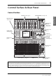
Control Surface & Rear Panel 9 Control Surface & Rear Panel Control Surface AD Input Section (p.
Control Surface & Rear Panel AD Input Section CH1-4 1 2 3 4 5 9 10 11 12 13 15 14 16 1 A A A A A A A A A B B B B B B B B B 2 INPUT (BAL) INSERT 3 4 5 6 7 8 OUT IN (UNBAL) INSERT I/O INSERT I/O INSERT I/O INSERT I/O INSERT I/O INSERT I/O INSERT I/O INSERT I/O INSERT I/O 20dB 20dB 20dB 20dB 20dB 20dB 20dB 20dB 20dB CH15/16 2TR IN PAD -16 -60 -16 -60 -16 -60 -16 -60 -16 -60 -16 -60 -16 -60 -16 -60 -16 -60 GAIN GAIN GAIN GAIN G
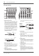
Control Surface Monitor Out & Headphones Section CH5-8 CH9-12 PHANTOM +48V L 1 R IN 2TR -10dBV (UNBAL) PHONES 2 MONITOR 2TR IN 3 4 0 LEVEL 10 MONITOR OUT 0 LEVEL 10 PHONES 1 [SEL] buttons These buttons enable you to select desired channels. The [SEL] button indicator for the currently-selected channel lights up. The channel selected by each [SEL] button depends on the layer selected in the LAYER section (see page 13).
Control Surface & Rear Panel ST IN Section DISPLAY ACCESS Section 1 2 3 4 1 ST IN DISPLAY ACCESS 2 SEL SEL 6 5 3 SOLO SOLO 4 ON ST IN 1 ON SCENE DIO/SETUP PAN/ / INSERT/ ROUTING DELAY DYNAMICS EQ MIDI UTILITY PAIR/ GROUP PATCH EFFECT VIEW 7 8 ST IN 2 9 0 A B 5 1 [SCENE] button 1 [ST IN] button This button selects an ST IN channel pair (ST IN Channels 1 & 2 or 3 & 4) which you can control using the buttons and controls in the ST IN section.
Control Surface 0 [EQ] button Display Section This button displays an EQ page, enabling you to set the equalizer and attenuator of the selected channel. A [EFFECT] button OVER 0 This button displays an Effect page, enabling you to edit the internal effects processors and use optional plug-in cards.
Control Surface & Rear Panel SELECTED CHANNEL Section SCENE MEMORY Section SCENE MEMORY 1 STORE 6 2 Q RECALL 1 HIGH 2 3 3 7 HIGH-MID 4 FREQUENCY LOW-MID 5 8 GAIN LOW 1 [STORE] button This button enables you to store the current mix settings. (See page 42 for more information on Scene Memories.) 2 Scene Up [ ] / Down [ ] buttons 1 [PAN] control This control adjusts the pan of the channel selected by the [SEL] button.
Control Surface Data Entry Section SOLO Section 1 [SOLO] indicator 3 1 This indicator flashes when single or multiple channels are soloed. SOLO CLEAR 1 2 2 [CLEAR] button DEC INC This button “unsolos” all soloed Channels. Control Surface & Rear Panel 4 2 ENTER 1 Parameter wheel This control adjusts the parameter values shown on the display. Turning it clockwise increases the value; turning it counterclockwise decreases the value.
Control Surface & Rear Panel Rear Panel PHANTOM +48V (p. 16) AD Output Section (p. 16) Power Section (p. 18) 2 AD Output Section 1 1 CH1–4 ON/OFF switch 2 CH5–8 ON/OFF switch 3 CH9–12 ON/OFF switch Each of these switches turns on or off the +48V phantom power feed to four corresponding inputs. When the switches are on, +48V phantom power is supplied to the INPUT A connectors. 1 • Make sure that this switch is turned off if phantom power is not required.
Rear Panel 3 STEREO OUT connectors L/R 17 MIDI/USB Section 2 (hot) Female XLR plug 3 (cold) 1 (ground) 1 2 1 MIDI IN/THRU/OUT ports Digital I/O Section These standard MIDI IN, OUT and THRU ports enable you to connect the 01V96i to other MIDI equipment. 2 TO HOST USB port This USB port enables you to connect a computer equipped with a USB 2.0 port.
Control Surface & Rear Panel SLOT Section Follow the steps below to install an optional mini-YGDAI card. 1. Make sure that the power to the 01V96i is turned off. 2. Undo the two fixing screws and remove the slot cover, as shown below. 1 Keep the cover and fixing screws in a safe place for future use. 1 SLOT Optional mini-YGDAI (Yamaha General Digital Audio Interface) I/O cards can be installed in this slot.
Operating Basics 19 5 MIDI indicator Operating Basics This chapter describes basic operations on the 01V96i, including how to use the display and operate the controls on the top panel. This indicator appears when the 01V96i is receiving MIDI data via the MIDI IN port, USB port, or an installed card. 6 Surround mode indicator This indicator identifies the currently-selected Surround mode (ST=stereo, 3-1, 5.1, or 6.1).
Operating Basics Selecting Display Pages Display Interface To select a display page: This section describes how to use the display interface. 1. Press the corresponding button on the top panel to select the desired page group. Rotary Controls & Faders Display pages are grouped by function. To select a page group, press the desired button in the DISPLAY ACCESS section.
Selecting Layers Confirmation Messages For certain functions, the 01V96i prompts you for confirmation before executing the functions, as shown here. Selecting Layers Input Channels and Output Channels (Bus Outs & Aux Outs) are arranged into layers, as illustrated below. There are four layers altogether. Input Channel Layer 17–32 Input Channel Layer 1–16 Move the cursor to YES and press [ENTER] to execute the function, or move the cursor to NO and press [ENTER] to cancel.
Operating Basics Selecting Channels Selecting Fader Modes To select a channel on the 01V96i, press the corresponding [SEL] button. To adjust the Pan and EQ settings, use the rotary controls in the SELECTED CHANNEL section. To select a channel on pages that cover multiple channels, press the corresponding [SEL] button. The function of channel faders (1–16) depends on the selected Layer and Fader mode. 1. Select a layer that includes the desired channel (see page 21). Q 1.
Metering 23 3. Press the FADER MODE [HOME] button Metering This section describes how to check Input and Output Channel levels using the Meter pages. 1. Press the FADER MODE [HOME] button repeatedly until the Meter | Position page appears. repeatedly until the page listed below that contains the desired channels appears. • CH1-32 page This page displays the Input Channel 1–32 levels respectively. This page enables you to set the metering position for Input and Output Channels.
Operating Basics • Effect page This page displays the internal effects processor 1–4 input and output levels altogether. • Stereo page This page displays the Stereo Out output level. If you selected the CH1-32 page or the Master page, use the MASTER MODE parameter to select one of the following three metering signal types: • GATE GR.............The amount of gain reduction for the gate (only for CH1-32) • COMP GR ...........The amount of gain reduction for the compressor • LEVEL ..................
Connections and Setup 25 Connections and Setup This chapter explains how to connect and set up your 01V96i. Connections The following section explains two typical ways to connect the 01V96i to external equipment, although there are numerous others.
Connections and Setup ■ Configuring a recording system that uses a DAW (Digital Audio Workstation) TO HOST USB port Computer Effects processor CH1-4 1 2 3 4 5 6 7 8 9 10 11 CH5-8 12 13 15 14 16 CH9-12 PHANTOM +48V L INPUT connector A A A A A A A A A A A A B B B B B B B B B B B B R IN INPUT OUT 2TR (BAL) -10dBV (UNBAL) PHONES INSERT OUT IN (UNBAL) INSERT I/O INSERT I/O INSERT I/O INSERT I/O INSERT I/O INSERT I/O INSERT I/O INSERT I/O INSERT I
Wordclock Connections and Settings Wordclock Connections and Settings 27 • Star Distribution In this example, a dedicated wordclock distribution box is used to supply wordclock signals from the wordclock master to each wordclock slave individually.
Connections and Setup Specifying the Wordclock Source To digitally connect the 01V96i to external devices, you must specify the wordclock source for the system. Follow the steps below. Note: When you change the wordclock settings on any device in your digital audio system, some devices may output noise due to being out of synchronization. Be sure to turn down your monitoring device before changing wordclock settings. 1.
Input and Output Patching Input and Output Patching The 01V96i is designed to enable you to patch (assign) signals to Inputs and Outputs. This section explains how to view the signals patched to Inputs and Outputs and change the assignment.
• • • • • • • • • • • • Connections and Setup Signals that are currently assigned to the output connectors are shown in the parameter boxes (1) underneath the connector numbers. The parameter indicators are explained below: – ..........................................No assignment BUS1–BUS8 .....................Bus Out 1–8 signals AUX1–AUX8 ...................Aux Out 1–8 Signals ST L/R................................Stereo Out signals INS CH1–INS CH32......
Tutorial Tutorial This chapter describes operations on the 01V96i, organized according to their purpose. 31 3. Press [ENTER] to confirm the change. Note: Alternatively, you can move the cursor to the input channel’s parameter box and then press [ENTER], and make a selection in the “PATCH SELECT” box. In this case, select the desired input connector and channel number, and press [INC] to confirm the change.
Tutorial Setting the Input Levels The explanation here provides an example of adjusting the input level of the signals from instruments or mics connected to INPUT connectors, with the input patching in the default state. 1. While the musicians play the instruments or devices connected to the INPUT connector, adjust each [PAD] and [GAIN] so that [PEAK] flickers briefly when the maximum volume occurs.. Note: The [GAIN] controls adjust the analog input sensitivity.
Pairing Channels 33 Pairing Channels Setting the Routing On the 01V96i, you can pair adjacent odd-even channels for stereo operation. Faders and most mix parameters of paired channels (excluding the Input Patch, phase, routing, and pan parameters) are linked. Pairing Input Channels is useful when you are connecting stereo sources, such as a CD player or synthesizer. To record the 01V96i input signals to an external device, you must specify the destination of the signals for each Input Channel.
Tutorial This section describes how to route signals by combining the above two routing methods. 1. Press the DISPLAY ACCESS [PAN/ROUTING] button repeatedly to display the Pan/Route | Rout1-16 page. This page enables you to select a Bus Out as the signal destination for each channel. 3. To route Input Channel signals via Buses 1–8 to your recorder or DAW, use the 1–8 buttons to specify a Bus Out as the destination for each Input Channel to which an instrument or mic is connected.
EQ’ing the Input Signals 7. Move the cursor to the parameter box for the Input Channels you want to route to Direct Outs, then specify the output connectors or channels. In this example, Input Channel 9–12 signals are routed to ADAT OUT channels 5–8. 35 EQ’ing the Input Signals The 01V96i’s Input Channels feature 4-band full parametric EQ. This section describes how to use the EQ of an Input Channel to adjust the tonal character. 1. Press the LAYER [1–16] button.
Tutorial • F (Frequency) This parameter control specifies the center frequency for cut/boost, with a setting range of 21.2 Hz to 20.0 kHz. • G (Gain) This parameter control specifies the cut/boost amount in the range of –18.0 dB to +18.0 dB. The LOW and HIGH GAIN controls function as filter on/off controls when Q is set to HPF and LPF respectively.
Compressing the Input Signals Compressing the Input Signals The 01V96i’s Input Channels 1–32 feature individual channel compressors. A compressor is an effect used to make the volume level more consistent, or to restrain the maximum level in order to raise the overall volume. Here we describe how to use a compressor to process an input signal. 37 6. Press the [F3] button. The 01V96i displays the Dynamics | Comp Edit page, which enables you to adjust compressor parameters. 1.
Tutorial Using the Internal Effects The 01V96i features four internal multi-effects processors that can be used via Aux Sends and Returns or by inserting them into specific channels. This section describes how to use internal Effects processor 1 via Aux Send 1, and apply reverb to the track signals. 3. Press the DISPLAY ACCESS [EFFECT] button repeatedly until the Effect | FX1 Lib page appears. 1. Press the DISPLAY ACCESS [PATCH] button repeatedly until the Patch | Effect page appears.
Recording to DAW Software via the USB Port 8. Press the FADER MODE [AUX1] button. The button indicator lights up. While the [AUX 1]–[AUX 8] button indicators are lit, faders 1–16 control the Aux 1–8 send levels. In this example, the faders control the send level of the signals routed from Input Channels 1–16 to Aux 1 (Effects processor 1 input). Tip: To reset the fader 1–16 function to normal mode, press the FADER MODE [HOME] button. 9.
Tutorial 3. Make sure that USB1 is assigned to BUS1, and USB2 is assigned to BUS2. If the settings are otherwise, use the Parameter wheel (or [INC]/[DEC]) and [ENTER] to change the settings. 4. Start up your DAW, and set it to use the 2. Move the cursor to the parameter box for the Input Channels you want to route to Direct Outs, then specify the output connectors or channels. Move the cursor to the parameter box, and use the Parameter wheel (or [INC]/[DEC] to specify the patching.
Adjusting the Monitor Levels from the DAW Adjusting the Monitor Levels from the DAW 41 4. Press the DISPLAY ACCESS [PATCH] button repeatedly until the Patch | In Patch page appears. The audio being played back from the DAW can be returned to the 01V96i’s Input Channels and monitored via the MONITOR OUT jacks or PHONES jack. Normally, the signal of the DAW’s stereo bus is sent to an 01V96i Input Channel for monitoring.
Tutorial 9. Press the DISPLAY ACCESS [HOME] button, then press the [F1] button to display the Meter | CH1-32 page. 10. Make sure that [ON] button indicators 1–8 are steadily lit, then raise the [STEREO] fader to 0 dB. Using Scene Memories Scene memories enable you to name and store snapshots of the 01V96i’s mix parameters, internal effect processor settings, remote layers, and input/output patch settings.
Changing the Channel Names 4. Edit the name, move the cursor to the OK Changing the Channel Names button, then press [ENTER]. The new name is now effective. You can change the default name of the input channels (Input Channels 1–32, ST IN Channels 1–4) and output channels (Aux Outs 1–8, Bus Outs 1–8, Stereo Out), if you desire. Changing the Input Channel Names 1. Press the DISPLAY ACCESS [PATCH] button repeatedly until the Patch| In Name page appears.
Tutorial Creating a Custom Layer by Combining Channels (User Assignable Layer) If you set the Remote Layer target to “USER ASSIGNABLE,” you can create a custom layer by combining any 01V96i channels (excluding the Stereo Out). This custom layer is called “User Assignable layer.” 1. Press the DISPLAY ACCESS [DIO/SETUP] button repeatedly until the DIO/Setup| Remote page appears. 2. Set the TARGET parameter to USER ASSIGNABLE, then press [ENTER]. A confirmation window appears. 3.
Using the Oscillator Using the Oscillator The 01V96i features an Oscillator you can use for sound checks. Follow the steps below to use the Oscillator: 1. Press the DISPLAY ACCESS [UTILITY] button repeatedly until the Utility | Oscillator page appears. 1 3 45 4. Move the cursor to the parameter control in the LEVEL section, then rotate the Parameter wheel to set the Oscillator level to minimum. Note: Sinewave and pink noise create unusually high sound pressure.
Tutorial Using the User Defined Keys You can assign any of more than 160 functions to the USER DEFINED KEYS [1]–[8] buttons. If you assign to one of the buttons (or “keys”) a function that is usually executed on the display pages, you can use the assigned button as a shortcut. The Function to User Defined Keys assignments are stored in banks. Each bank accommodates an assignment of all eight buttons. The 01V96i provides eight banks (Banks A–H).
Using Operation Lock Tip: The 01V96i’s settings can be saved on the hard disk of your computer by using Studio Manager software. We strongly recommend that you back up important data. Studio Manager can be downloaded from the following website. http://www.yamahaproaudio.com/ Using Operation Lock The 01V96i features an Operation Lock function that prevents unintentional edits and restricts access to panel operation with a password.
Tutorial 3 PASSWORD This button enables you to change the current password. Move the cursor to the PASSWORD button, then press [ENTER]. The Set Password window appears, enabling you to change the password. Initializing You can delete all currently-recorded settings and restore the factory-preset values, and reset the Operation Lock password to its initial setting. Follow the steps below.
Troubleshooting 49 Troubleshooting ❍ Are the LCD contrast and panel brightness set appropriately? ❍ Is the POWER switch turned on? ❍ If the power still does not turn on, contact a Yamaha service center listed at the end of the manual.
Troubleshooting Signal level is low at a specific frequency ❍ Could the EQ gain be excessively low? ❍ Routing a signal through GEQ or an effect will delay it relative to other signals. If a signal is mixed with the same signal routed differently, a comb filter effect will decrease the level at specific frequencies. Can’t control the 01V96i console from 01V96i Editor ❍ Refer to the 01V96i Editor installation guide on the website.
Error messages 51 Error messages Message Summary Memory backup issues Check Sum Error! Check sum did not match between shutdown and startup. A memory backup problem has occurred, perhaps because the battery is low. Low Battery! The backup battery has run low. Replace the battery. Low Battery ! Replace Battery ! The battery is low. Replace the battery. Low Battery ! Factory Preset ? Replace Battery ! The battery is low. Replace the battery.
Error messages Message Summary DIO issues WRONG WORD CLOCK! The wordclock is incorrect. Cause: The device assigned as the clock source is not running, or a clock source to which the 01V96i cannot synchronize has been selected. Sync Error!(SLOT) Synchronization has not been achieved with the input signal from the MY slot. Check the clock source of the connected device. Sync Error!(2TRD) Synchronization has not been achieved with the 2TR Digital input signal.
Error messages Message 53 Summary Panel operation Not assigned. This message will appear if you operate a user-defined key to which no function has been assigned. This Key doesn’t Work on Current Layer. This message will appear if you operate a key that is non-functional when using a remote layer whose target setting is ProTools, Nuendo, Cubase, or General DAW. Fader calibration data error! Channel xx,yy,… A data error has occurred for channel xx,yy,… fader calibration.
Contents of the Reference Manual Contents of the Reference Manual How to Use This Reference Manual ............................................... 1 Contents of the Owner’s Manual (Booklet) .......... 3 Function Tree .......................................................... 4 Control Surface & Rear Panel ................................. 6 Control Surface .................................................................................. 6 Rear Panel ....................................................
Specifications 55 Specifications General Spec Number of scene memories 99 Internal 44.1 kHz, 48 kHz, 88.2 kHz, 96 kHz USB audio Sampling Frequency Double Rate External The others Signal Delay Normal Rate Normal rate: Double rate: 44.1 kHz ±0.1% 48 kHz ±0.1% 88.2 kHz ±0.1% 96 kHz ±0.1% 44.1 kHz-10% to 48 kHz+6% 88.2 kHz-10% to 96 kHz+6% fs=48 kHz Less than 1.6 ms CH INPUT to STEREO OUT fs=96 kHz Less than 0.
Specifications AD Input (13–16) Gain control 30 dB (–26 to +4), detented Peak indicator LED (red) turns on when post HA level reaches 3 dB below clipping at digital domain Signal indicator LED (green) turns on when post HA level reaches 20 dB below nominal at digital domain AD converter 24-bit linear, 128-times oversampling (fs=44.1, 48 kHz), 64-times oversampling (fs=88.
General Spec 57 Level 0 to –96 dB (1 dB step) On/off — Waveform Sine 100 Hz, sine 1 kHz, sine 10 kHz, pink noise, burst noise Routing BUS1–8, AUX1–8, STEREO L/R STEREO OUT DA converter 24-bit linear, 128-times oversampling (@fs=44.1, 48 kHz), 64-times oversampling (@fs=88.2, 96 kHz) MONITOR OUT DA converter 24-bit linear, 128-times oversampling (@fs=44.1, 48 kHz), 64-times oversampling (@fs=88.
Specifications Comp-type4 Attenuator EQ AUX1–8 Power Requirements Dimensions Pre EQ/pre fader/post fader –96.0 to +12.0 dB (0.1 dB step) 4-band PEQ5 On/off On/off — Fader 100 mm motorized Delay 0–29100 samples Metering INTERNAL EFFECTS (EFFECT 1–4) On/off Displayed on LCD Peak hold on/off Number of effects 4@44.1kHz, 48kHz Bypass On/off In/out 2-in, 2-out Effect-in from AUX1–8/INSERT OUT Effect-out to Input patch U.S.
General Spec 59 EQ Parameters LOW/HPF L-MID 0.1–10.0 (41 points) low shelving HPF Q F H-MID 0.1–10.0 (41 points) HIGH /LPF 0.1–10.0 (41 points) high shelving LPF 21.2 Hz–20.0 kHz (1/12 oct step) ±18 dB (0.1 dB step) HPF: on/off G ±18 dB (0.1 dB step) ±18 dB (0.1 dB step) LPF: on/off Gate Parameters Threshold –54 dB–0 dB (0.1 dB step) Range –70 dB–0 dB (1 dB step) Attack 0 ms–120 ms (1 ms step) 0.02 ms–1.96 s (216 points) @ 48 kHz Gate Hold 0.02 ms–2.13 s (216 points) @ 44.1 kHz 0.
Specifications Comp Parameters Compressor Threshold –54 dB–0 dB (0.1 dB step) Ratio (x :1) x=1, 1.1, 1.3, 1.5, 1.7, 2, 2.5, 3, 3.5, 4, 5, 6, 8, 10, 20, (16 points) Out gain 0 dB to +18 dB (0.1 dB step) Knee Hard, 1, 2, 3, 4, 5 (6 step) Attack 0 ms–120 ms (1 ms step) 5 ms–42.3 s (160 points) @ 48 kHz Release 6 ms–46.0 s (160 points) @ 44.1 kHz 3 ms–21.1 s (160 points) @ 96 kHz 3 ms–23.0 s (160 points) @ 88.2 kHz Expander Threshold –54 dB to 0 dB (0.1 dB step) Ratio (x :1) x=1, 1.
Analog Input Spec 61 Analog Input Spec Input PAD GAIN Actual Load Impedance For Use With Nominal –60 dB 0 INPUT A/B 1–12 3 kΩ –16 dB 50–600 Ω Mics & 600 Ω Lines Input level Sensitivity1 Nominal Max. before clip –70 dBu (0.245 mV) –60 dBu (0.775 mV) –40 dBu (7.75 mV) –26 dBu (38.8 mV) –16 dBu (123 mV) +4 dBu (1.23 V) –6 dBu (388 mV) +4 dBu (1.23 V) +24 dBu (12.28 V) –36 dBu (12.3 mV) –26 dBu (38.8 mV) –6 dBu (388 mV) –6 dBu (388 mV) +4 dBu (1.23 V) +24 dBu (12.
Specifications Digital Input Spec Input 2TR IN DIGITAL ADAT IN Format IEC 60958 ADAT 1 Data length Level Connector 24-bit 0.5 Vpp/75 Ω RCA pin jack 24-bit — OPTICAL 1. ALESIS proprietary multichannel optical digital interface format Digital Output Spec Output 2TR OUT DIGITAL ADAT OUT Format Data length Level Connector IEC 609581 Consumer use 24-bit3 0.5V pp/75 Ω RCA pin jack ADAT2 24-bit3 — OPTICAL 1.
I/O SLOT Spec 63 I/O SLOT Spec The I/O SLOT accepts a mini YGDAI card. The SLOT has a serial interface. Refer to the Yamaha Pro Audio website for the latest information on mini-YGDAI cards. http://www.yamahaproaudio.
Specifications MIDI/USB/WORD CLOCK I/O Spec I/O Port Format Level USB 2.0 — B type USB connector Audio: 16 in/16 out MIDI: 5 ports IN1 MIDI — DIN Connector 5P OUT MIDI — DIN Connector 5P THRU DIN Connector 5P TO HOST USB MIDI WORD CLOCK Connector in Console MIDI — IN — TTL/75 Ω BNC Connector OUT — TTL/75 Ω BNC Connector 1. MIDI IN can use as TIME CODE IN MTC.
Options 65 Options Rack Mounting the 01V96i Using RK1 Rack Mount Kit You can rack mount the 01V96i using an optional RK1 Rack Mount Kit. 1. Hold one of the brackets against one side of the 01V96i so that the bracket ear projects to the side, and align three holes on the bracket with the holes on the side of the 01V96i, as shown in the illustration below. 2. Affix the bracket using three screws included in the RK1 package. 3. Attach the other bracket to the other side of the 01V96i in the same way.
Index Index Symbols /INSERT/DELAY button .............. 12 Display ............................................. 13, 19 DISPLAY ACCESS Section ................. 12 Display Interface ................................... 20 Display Pages ......................................... 20 Driver ........................................................ 7 DYNAMICS button ............................. 12 Numerics E 01V96i Editor ...........................................7 1–16/17–32 buttons ...................
Index Q U Q (slope) .................................................35 Q control .................................................14 USB 2.0 port ...........................................17 USB OUT ................................................30 User Assignable Layer ...........................44 User Define Select window ..................46 User Defined Keys .................................46 USER DEFINED KEYS Section ..........14 UTILITY button ....................................
01V96i Block Diagram
01V96i Level Diagram Analog Analog dBu +24 +20 +10 +4 0 -2 Digital dBFS 0 -10 -20 -30 -10 -40 -20 -50 -30 -60 -40 -70 -50 -80 -60 -90 -70 -100 -80 -110 -90 -120 -100 -130 -110 -140 -120 -150 -130 -160 -140 -170 -150 -180 -160 -190 -170 -200 -180 -210 -190 PAD GAIN INSERT Digital AD INPUT PATCH PHASE Digital GATE INSERT ATT. EQ INSERT COMP DELAY ON LEVEL INSERT PAN BUS Adder INSERT ATT.
ADDRESS LIST NORTH AMERICA CANADA Yamaha Canada Music Ltd. 135 Milner Avenue, Toronto, Ontario, M1S 3R1, Canada Tel: +1-416-298-1311 U.S.A. Yamaha Corporation of America 6600 Orangethorpe Avenue, Buena Park, CA 90620, U.S.A. Tel: +1-714-522-9011 CENTRAL & SOUTH AMERICA MEXICO Yamaha de México, S.A. de C.V. Av. Insurgentes Sur 1647 Piso 9, Col. San José Insurgentes, Delegación Benito Juárez, México, D.F., C.P. 03900, México Tel: +52-55-5804-0600 BRAZIL Yamaha Musical do Brasil Ltda.
Yamaha Pro Audio global website http://www.yamahaproaudio.com/ Yamaha Downloads http://download.yamaha.