STUDIO MANAGER for Owner’s Manual Keep This Manual For Future Reference.
i Important Information Important Information Studio Manager Exclusion of Certain Liability Manufacturer, importer, or dealer shall not be liable for any incidental damages including personal injury or any other damages caused by improper use or operation of Studio Manager. Trademarks Apple and Macintosh are registered trademarks of Apple Computer, Inc. PowerPC is a registered trademark of International Business Machines Corporation. Pentium and Celeron are registered trademarks of Intel Corporation.
ii Contents Contents 1 Getting Started . . . . . . . . . . . . . . . . . . . . . . . . . . . . 1 Introduction . . . . . . . . . . . . . . . . . . . . . . . . . . . . . . . . . . . . . . . . . . . . . . . . . . . . . . . . 1 Contents of the CD-ROM . . . . . . . . . . . . . . . . . . . . . . . . . . . . . . . . . . . . . . . . . . . . . 1 Minimum System Requirements . . . . . . . . . . . . . . . . . . . . . . . . . . . . . . . . . . . . . . . . 2 Software Installation for Windows . . . . . . . . . . . . .
1 Chapter 1—Getting Started 1 Getting Started Introduction The Yamaha Studio Manager for DM2000 allows you to control and display DM2000 parameters on your computer. This Owner’s Manual contains information about installing and operating Studio Manager for DM2000. Please refer to the DM2000 Owner’s Manual for detailed information on operating the DM2000.
Minimum System Requirements 2 Minimum System Requirements For Windows Listed below are the minimum system requirements for a PC to run each item of software supplied on the CD-ROM. Note: Your operating system may have system requirements other than those specified for the software.
3 Chapter 1—Getting Started • • • Display resolution of 1024 x 768 pixels, 256 colors (1280 x 1024 pixels, 32,000 colors recommended) Mac OS 8.6 to 9.2.2 (Mac OS X not supported) OMS 2.3.3 or later Note that in OMS MIDI Setup, “Run in Background” must be turned on. Note: If you are using a PowerBook and it is on battery power, go to “Power conservation settings” and deselect “Allow processor cycling.
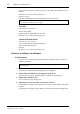
Software Installation for Windows 4 USB MIDI Driver To operate the DM2000 from your computer via USB, you’ll need to install the USB MIDI driver. This software transfers MIDI data back and forth between Studio Manager and the DM2000 via USB. DM2000 Computer Sequence Software USB cable Driver For Windows 98/Me, see the next section. For Windows 2000, see page 6. For Windows XP, see page 7. Installing on a Windows 98/Me system 1 Turn on your PC and start Windows.
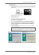
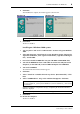
5 Chapter 1—Getting Started 5 Click Next. The window appears as shown below. 6 Select “Search for the best driver for your device. (Recommended).” Click Next. The window appears, as shown below. 7 Select “CD-ROM drive” only, as shown. Click Next. Note: You may be asked to insert your Windows CD-ROM so that the driver can be located. Specify the USBdrv_ folder of the CD-ROM (such as D:\USBdrv_\) and continue the installation.
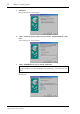
Software Installation for Windows 8 6 Click Next. After installation is complete, the window appears as shown below. Windows 98 Windows Me Note: It may take up to ten seconds for this window to appear. 9 Click Finish. The driver is installed. Installing on a Windows 2000 system 1 Turn on your PC and use the “Administrator” account to log into Windows 2000.
7 Chapter 1—Getting Started Installing on a Windows XP system 1 Turn on your PC. 2 Click Start, Control Panel. If the Control Panel is displayed as shown, click “Switch to classic view” in the upper left of the window. All control panels and icons are displayed. 3 Select System, Hardware, Driver signatures, Driver signature options, select “Ignore—Install software without asking for confirmation,” and click OK.
Software Installation for Macintosh 3 8 Follow the on-screen directions to install the software. A YAMAHA folder is created in C:\Program Files (the default location). The files for Card Filer are created inside that folder. Refer to “Card Filer Manual.pdf” for information on using Card Filer. CBX Driver 1 Double-click the “Mididrv_” folder. The folder opens and various files including “Setup.exe” are displayed. 2 Double-click “Setup.exe.” The YAMAHA CBX Driver setup dialog appears.
9 Chapter 1—Getting Started 4 After the installation, click Restart. Note: After the installation is complete, you may encounter an error message warning that the installer did not close. In this case, choose Quit from the File menu to close the installer. Then restart the computer. After restarting, the Opcode folder is created containing the OMS Applications folder (on the startup disk as the default location). 5 Copy the “OMS_2.3_Mac.
Software Installation for Macintosh 10 6 Click Install. The following message appears: “This installation requires your computer to restart after installing this software. Click Continue to automatically quit all other running applications.” 7 Click Continue. Note: To cancel the installation, click Cancel. The installation starts. If the driver has already been installed, the following message appears. To quit the installation, click Quit.
11 Chapter 1—Getting Started Setting up OMS OMS Studio Setup files for the DM2000 are supplied on the included CD-ROM. The setup files are used for setting up OMS when using the serial or USB ports. Note: When using USB, OMS and the USB MIDI driver should be installed before proceeding. 1 Turn off the DM2000 and use a USB cable to connect the USB port of the computer (or the USB hub) to the TO HOST USB port of the DM2000. 2 Turn on the DM2000 and start the computer.
Connecting to the DM2000 12 The OMS studio setup is complete. Note: After the OMS Studio Setup above has been completed, your computer will recognize only the DM2000 as a MIDI instrument. If you use another MIDI instrument in addition to the DM2000,or you add a second DM2000 to the existing system, you should create an original Studio Setup file. Refer to the on-line manual supplied with OMS for more information.
13 Chapter 1—Getting Started Starting Studio Manager For Windows, click the “Start” button and select Programs, YAMAHA Studio Manager, DM2000, Studio Manager for DM2000. For Mac, open the Studio Manager folder and double-click “YAMAHA Studio Manager for DM2000.” Studio Manager displays its startup screen, shown below, and then takes a few seconds to initialize itself before opening the Console window. Quitting Studio Manager Choose Quit from the File menu.
Using Studio Manager Online & Offline 14 Shown below left is the Mac version of the dialog, and below right is the Windows version. Using Studio Manager Online & Offline When Studio Manager is started, it opens a new Session using its default settings and checks whether an active DM2000 is connected, active meaning connected and turned on.
15 Chapter 2—Console Window 2 Console Window The Console window is Studio Manager’s main window and opens when Studio Manager is started. It provides an overview of the mixer channels, and most major functions can be operated from here. The window is divided into the Channel Section and the Master Section. The Channel Section displays a Layer (24 channels) at a time, and Layers can be selected by using the LAYER buttons in the Master Section.
Input Channels 16 Input Channels An Input Channel from the Console window is shown below. A SOURCE parameter 1 B C D 5 6 7 8 9 J K L M N O P Q This parameter is used to select an Input source. To select an Input source, click the parameter and choose from the list that appears. B Bus Out routing buttons These buttons are used to route the Input Channel’s signal to one or more of the Bus Outs. C STEREO button This button is used to route the Input Channel’s signal to the Stereo Out.
17 Chapter 2—Console Window P Delay Time This parameter is used to set the delay time of the Delay function. Delay times can be set by dragging. Q Channel number Displays the Channel number of the channel. R AUX section These controls are used to set the levels of the 12 Aux Sends. To turn an Aux Send on or off, click its number. To set an Aux Send level, drag the end of the bar next to the Aux Send’s number or click a point along the length of the bar.
Master Section 18 Master Section The Master Section is situated on the right side of the Console window. 1 A ONLINE/OFFLINE status indicator This indicator shows whether Studio Manager is online or offline. See “Using Studio Manager Online & Offline” on page 14 for more information. B Meters (Stereo shown) 2 These meters display the output level of the Stereo Out when the PAN CONTROL is set to “STEREO,” and the Bus Outs when the PAN CONTROL is set to “SURR.
19 Chapter 2—Console Window Master Section Meters If the PAN CONTROL is set to “SURR” (Surround mode), the Meters display the levels of the Bus Outs used for surround processing. Shown on the right are how the Meters appear in 3-1 and 5.1 Surround modes. In 3-1 Surround mode, Bus Outs 1 to 4 levels are labelled as the Left, Center, Right, and Surround channels respectively. In 5.
Master Layer Channels 20 Master Layer Channels When the Master Layer is selected in the Master Section, the Bus Outs, Aux Sends, and Matrix Sends can be selected. A Bus Out is shown below. Aux Sends and Matrix Sends appear the same except that they do not have a STEREO button. A STEREO button (Bus Out only) This button is used to route the Bus Out to the Stereo Out. B INSERT button This button is used to turn on and off the Bus Out’s Insert.
21 Chapter 2—Console Window Remote Layer Channels When a Remote Layer is selected in the Master Section, Remote Channels can be selected. A Channel number Displays the Channel number of the channel. B SELECT button This button is used to select the Remote Channel. C ON button This button turns the Remote Channel on and off. It is colored orange when the channel is turned on. D Short Channel name This is the channel’s Short Channel name, which can be edited. To edit the name, click it and type.
22 Selected Channel Window 3 Selected Channel Window • • • • • • To open the Selected Channel window, choose Selected Channel from the Windows menu. The Selected Channel window is used for displaying and editing a single channel in detail. Its content varies depending on the selected channel’s facilities. There are six variations of the Selected Channel window, they are: Input Channel. See below. Bus Out. See page 24. Aux Send. See page 25. Stereo Out. See page 27. Matrix Send. See page 28.
23 Chapter 3—Selected Channel Window and hold time of the Gate, and the Gate’s curve is drawn on its display graph. The GR meter indicates the level of gain reduction being applied by the Gate. The ON button turns the Gate on and off, and the LINK button is used to pair the Gate of the currently selected Input Channel with its adjacent channel, with the Pair mode setting on the DM2000 determining whether pairing is horizontal or vertical.
Bus Outs 24 I INSERT section This section contains the parameters for the currently selected Input Channel’s Insert. The INSERT button turns the Insert on and off. The OUT and IN parameters are used to select the channel’s Insert Out and Insert In, and the POSITION parameter is used to specify the Insert’s position in the channel’s signal path. J FADER GROUP/MUTE GROUP section This section contains the buttons for assigning the currently selected Input Channel to the Fader Groups and Mute Groups.
25 Chapter 3—Selected Channel Window D Bus Out Routing/Pan/Level section This section contains the controls for the currently selected Bus Out’s routing, pan, and level functions. The TO STEREO button turns on and off the Bus to Stereo routing, and the rotary controls are used to set the Bus to Stereo level and Pan position. The SOLO button is used to solo the Bus Out, the ON button to turn the Bus Out on and off, and the Channel Fader to set the Bus Out level. The AUTO button is not used in Version 1.
Aux Sends 26 the Long Channel name, which can be edited. To edit the name, click it and type. The LIBRARY button is not used in Version 1.0 of Studio Manager for DM2000. B EQUALIZER section This section contains the controls and display graph for the currently selected Aux Send’s 4-band Parametric Equalizer and is identical to the Equalizer section of the Input Channels. See page 23. C DELAY section This section contains the controls for the currently selected Aux Send’s Delay function.
27 Chapter 3—Selected Channel Window Stereo Out The Selected Channel window for the Stereo Out is shown below. Note that this window cannot be opened from the Windows menu if a Remote Layer is selected. 1 5 2 6 3 4 7 A CHANNEL SELECT section Channels can be selected by clicking the Channel ID and choosing from the list that appears, or by clicking the left and right Channel Select buttons. This section also displays the Long Channel name, which can be edited. To edit the name, click it and type.
Matrix Sends 28 Out and Insert In, and the POSITION parameter is used to specify the Insert’s position in the channel’s signal path. G FADER GROUP/MUTE GROUP section This section contains the buttons for assigning the Stereo Out to the Fader Groups and Mute Groups. Matrix Sends The Selected Channel window for the Matrix Sends is shown below. 1 2 3 4 8 5 9 6 7 J A AUX section This section contains the controls for the currently selected Matrix Send’s inputs from the Aux Sends.
29 Chapter 3—Selected Channel Window F DELAY section This section contains the controls for the currently selected Matrix Send’s Delay function. The rotary control is used to set the delay time, and the ON button turns the Delay function on and off. G Matrix Send Level section This section contains the ChannelON button, the SOLO button, and the Channel Fader for the currently selected Matrix Send. The AUTO button is not used in Version 1.0 of Studio Manager for DM2000.
Patch Editor Window 30 4 Patch Editor Window To open the Patch Editor window, choose Patch Editor from the Windows menu. The Patch Editor window’s five pages are used to patch Inputs, Outputs, Inserts, Direct Outs, and Effects. Pages can be selected by clicking the tabs along the top of the window. Input Patch Page 1 2 3 5 4 6 7 8 A Input Patch page tab This tab is used to select the Input Patch page. B Channel IDs This column displays the Channel IDs.
31 Chapter 4—Patch Editor Window G LIBRARY button This button is not used in Version 1.0 of Studio Manager for DM2000. H Patch grid This grid is used to patch input ports to the Input Channels. To patch, click a square in the grid that is aligned with an input port and Input Channel. A blue dot indicates that a connection is made. Output Patch Page 2 3 1 4 5 6 7 A Output Patch page tab This tab is used to select the Output Patch page. B Channel IDs This column displays the Channel IDs.
Insert Patch Page 32 G Patch grid This grid is used to patch the Output signals to the output ports. A red dot indicates that a connection is made. Insert Patch Page 2 3 1 5 4 6 A Insert Patch page tab This tab is used to select the Insert Patch page. B Channel IDs This column displays the Channel IDs. C Long Channel names This column displays the Long Channel names, which can be edited here. To edit a name, click it and type. D LIBRARY buttons These buttons are not used in Version 1.
33 Chapter 4—Patch Editor Window Effect Patch Page 1 2 3 4 A Effects Patch page tab This tab is used to select the Effect Patch page. B Effects Processors #1 and #2 inputs These parameters are used to select sources for the inputs of Internal Effects processors #1 and #2. C Library button This button is not used in Version 1.0 of Studio Manager for DM2000. D Effects processors 3–8 inputs These parameters are used to select sources for the inputs of Internal Effects processors 3–8.
Direct Out Patch Page 34 Direct Out Patch Page 2 3 1 4 5 A Direct Out Patch page tab This tab is used to select the Direct Out Patch page. B Channel IDs This column displays the Channel IDs. C Long Channel names This column displays the Long Channel names, which can be edited here. To edit a name, click it and type. D LIBRARY button This button is not used in Version 1.0 of Studio Manager for DM2000. E Patch grid This grid is used to patch the Direct Outs to the output ports.
35 Chapter 5—Surround Editor Window 5 Surround Editor Window To open the Surround Editor window, choose Surround Editor from the Windows menu. The Surround Editor window displays the surround controls for the selected Input Channel. 1 2 3 5 4 6 7 A Channel Select section This section displays the Channel ID and Long Channel name of the currently selected Input Channel. The section is identical in operation to the Channel Select section of the Selected Channel window. See page 22.
36 GEQ Editor Window 6 GEQ Editor Window To open the GEQ Editor window, choose GEQ Editor from the Windows menu. The GEQ Editor window displays the controls of the GEQs. 1 2 3 4 5 7 6 8 A MODULE parameter This parameter is used to select a GEQ. B INSERT parameter This parameter is used to select the insertion point for the selected GEQ. C LINK buttons These buttons are used to link the controls of two or more GEQs together. The linked GEQ’s settings are copied from the currently selected GEQ.
37 Chapter 7—Timecode Counter Window 7 Timecode Counter Window To open the Timecode Counter window, choose Timecode Counter from the Windows menu. The Timecode Counter window displays the DM2000’s timecode in the same format as that visible on the DM2000 Automix Main page, i.e., Time display (Hours, Minutes, Seconds, Frames), or Measure display (Measure, Beat, Clock).
Keyboard Shortcuts 38 8 Keyboard Shortcuts The following table shows Studio Manager’s keyboard shortcuts. Shortcut Windows Action Mac File Menu Ctrl+N Command-N Creates a new Session. Ctrl+O Command-O Opens an existing Session. Ctrl+S Command-S Saves the Session currently open. You are prompted to enter a name if it’s a new Session. Windows Menu Ctrl+W Command-W Closes the currently selected Studio Manager window except the Console window.
39 Index Index A AUTO button 17 Aux Send levels setting 17, 23 Aux Sends Console window view of 20 Selected Channel view of 25 Aux Sends, selecting pre or post 23 I Input Channels Console window view of 16 Selected Channel view of 22 INSERT button 16, 20 Inserting GEQs 36 Installing Software for Mac 8 for Windows 3 K Keyboard shortcuts 38 B Bus Out, routing 16, 23 Bus Outs Console window view of 20 Selected Channel view of 24 Bus to Stereo button 20 C Channel meter 17 Channels muting.
SOFTWARE LICENSING AGREEMENT 40 SOFTWARE LICENSING AGREEMENT 1 The following is a legal agreement between you, the end user, and Yamaha Corporation (“Yamaha”). The enclosed Yamaha software program is licensed by Yamaha to the original purchaser for use only on the terms set forth herein. Please read this licensing agreement with care. Opening this package indicates that you accept all terms outlined herein. If you do not agree to the terms, return this package unopened to Yamaha for a full refund.
YAMAHA CORPORATION V923450 R0 1 IP 44 02 01 350 AP Printed in Japan Pro Audio & Digital Musical Instrument Division P.O.