
User Manual


1. Setup
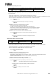
1.1 Connection
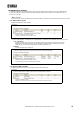
To control one DME
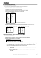
To control multiple DMEs
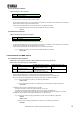
To debug the Remote Controller with a serial control application on a PC such as Hyper Terminal
To use the NETWORK connector for Remote Control with the DME communication protocol
(Not supporting DME64N/24N V3.5 or earlier)
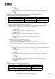
REMOTE connector pin assignment
RS-232C RS-422
Pin Pin Pin Pin
1
Not in use
-
6 DSR In 1
Not in use
-
6 Rx+ In
2 RxD In 7 RTS Out 2 Rx- In 7 RTS Out
3 TxD Out 8 CTS In 3 Tx- Out 8 CTS In
4 DTR Out 9
Not in use
- 4 Tx+ Out 9
Not in use
-
5 GND
-
5 GND
-
The pin 4 and 6 are internally shorted. The pin 7 and 8 are internally shorted.
The pin 7 and 8 are internally shorted.
Available crossover cable wirin
g
s
11
222 2
333 3
444 4
555 5
666 6
777 7
888 8
(interlink cross)
Multiple DMEs can be controlled individually by connecting them as shown below.
Name In/Out Name In/Out Name In/Out Name
Connect the Remote controller/PC to the REMOTE connector on the rear panel of the DME using a RS-232C or a RS-422
crossin
g
cable
(
D-sub; 9
p
in female-to-female
)
.
In/Out
Remote Controller
RS-232C or RS-422
DME
Remote Controller
RS
-
232C
or
RS
-
422
DME 1 (Master)
DME 2
(
Slave
)
RS-232C
DME
Remote Controller
Ethernet
Network
Switch
Remote Controller
Ethernet
Ethernet
DME Remote Control Protocol Specifications V3.1
2