Version 4.
Getting Started with DME Designer In this manual the abbreviation “DME” refers to the DME64N/DME24N/DME8i-C/DME8o-C/DME4io-C/ DME8i-ES/DME8o-ES/DME4io-ES. The abbreviation “DME Satellite” refers to the DME8i-C/DME8o-C/ DME4io-C/DME8i-ES/DME8o-ES/DME4io-ES. Your DME, SP2060, ICP1 and the DME Designer software, let you build a custom audio system installation that can support an incredible variety of conditions.
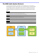
The DME Audio System Network In an audio system including one or more DME units and/or SP2060 units, the “control space” is logically organized using the concepts of “Area”, “Zone”, and “Device Group”. The space covered by the entire system is the “Area”, while independent sonic spaces within that Area are called “Zone”. A group of DME or SP2060 units assigned to the same function are considered a “Device Group”. An Area is comprised of one or more Zones, and each Zone can include up to 32 Device Groups.
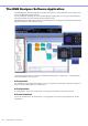
The DME Designer Software Application The DME Designer software application provides a convenient, central interface for the creation and control of DME-based audio systems. By connecting the computer on which the DME Designer application is running to a Group Master it becomes possible to control multiple devices simultaneously. With DME Designer, DME audio systems can be designed and configured via a comprehensive blockdiagram interface on the computer screen.
Scenes A Configuration and its Preset Parameters are a “Scene”.
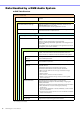
Data Handled by a DME Audio System DME Data Structure Common Overall Data Scene Link Settings Settings required for linked scene operation between multiple groups. Data for Each Device Group User Defined Button Settings Settings required for component parameter control from the DME64N/DME24N or ICP1 panel. Up to 24 parameters can be registered for control. Global Parameter Link Settings Settings required for linked operation of the same types of parameters between multiple devices.
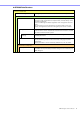
SP2060 Data Structure Common Overall Data Scene Link Settings Settings required for linked scene operation between multiple devices. Data for Each Device Scenes Configurations Local Parameter Link Settings Preset Parameters The information required to switch audio data processing setups. Scenes include configurations and preset data, The last Library name recalled is specified. The Scene Manager facilitates registration and management of scene data.
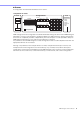
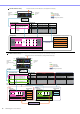
External Device (MIDI, GPI, DAW, AMX/Crestron, controlling DME internal head amp) One DME unit/Device Group Device Group Output Input Microphone Mixer External Head Amp etc... Notes Power Amp Processor etc... Audio signal Control signal Data explanation Setting preset parameters User Defined Button Scene Manager LCD Display Assigned Parameter Dome Low Crossover: Output Low: Level Dome Mid Dome Hi Crossover: Output Mid: Level Crossover: Output High: Level (No Assign) (No Assign) (No Assign) ....
NOTE Separate SP2060 units normally handle scenes independently, but the Scene Link function can be set from the DME Designer to allow linked scene operation. See “Scene Link Manager” on page 151.
Main Changes from V1.0 to V1.1 Main Panel Window • Instead of the former Parameter Link function, there are now two functions: a Global Link function that links parameters within all DMEs in a zone and a Local Link function that links parameters within a single DME unit. (page 94) • The Synchronization function can now not only send data from DME Designer to the DME unit, but can also synchronize by reading data from the DME unit.
Changes from V1.1 to V1.2 Main Panel Window • The synchronization algorithm has been refined for faster synchronization. • Synchronization now can be executed from DME to DME Designer without any break in the sound.
• The order of same-time events can be changed in the Event Scheduler. (page 139) • Exceptions can be specified for Event Scheduler execution day/time. (page 107) • Event Scheduler execution times can be specified in 1-second increments. (page 106) • Head amp gain and Mini-YGDAI Card can be set via GPI, MIDI, User defined Button, DAW Control. • Parameter values, scene recall, GPI output, Wave file playback, and head amp gain can be set via the User Defined Buttons.
• User module port labels can be edited. (page 246) • Graphics can be placed to represent user modules. (page 247) • The Legend field automatically resizes to accommodate project names and titles of different lengths. • A Generic “MY-Others” setting has been provided to accommodate third-party Mini-YGDAI cards. Component Editor Window • Undo and Redo are now shortcut compatible. • A scroll bar appears when the size of the component editor window is reduced.
Changes from V1.2 to V2.0 General • Support added for DME8i-C/DME8o-C/DME4io-C, SP2060 units and MY16-CII. • “Device Groups”, or groups of the same type of device, have been added at the lowest Zone level. • It is now possible to have one master device per device group rather than one master device per zone. This means that it is possible to have multiple master devices in a single zone. • Group masters can now be assigned regardless of the IP address.
• Double-clicking the component name now opens the properties window. • Organization of the Tool Kit window has been changed. (page 198) • A [Draw Image] checkbox that displays or hides the worksheet background image file has been added to the Sheet properties. (page 263) • [Configuration Manager] has been added to the contextual menu that appears when a DME or SP2060 object is right-clicked.
Changes from V2.0 to V3.0 General • DME8i-ES/DME8o-ES/DME4io-ES support. • The DME Designer and DME-N Network Driver installers have been combined, so the appropriate DME-N Network Driver version is now installed automatically with the DME Designer application. • The following connections to the Slave DME units are now possible when a DME Satellite unit is assigned as the Device Group Master: - USB/Ethernet connection to the computer (DME Designer).
Designer Window • It is now possible to set a “clear” background color for text, box, and ellipse objects (page 252, page 254, page 256). • Password entry is now required when opening a User Module Properties dialog box or saving/ exporting in a user module to which security has been applied. • Linked software applications can now be launched from the Slot component contextual menu (page 240).
Changes from V3.0 to V3.5 Component • Program Ducker component added (page 412). • (V3.5.1) During installation it is possible to select and install speaker library data for third-part speakers into the Speaker Processor component library. Main Panel Window • MIDI Setup has been discontinued. Communication ports can now be directly selected via the [Setup] menu [Communication Port] item. (page 155) • (V3.5.
Changes from V3.5 to V3.8 New Features • The DME64N/24N (V3.8x or later) can now be controlled via Ethernet connection from certain external control devices. • The DME64N/24N (V3.8x or later) can now be assigned as the device group master when the device group is formed by combining the DME64N/24N (V3.8x or later) and the DME Satellite. • A new [Show Unconnected Node] button which displays unconnected nodes has been added into the Designer window toolbar.
Changes from V3.8 to V4.0 New Features • The MY4-AEC card can now be selected for I/O card slots. AEC components, which are available when the card is installed, have been added. • The “Partial Recall” function has been added. Scenes can now be recalled on a per component basis. By utilizing both Recall Safe and the new Partial Recall functions, components to be recalled or not recalled can now be selected precisely. • Configurations can now be duplicated in the “Configuration Manager” window.
Contents Getting Started with DME Designer .......................................... 2 SPECIAL NOTICES.................................................................... 2 The DME Audio System Network .............................................. 3 The DME Designer Software Application .................................. 4 Data Handled by a DME Audio System .................................... 6 Main Changes from V1.0 to V1.1............................................. 10 Changes from V1.1 to V1.2 ......
EtherSound Input and Output ............................................... 497 MY-Card ................................................................................ 498 Remote Controlled Head Amp .............................................. 503 Component Glossary............................................................. 505 Appendix 509 Options .................................................................................. 509 Main Display......................................................
Chapter 1 Before Using Installing DME Designer To use DME Designer, you must first install the software on the computer. Before you can connect the DME Designer software to the DME or SP2060 unit, you must first install the USB MIDI Driver or the DME-N Network Driver, according to how you will be connecting, and then make the appropriate settings.
Chapter 1 Before Using 2 Click the [] at the right of the [User] box, and select the user. If no user has been created, only [Administrator] will appear in the list. When starting DME Designer for the first time after installing, select [Administrator]. 3 Enter the password into the [Password] box. Enter the password set for the user. If no password has been set, leave the password box blank when you log on. 4 Click the [OK] button. DME Designer starts up.
Chapter 1 Before Using Closing DME Designer To close DME Designer, click [Exit] on the [File] menu of the Main Panel window. It can also be closed by clicking the [Close] button on the Main Panel window. 1 Click [Exit] on the Main Panel window [File] menu. When you try to close DME Designer, “Project File has been modified. Save?” will be displayed in a dialog box. NOTE Sometimes the “Project File has been modified. Save?” dialog box will not be displayed. 2 To save the file, click [Yes].
Chapter 2 DME Designer Overview Names and Functions of the Windows The DME Designer software has several windows, including the Main Panel window, Designer window, Component Editor window, Resource Meter window, and others. Main Panel Window Designer Window Component Editor Window Resource Meter Window Main Panel Window Menus and buttons are available in the Main Panel window.
Chapter 2 DME Designer Overview Designer Window The Designer window displays several different windows. First among them is the Area window, where you can manage the entire system. The Area window includes one or more Zone windows, which in turn include one or more DME or SP2060 units that are used to build a zones within the area. Next is the Configuration window, where you create the internal configuration of each DME or SP2060 unit.
Chapter 2 DME Designer Overview Zone Window The Zone window is used to design zones within the area. A zone is a more concrete blueprint that includes at least one DME or SP2060. It shows the DME’s connections with other devices and the wiring between them. You can create multiple zones. The DME and SP2060 units and connected devices are arranged in each Zone window, creating configurations.
Chapter 2 DME Designer Overview Toolkit Window The Toolkit window displays the objects that you can use in each window that can be displayed in the Designer window. Those windows are the Area, Zone, Configuration, and User Module windows. The Toolkit displays different objects, according to the currently active window. To place an object in a window, double-click it in the Toolkit window where it is displayed or drag it to the currently active window.
Chapter 2 DME Designer Overview Component Editor The blocks that are arranged in the configuration window are called “components.” When you double-click on a component block arranged in the Configuration window, the Component Editor window will open. There you can edit the parameters for that component. The types of parameters displayed will differ, depending on the component.
Chapter 2 DME Designer Overview Users and Security You can create multiple users in DME Designer and set the functions that are available to each user. Although users who will design and put together installations must be able to use all the functions of DME Designer, users who will only operate the system can be restricted to functions that will not allow them to accidentally change the settings. DME Designer is used with one user at a time logged on.
Chapter 2 DME Designer Overview Logging On The “Log On” dialog box is displayed whenever the application is started or a user is logged off. Whenever one user is already logged on, another user cannot be logged on. To log on as another user, first log off the currently logged on user. NOTE Unless you specifically want to restrict access, we recommend enabling automatic logon. If the access password is forgotten or lost it will not be possible to logon or operate the system.
Chapter 2 DME Designer Overview Logging Off Logoff is used when changing users. When you log off, the document currently being edited is closed, and the “Log On” dialog box is displayed so you can log on the next user. Log off with the [Log Off] command on the [File] menu in the Main Panel window. 1 Click the [File] menu [Log Off] command on the Main Panel window. Log on the next user in the “Log On” dialog box.
Chapter 2 DME Designer Overview Files Used by the DME DESIGNER The following files are used by the DME designer application. Name Description Extension Project File Stores information relating to the entire project. .daf DME Data File Stores information for independent DME or SP2060 units. .ddf Library File Stores component parameters. .cel Stores user control parameters. .ucl Stores user module parameters. .uml Stores user modules. .umf Stores SP2060 libraries. .
Chapter 2 DME Designer Overview Saving Project Files Project files are saved using the [File] menu [Save] and [Save As] commands in the Main Panel window. The [Save] command overwrites the previously saved version of the file. The [Save As] command lets you give a new name to the file before saving it. When you save the file with a new name, you can protect it with a password.
Chapter 2 DME Designer Overview [Save as type] Selects the format for the file you are saving. When saving project files including Wave files set for Wav File Player, select “Project File with wave (*.daf)”. Otherwise, select “Project File (*.daf)”. [Security] Protects files with a password. If you check here, you will be able to enter settings in the [ID], [Password], and [Confirm Password] boxes. [ID] Box Enter the ID that has been set for the file.
Chapter 2 DME Designer Overview Saving Project Files 1 Click [File] menu [Save] in the Main Panel window. If there is a file already saved with the same name, it will be overwritten. When saving a project file for the first time, you must name the file before saving it. The “Save As” dialog box will open, the same as when clicking the [File] menu [Save As] command. Enter a filename and specify the folder where the file will be saved.
Chapter 2 DME Designer Overview Protecting a Project File with a Password When you save a project file with a new name, you can set a password and protect the file. If a password is set, an ID and password will be requested when the file is opened. The security settings for a file cannot be changed by resaving the file with the same name. They can only be changed when saving the file with a new name using the [Save As] command. Once set, the ID and password cannot be changed.
Chapter 2 DME Designer Overview Opening Project Files Project files are opened using the [File] menu [Open] command in the Main Panel window. Since the currently opened project file must be closed before another one can be opened, a “Project file has been modified. Save?” dialog box may be displayed. [Open] Command Project files are opened using the [File] menu [Open] command in the Main Panel window. 1 Click [File] menu [Open] in the Main Panel window. A “Project file has been modified.
Chapter 2 DME Designer Overview Opening a Project File That Has Security Set If security is set for a project, the “Enter ID & Password” dialog box will be displayed when you click the [Open] button in the “Open” dialog box. Enter the ID and password for the file into the [ID] and [Password] boxes, and click the [OK] button. If you enter an incorrect ID or password and click the [OK] button on the “Enter ID & Password” dialog box, the “Wrong ID or password!” dialog box will be displayed.
Chapter 2 DME Designer Overview Double-Click the Icon for the Project File When you double-click the icon for the project file, the file will open. If DME Designer is not started, it will start. After logon, the project file will open. Just as when you use the [Open] command, if DME Designer is already started, the currently open project file must be closed before another one can be opened. Therefore, a “Project file has been modified. Save?” dialog box will be displayed.
Chapter 2 DME Designer Overview DME Data Import This imports DME data file settings into a DME or SP2060 included in the current configuration. 1 Activates the DME or SP2060 configuration layout to be imported. If multiple configurations are available, the DME or SP2060 configuration layout to be imported can be selected via the Navigator window. 2 Click the [File] menu in the Main Panel window, and move the mouse cursor over [Import Device Configuration]. A submenu will be displayed.
Chapter 2 DME Designer Overview [Import Device Configuration] Submenu The device groups included in the current configuration, as well as the DME or SP2060 units included they contain, will be displayed in the [Import Device Configuration] submenu. Select [Create New Group] to create a new device group [Create New DME] creates a new DME and imports settings. NOTE Only users for whom the [Operation Security] [Edit] checkbox in the “Security” dialog box has been checked can import DME data.
Chapter 2 DME Designer Overview DME Data Export This exports parameters from a DME or SP2060 included in the current configuration and saves them as a file. 1 Activates the DME or SP2060 configuration layout to be exported. If multiple configurations are available, the DME or SP2060 configuration layout to be exported can be selected via the Navigator window. 2 Click the [File] menu in the Main Panel window, and move the mouse cursor over [Export Device Configuration]. A submenu will be displayed.
Chapter 2 DME Designer Overview [Export Device Configuration] Submenu The DMEs or SP2060s included in the current configuration will be displayed on the [Export Device Configuration] submenu. Library Files Component Editor, User Control Editor, and User Module Editor parameters can be stored to and recalled from library files. Refer to “Library Files” on page 325. The library data for a single SP2060 unit can be imported or exported as required. Refer to “SP2060 Library Manager” on page 153.
Chapter 2 DME Designer Overview Importing DME Designer All Files NOTE Only users with Administrator access can import DME Designer All files. 1 Click [Import DME Designer All File] in the Main Panel Window [File] menu. Since the imported data will overwrite the existing DME Designer settings, the confirmation message shown below will appear. 2 Click [OK] to continue with the import procedure, or [Cancel] to abort the import. If you click [OK] the “Open” dialog box will appear.
Chapter 2 DME Designer Overview 5 The “Save Project File in DME Designer All File” dialog box will appear, allowing you to save the imported project file. For details on saving project files refer to “Saving Project Files” on page 35. 6 If security is set for the file the “Enter ID & Password” dialog box will appear. Enter your ID and password, and click [OK]. The imported files are stored in the folders listed below. Name Folder Project File Specified in step 5.
Chapter 2 DME Designer Overview Exporting DME Designer All Files 1 Click [Export DME Designer All File] in the Main Panel Window [File] menu. The “Select File for Export” dialog box will appear. Check the checkboxes of the files you want to export. To select all the available files click the [Select All] button, or click [Clear All] to uncheck all the files. NOTE • Only wave and image files used by the currently open project file will be displayed.
Chapter 2 DME Designer Overview Configuration Creation Procedure The configuration is a design diagram that determines the DME configuration. Transferring this data causes the DME to operate. Follow the procedure below to create a DME Designer configuration. SP2060 configurations can be selected from scene preset data, but cannot be edited. NOTE Configurations can be created only when the DME unit is offline. To transfer the data, you must first go into online status.
Chapter 2 DME Designer Overview Online You can connect the DME or SP2060 unit to your computer and transfer configurations, scenes and parameters created in DME Designer into the DME or SP2060 unit. You can also read data from the DME or SP2060 unit into DME Designer, synchronizing it with the status of the DME or SP2060 unit.
Chapter 2 DME Designer Overview 6 Recalling Scenes. When going online, the scene will be recalled. Its scene number must be displayed in [Scene Number], and its scene name will be displayed in Scene Name. If [--------] is displayed of [Scene Name], the scene will be recalled. NOTE Since the SP2060 has scene preset data this confirmation is not necessary. NOTE When the scene device group display mode is “ALL” the scene link name will be displayed. Select a DME group to display the DME group scene name.
Chapter 2 DME Designer Overview 9 IP Address Selection The DMEs and SP2060s included in the current device group are displayed in the [Designer] list in the “Synchronization” dialog box. Click the [IP Address] box, then select the DME or SP2060 unit IP address that matches the DME or SP2060 currently in the DME Designer. NOTE Click [] to display the IP addresses of all similar devices in the area. 10 Going Online.
Chapter 2 DME Designer Overview When going online is finished, the [Go On-line] button will be grayed out, and the Main Panel window [On-line] button will light up. At this point if the [Store Project File into DME after synchronization] item is checked, the project file will be automatically transferred to the DME unit and stored. And if the [Close this window after synchronization] item is checked, the window will close automatically.
Chapter 3 Main Panel Window Names and Functions of the Windows The Main Panel window is the main window of DME Designer. Current Zone Current Device Group Current Configuration Title Bar Menu Bar Tool Buttons (Small) Tool Buttons (Large) Current Scene Log On User [Mute] Button Communication Status Title Bar “DME Designer” is displayed on the title bar. Menu Bar Commands that can be executed in the application are collected into categories on the menu bar.
Chapter 3 Main Panel Window [Save File] Button Saves the project file currently being edited. [Save] on the [File] menu (page 61) [Undo] Button Undoes the most recent edit operation. [Undo] on the [Edit] menu (page 63) [Undo History] Button Opens the “Undo History” dialog box. Undoes multiple operations. [Undo History] on the [Edit] menu (page 63) [Redo] Button Restores operations undone with the [Undo] button back to their original condition.
Chapter 3 Main Panel Window Tool Button (Large) [Synchronization] Button [User Control] Button [Show/Hide Designer] Button [Event Logger] Button [Event Scheduler] Button [Show/Hide Navigator] Button [Show/Hide Designer] Button Displays or hides the Designer window. [Show/Hide Navigator] Button Displays or hides the Navigator window. [User Control] Button Works the same as the [User Control] command on the [View] menu. Clicking this button displays a menu.
Chapter 3 Main Panel Window Current Scene Displays information about the current scene. You can switch between scenes. [Change displayed Scene] (displays DME groups/SP2060s) [Scene Number] [Scene Name] [Scene Manager] Button [Change Display Scene] Selects the information to be displayed. When “All” is selected scene link information is displayed in [Scene Number] and [Scene Name]. When a DME group or SP2060 is selected scene information is displayed in [Scene Number] and [Scene Name].
Chapter 3 Main Panel Window [User] (Logged On User) Currently Logged On User Name [Security] Button Currently Logged On User Name Displays the currently logged on user name. [Security] Button Opens the “Security” dialog box. Current Device Group Displays the name of the currently active device group. Click [] to display a list that allows selection of a different device group. Current Configuration Displays the name of the currently active configuration.
Chapter 3 Main Panel Window Communication Status Displays the status of communication between the group master of the current device group and the computer. Message Transmit/Receive Indicator On-line Button [On-line] Button When the group master of the current device group is connected to a computer, clicking this button alternately switches the unit's on-line/off-line status. The indicator will light when the DME unit is online.
Chapter 3 Main Panel Window Main Panel Window Menu [File] Menu [New] Creates a new project. When a new project is created, the current project will be closed. A confirmation message asking “Project file has been modified. Save?” will be displayed. [Yes] Button Saves the currently open project. If the currently open file was already given a name and saved, that saved file will be overwritten. The “Save As” dialog box will be displayed for files that have not yet been saved.
Chapter 3 Main Panel Window [Open] Opens saved project files. Because the currently open project will be closed, a confirmation message asking “Project file has been modified. Save?” will be displayed. When you select this command, the “Open” dialog box will be displayed. Select the project file you want to open and click the [Open] button. If security is enabled for the project file, the “Enter ID & Password” dialog box will be displayed.
Chapter 3 Main Panel Window [Export Device Configuration] Exports parameters of a device that is arranged in a configuration file. See “DME Data Export” on page 44. DME File Storage Opens the “DME File Storage” dialog box. See “DME File Storage” on page 70. Recently Used Files Displays recently saved files. If you click one of the file names, you can open that file. [Preferences] Opens the “Preferences” dialog box. See “Preferences” on page 72.
Chapter 3 Main Panel Window [Edit] Menu [Undo] Undoes a single operation. The name of the operation that will be undone by [Undo] is displayed in the command name. You can also select the commands that come after that. When [Undo] is not possible, the command will be grayed out. [Redo] Returns to the status before the [Undo] command was executed. The name of the operation that will be restored by [Redo] is displayed. You can [Redo] only as many operations as were undone with the [Undo] command.
Chapter 3 Main Panel Window [View] Menu [Designer] Displays or hides the Designer window. [Event Logger] Displays the network event log. Not displayed if selected while the network event log is showing. See “Event Logger” on page 75. [User Control] This opens User Control. The user controls that can be opened by the currently logged on user are displayed on a submenu. If you click [New User Control] on the submenu, the “New User Control” dialog box opens.
Chapter 3 Main Panel Window [Tools] Menu [Scene Manager] Opens the “Scene Manager” dialog box. See “Scene Manager” on page 82. [User Control Manager] Opens the “User Control Manager” dialog box. See “User Control” on page 91, page 325. [Parameter Link] Opens the “Parameter Link” window. See “Parameter Link” on page 94 [Synchronization] Opens the “Synchronization” dialog box. See “Synchronization (DME Designer and Unit Synchronization)” on page 97.
Chapter 3 Main Panel Window [MIDI] Opens the “MIDI” dialog box. See “MIDI” on page 125. [User Defined Button] Opens the “User Defined Button” dialog box. See “User Defined Button (User Defined Parameters)” on page 132. [DAW Control] Opens the “DAW Control” dialog box. See “DAW Control” on page 136. [Remote Control Setup List] Opens the “Remote Control Setup List” Dialog box. See “Remote Control Setup List” on page 139. [Internal HA Control] Opens the “Internal HA Control” dialog box.
Chapter 3 Main Panel Window [Setup] Menu [Communication Port] Opens the “Communication Port” dialog box. See “Communication Port Setup” on page 155. [Shortcut Keys] Opens the “Shortcut Keys” dialog box. See “Shortcut Keys” on page 156. [Security] Opens the “Security” dialog box. See “Security (Creating Users and Making User Settings)” on page 157. [Hardware] Menu [Network Setup] Opens the “Network Setup” dialog box. See “Network Setup” on page 165.
Chapter 3 Main Panel Window [Monitor Out] Opens the “Monitor Out” dialog box. See “Monitor Out” on page 179. [Clock] Opens the “Clock” dialog box. See “Clock” on page 180. [Language] Opens the “Language” dialog box. See “Language Settings” on page 182. [Backup] Opens the “Backup” dialog box. See “Backup” on page 183. [SP2060 Backup] Opens the “SP2060 Backup” dialog box. See “SP2060 Backup” on page 184 [Firmware Update] Updates the DME, SP2060, or ICP1 firmware.
Chapter 3 Main Panel Window [Window] Menu Displays the open windows. Click a window name to bring that window to the front. [Close All Editor Windows] Closes all editor windows. NOTE Each design windows within the Designer window can be switched using the [Window] menu in the Designer window. [About] Menu [About DME Designer] Displays information about this application.
Chapter 3 Main Panel Window DME File Storage Allows management of DME files. Project files can be managed on the DME, eliminating the need to manage them on the computer. Project files can be managed on a DME unit without the need for a computer. Since project files are necessary to allow synchronization of DME and SP2060 units, we recommend that you save your project files to the DME unit for enhanced reliability. Click [DME File Storage] in the [File] menu to display the “DME File Storage” dialog.
Chapter 3 Main Panel Window Replacing the DME64N/24N startup screen The screen image appearing when the DME64N/24N starts up can be replaced with a graphic file of your choice in the following way. This function allows you to display a desired startup screen-for example, one that includes your facility's name and logo. Preparing the graphic data Create the desired graphic data at a size of 160 x 48 dots in black-and-white bitmap format (extension .bmp) and save it as a file with the name “opening.bmp.
Chapter 3 Main Panel Window Preferences When you click the [Preferences] command on the [File] menu in the Main Panel window, the “Preferences” dialog box is displayed. Here you can make environmental settings for using DME Designer. Names and Functions [Application] Tab Here you can set the general usage environment. On Startup Selects the action when the application starts up or a user logs on. • [Load the last file opened] Opens the last opened file.
Chapter 3 Main Panel Window Auto Save Set up the automatic file save feature. This setting has no effect when the file being worked on has not previously been saved, or the computer is online. • [Enable] Auto save of project files being worked on will occur when checked. The file will be overwritten, but the Undo history will not be cleared. • [Interval in minutes] Specifies the auto-save interval in minutes.
Chapter 3 Main Panel Window Slider Mode Sets the action that occurs when you click on the scale located under the sliders. • Ramp When the fader bar is clicked the knob will move a preset amount in the corresponding direction. • Touch The slider does not move without directly touching it, even if you click the mouse button. • Jump The slider jumps to the location where you click. Edit Box Zoom When “On” the edit box will enlarge on mouse-over.
Chapter 3 Main Panel Window Event Logger Click [Event Logger] in the [View] menu to open the “Event Logger” window. This window displays the DME unit event log, and it allows specifying the log file to be stored on the computer as well as the log file to be store in the DME unit. If the window is opened while online the event log is automatically retrieved from the DME unit and displayed as a list in the “Event Logger” window.
Chapter 3 Main Panel Window DME List • [Date] Displays the date the event occurred. (Example Display: 2004-08-24) • [Time] Displays the time the event occurred. • [Type] Displays the event type and icon. There are three event types: (Warning): Warning event (Error): Error event (Information): Other events • [Zone] Displays the name of the zone in which the event occurred. • [Group] Displays the name of the device group in which an event has occurred.
Chapter 3 Main Panel Window “Log Setup” dialog box Click the [Log Setup] button in the “Event Logger” window to display the “Log Setup” dialog box. Here you can make Event Log settings. These settings apply to the system as a whole. [Enable Logging] Turns the function that writes the event log to a file ON or OFF. When the checkbox is checked the event log is saved to a file, and the saved event log is cleared from the DME unit. If the checkbox is unchecked the DME event log is saved in the DME unit.
Chapter 3 Main Panel Window [OK] Button Applies any setting changes and closes the window. [Cancel] Button Closes the window without changing any settings. “Get Log” dialog box Click the [Get Log] button in the “Event Logger” window while offline to open the “Get Log” dialog box. The event log can be retrieved from the DME unit while offline and saved as a file on the computer. DME List Displays the IP addresses and types of DME units included in the device group.
Chapter 3 Main Panel Window “Event Log List” Dialog Box Click the [Log List] button in the “Log Setup” dialog box to open the “Event Log List” dialog box. This allows selection of the events to be stored in each DME unit. Events not selected here will not be saved either in the DME unit or to a log file. [Zone] If you click here, a list will be displayed. Specifies a zone. [DME] If you click here, a list will be displayed. Specifies DMEs. [Event] Selects the events to be logged.
Chapter 3 Main Panel Window Event Log List The event logs that can be retrieved from the DME unit as well as their content and countermeasures are listed below. Displayed Messages 80 Contents/Countermeasures Communication between PC and DME ended. Communication between the computer and DME (device group master) has stopped. Check cable connections and router/hub operation. Communication between PC and DME started. Communication between the computer and DME (device group master) has started.
Chapter 3 Main Panel Window Displayed Messages Contents/Countermeasures Communication between DME is busy and load is applied. Heavy network traffic is causing communication delays. Check the devices connected to the network. It may be advisable to reduce the number of devices connected to the network. If the current link mode is 10Base-T, it may be advisable to upgrade to 100Base-TX No Battery. The backup battery is completely depleted or not connected.
Chapter 3 Main Panel Window Scene Manager Scenes Configuration contents can be given a name and saved as “Scenes.” Saving scenes is called “Scene Store.” Parameter settings in the configuration for each site used can be stored multiple times and recalled and used when needed. There are 999 scene memories available. When a scene is stored, DME and SP2060 parameters are saved as “preset parameters.” Presets are automatically created when a scene is stored.
Chapter 3 Main Panel Window Names and Functions [Copy] Button [Cut] Button [Insert] Button [Paste] Button [Recall Settings] Button [Clear] Button List [Scene Link] Button [Detail] Button [Store] Button [Recall] Button DME Group/SP2060 Selection Selects a DME group or SP2060. NOTE The selected DME group or SP2060 is linked with the current device group. List Displays the contents of the scene. Scene No. Displays the scene number. Click here to select a scene.
Chapter 3 Main Panel Window Configuration Displays the configuration name. If the scene has not been stored, a hyphen (-) will be displayed. Edit Security Displays the scene edit security levels. Clicking here will display a list where you can change these security levels. Only levels at or below the security level of the currently logged on user are displayed in the list. Scenes are stored with the same security level as the user, but their store and edit security levels can be set lower if required.
Chapter 3 Main Panel Window Fade Time Sets the fade time: i.e. the time it will take fader parameters to reach their new settings when a scene is recalled. The changes are smooth and continuous. If only the presets in the recalled scene are set when that scene is recalled, the volume will be adjusted while the sound from the previous scene is playing, until the new level is reached If the configuration also changes, the volume will rise from silence until it reaches the new value.
Chapter 3 Main Panel Window [Clear] Button Deletes the contents of the scene selected on the list. The button will be grayed out and cannot be used when the DME unit is online or when an SP2060 preset is being used. If the preset parameters included in a scene are not used in another scene, a “Delete preset?” message will be displayed. If the preset parameters are not needed, click the [OK] button. If you click the [Cancel] button, the preset parameters will not be deleted.
Chapter 3 Main Panel Window • Component Tree Displays all components included in the scene. Check the checkboxes to the left of the components that you do not want to recall when a scene is recalled. NOTE Components that are checked in the [Recall Safe] tab component tree will not be recalled. If you want all components to be recalled there is no need to make any settings in this tab.
Chapter 3 Main Panel Window Click the [Add] button to create a new set with all components selected. Click the [Delete] button to delete the currently selected set from the list. Right-clicking in the Partial Recall list displays a contextual menu that provides access to the following operations: Add: Add a new set with all components selected (same function as the [Add] button). Delete: Deletes the currently selected set (same function as the [Delete] button).
Chapter 3 Main Panel Window [Store] Button Stores the contents of the current configuration into the scene selected in the list. If an empty scene is selected and the contents stored there, a new scene is created. If a scene is already stored in the selected scene number, it will be overwritten. If [Confirm Scene Store] is checked on the [Application] tab of the “Preferences” dialog box, a confirmation message will be displayed before the scene is stored.
Chapter 3 Main Panel Window Preset parameters List Displays the preset parameters for each DME unit in the scene selected in the list. When another scene is selected on the list, the contents of the preset parameters list will be changed. You can change the preset parameters used in the scene by clicking the radio buttons to the left of the preset parameters names. You can also create, delete, and store preset parameters or change their names. DME Displays the DME.
Chapter 3 Main Panel Window User Control User Controls You can create an original control by arranging knobs and sliders in the component editor. Controls you create are called “user controls.” Those created user controls are displayed in the [View] [User Control] submenu in the Main Panel window Refer to “User Control Editor/User Module Editor” on page 325 for information on user control editing.
Chapter 3 Main Panel Window Name Displays the names of the user controls. Clicking here will select the characters in the name, allowing you to change it. Security Level Displays the security level set for each user control. Clicking here will display a list where you can change the security level. User Displays the name of the user specified in User Control. Clicking here will display a list of the available users.
Chapter 3 Main Panel Window [New] Button Creates new user controls. Clicking here displays the “New User Control” dialog box. Enter the User Control name in the [Name] box. [User Level]/[User Name] Use the radio buttons to the left to select security-level or user dependent control. • [User Level] Select a security level from the drop-down list. • [User Name] Check a checkbox. Click [OK] to create the specified User Control setup.
Chapter 3 Main Panel Window Parameter Link About Parameter Links You can group parameters of the same type and link them. These groups are called “Parameter Links.” When one parameter in a parameter link group is changed, all parameters in the parameter link group will change in the same way. There are three parameter link types: global links, local links and component links. Global links link parameters for DMEs within a device group.
Chapter 3 Main Panel Window • Local Link Links to the parameters of one DME unit. NOTE When a scene is recalled using Recall Safe or Partial Recall settings (page 86), linked parameters will be recalled with the same settings. • Component Link Links component parameters of the same type within a single DME unit. NOTE When a scene is recalled using Recall Safe or Partial Recall settings (page 86), linked parameters will be recalled with the same settings.
Chapter 3 Main Panel Window • Keep Offset Click to urn ON or OFF. When “ON” the parameter offset is maintained so that when any parameter in the group reaches its minimum or maximum value, further decrease or increase is not possible. Keep Offset for multiple parameters can be turned ON or OFF via the contextual menu that appears when the group name is right-clicked. • Parameter Displays the parameters that belong to a parameter link group.
Chapter 3 Main Panel Window Synchronization (DME Designer and Unit Synchronization) The DME or SP2060 unit and DME Designer are synchronized by Synchronization. The DME or SP2060 operates according to the configuration and scene information transferred during this process. This Synchronization is used when transferring the configuration in DME Designer and when controlling the DME or SP2060 unit in real time.
Chapter 3 Main Panel Window “Synchronization” Dialog Box When you click the [Synchronization] command on the [Tools] menu, the “Synchronization” dialog box is displayed. The data from the current device group in the Designer is synchronized with the DME or SP2060 unit. Here you can make settings for synchronizing the unit in DME Designer one-on-one with the DME or SP2060 that actually exists on the network.
Chapter 3 Main Panel Window [Group] List Allows selection of a device group to be synchronized. [Go On-line] Button This button will be grayed out when the software is online. Clicking the button displays a dialog box where you can decide the synchronization method. [DME Designer Device] button A consistency check is performed between the data in the current device group and the DME or SP2060 data, then the communication status changes to online.
Chapter 3 Main Panel Window Designer The Designer list displays DME or SP2060 units arranged in the currently valid device group in the DME Designer. The unit in the DME Designer is matched with a recognized IP address, and they are compared one-to-one. Device Name IP Address Select Box DME Name Displays the names of DME or SP2060 units included in the project. When multiple DMEs and SP2060s of the same type are arranged in a zone window, it is a good idea to change the name of each one.
Chapter 3 Main Panel Window Event Scheduler “Event Scheduler” Dialog Box When you click [Event Scheduler] in the [Tools] menu, the “Event Scheduler” dialog box is displayed. This sets the scheduling for events. You can schedule events by specifying the date, time, and the action to execute. You can set up schedules for events to be executed at a specified time, and events that are to be repeated periodically. Periodic events are those that repeat each year, month, week, or day.
Chapter 3 Main Panel Window [Operation] Displays the function that will be executed when the event starts. [Date] Displays the event start date. Periodic events are displayed as shown below, with an icon and text that indicate a periodic event. • [January 1 every year] Each New Year's Day • [First Monday of January every year] First Monday in January each year • [Day 1 every month] First day of each month • [Second Monday of every month] The second Monday of each month.
Chapter 3 Main Panel Window [Clock setup] Button Opens the “Clock” dialog box to set the DME internal clock. See “Clock” on page 180. [Apply] Button Applies any current setting changes. [OK] Button Applies any setting changes and closes the window. [Cancel] Button Closes the window without changing any settings. [Add Event (Edit Event)] Dialog Box The dialog box is displayed when you click on the [Add] or [Edit] button in the “Event Scheduler” dialog box.
Chapter 3 Main Panel Window [Event Operation] Set the operation that is executed when the event starts. [Operation] When you click this button, a list of events is displayed. Specify the operation that is executed when the event starts. The following four items are on the list: • [Scene Change] Changes the scene. • [Parameter Value Edit] Changes a parameter. NOTE If user module security is enabled, the components are not displayed.
Chapter 3 Main Panel Window [Component] Select the component that has the parameter to be changed. The list displays the components arranged for the DME that is selected in the [DME Unit] box. [Parameter] Select the parameter that will change. Parameters for the component that is selected in the [Component] box are displayed in a list. [Value] Set a value for the parameter. Change the parameter using the spin buttons or the slider on the right.
Chapter 3 Main Panel Window [Event Schedule] Set the year/month/date to start the event. Calendar Sets the date the event will start. Change the year and month using the [<] and [>] buttons. Click on a day to set that date. February 29 can be set on the calendar, where it appears every four years (each leap year). [Time] Sets the time the event will start. Click the hour and minute, then set numerical values using the spin boxes. Only the time is set for periodic events.
Chapter 3 Main Panel Window [Event Exceptions] Specifies “exception” year/month/day and time settings at which events will not be executed. The available settings will depend on the event cycle. • When the event cycle is [Year] Only the [Year] setting is available. • When the event cycle is [Month] Only the [Month] and [Week] setting is available. • When the event cycle is [Week] Only the [Month], [Week] and [Day] settings are available.
Chapter 3 Main Panel Window Wav File Manager When you click [Wav File Manager] on the [Tools] menu, the “Wav File Manager” dialog box is displayed. Here you can manage playback settings for Wave files played in the Wav File Player. This is set for each DME. The setting can be made only when in offline status. Up to 100 Wave files can be managed. If a Wave file is added that exceeds the memory limit, a warning message will be displayed.
Chapter 3 Main Panel Window [Wave File] Displays the Wave file information. Settings can be made here as well. [No.] The Wave file number is displayed in the leftmost column. Numbers are added from the top in order. [List Name] You can set up to 27 characters as a label separate from the Wave file name. The Wave file name is displayed here by default. [File Name] Up to 31 characters are displayed as the wave file name. [Size] Displays Wave file size information.
Chapter 3 Main Panel Window [Recall] Button Reads a saved library. Clicking this button displays a menu. A menu displays library files saved in the folder that has been set as the Contents Folder. Click the library to be read. [Open File Dialog] Displays the file select dialog box. You can select a library file that is saved in the folder set as the Contents Folder, and read it. [Add] Button When you click here, External Input and the file select list is displayed.
Chapter 3 Main Panel Window [Remove] Button Deletes settings from the selected line. This button is grayed out when no Wave file is selected in the list. [Move Up] Button Moves the selected line up one. It is switched with the line immediately above. The button will be grayed out if nothing is selected in the list, or if [No. 1] is selected in the list. [Move Down] Button Moves the selected line down one. It is switched with the line immediately below.
Chapter 3 Main Panel Window GPI About GPI GPI is an abbreviation for General Purpose Interface. Using GPI input and output, DMEs can be remotely controlled from custom-made controllers or external equipment. The number of GPI ports depends on the type of device. Sets GPI input/output for each DME. Using GPI input data, you can switch DME scenes and change component change component parameters. Refer to the DME owner’s manual for information on making GPI connections and other hardwarerelated issues.
Chapter 3 Main Panel Window Control Source Selection via a CP4SW A CP4SW control panel connected to the GPI terminal can be used to switch the channel source of Source Selector (Position 4) components. Assign the Source Selector component's Position parameter via the Parameter Value Edit function in the GPI IN and GPI OUT fields and set the parameter values ([Max] in the GPI IN field, and [Threshold] in the GPI OUT field) to 1 through 4 for the corresponding ports.
Chapter 3 Main Panel Window [DME] From the list, select the DME where you will be making settings. Configuration The current configuration name will be displayed. GPI IN The DME64N has 16 GPI IN channels, and the DME24N/DME Satellite has 8 GPI IN ports. These settings determine which DME parameters will be controlled by input received at each individual GPI IN port. The port numbers are shown in the leftmost column. [Function] Specifies the function to be controlled by GPI input.
Chapter 3 Main Panel Window The parameter value changes in proportion to the voltage applied to the GPI input. The minimum voltage applied to GPI IN will produce the specified [Min] parameter value, and the maximum voltage applied to GPI IN will produce the specified [Max] parameter value, with intermediate voltages produced the corresponding intermediate parameter values. Example: Relationship between the voltage applied to GPI IN and the Fader Level when [Fader Level] is set in the [Parameter] box. Max.
Chapter 3 Main Panel Window • [Scene Change] GPI input can be used to recall a specified scene. [Parameter] specifies the number of the scene to be recalled. [Min] and [Max] are not available. [Terminal] determines how the GPI input voltage will affect the specified parameter. The scene specified by [Parameter] will be recalled each time the voltage applied to GPI IN rises from below to above the median voltage.* Max. voltage applied to GPI IN Median voltage Min.
Chapter 3 Main Panel Window • [Scene Decrement] GPI input can be used to decrement the scene number. [Parameter], [Min], and [Max] are not available. [Terminal] determines how the GPI input voltage will affect the specified parameter. The scene number will be decremented each time the voltage applied to GPI IN rises from below to above the median voltage.* Max. voltage applied to GPI IN Median voltage Min.
Chapter 3 Main Panel Window • [Mute] GPI input can be used to engage or disengage the DME mute function. [Parameter], [Min], and [Max] are not available. [Terminal] determines how the GPI input voltage will affect the specified parameter. Mute will be ON when the voltage applied to GPI IN is above the median voltage*, and OFF when the voltage is below the median. Max. voltage applied to GPI IN Mute ON Median voltage Mute OFF Mute OFF Min.
Chapter 3 Main Panel Window • [GPI Lock] GPI Lock can be turned on or off via GPI input. When GPI Lock is ON, all GPI inputs other than the one being used for GPI Lock control are locked and input will be ignored. [Parameter], [Min], and [Max] are not available. [Terminal] determines how the GPI input voltage will affect the specified parameter. GPI lock will be ON when the voltage applied to GPI IN is above the median voltage*, and OFF when the voltage is below the median. Max.
Chapter 3 Main Panel Window • [Time Adjustment] GPI input can be used to adjust the DME internal clock as follows: Internal clock time Time after adjustment 0~14 seconds Returned to 0 seconds 15~29 seconds Advanced to 30 seconds 30~44 seconds Returned to 30 seconds 45~59 seconds Advanced to 0 seconds [Parameter], [Min], and [Max] are not available. [Terminal] determines how the GPI input voltage will affect the specified parameter.
Chapter 3 Main Panel Window • [Play Wav File] GPI input can be used to initiate playback of the specified Wave file. [Parameter] specifies the Wave file to be played. Files specified by the Wav File Manager can be selected. Wave files can only be selected if a Wav File Player is included in the DME configuration. [Min], and [Max] are not available. [Terminal] determines how the GPI input voltage will affect the specified parameter.
Chapter 3 Main Panel Window GPI OUT The DME64N has sixteen GPI OUT ports, the DME24N has eight, and the DME Satellite has four. These settings determine which DME parameter values will be output via each individual GPI IN ports. The ports numbers are shown in the leftmost column. [Function] Specifies the function to be transmitted via a GPI output. The six available functions are: [No Assign], [Parameter Value Edit], [Scene Change], [GPI Lock], [Direct Parameter Value], and [Audio Detector].
Chapter 3 Main Panel Window • [Scene Change] The recall status of the specified scene is transmitted via GPI output. [Parameter] specifies the scene for which the recall status is to be output. [Threshold] and [Polarity] are not available. [Terminal] determines how the GPI voltage will be output in response to parameter changes. Terminal GPI Output When the current scene is the same as the scene specified by [Parameter] the output will be high, and when different the output will be low.
Chapter 3 Main Panel Window Terminal Polarity GPI Output Pulse waveform 2 (*2) is output when the status changes from no audio signal detected to audio signal detected. Pulse waveform 2 (*2) is output when the status changes from audio signal detected to no audio signal detected. *1 Pulse waveform 1 *2 Pulse waveform 2 HI HI LO LO 250msec 250msec Event Scheduler Event Schedule is shown when [GPI OUT] is set in “Event Scheduler.” See “Event Scheduler” on page 101.
Chapter 3 Main Panel Window MIDI When you click the [MIDI] command on the [Tools] menu, the “MIDI” dialog box is displayed. Here you can make remote control and other settings. NOTE Does not apply to SP2060 units Names and Functions Common to All Tabs DME From the list, select the DME where you will be making settings. [OK] Button Applies any setting changes and closes the window. [Cancel] Button Closes the window without changing any settings.
Chapter 3 Main Panel Window [Control Change] Tab Assigns components to control change for each DME. You can change DME parameters by sending control change messages from external equipment. You can assign to control change numbers 1-31, 33-95, and 102-119. NOTE Because control change numbers 0 and 32 are used for bank select MSB, numbers 96-101 are RPN/NRPN related, and 120-127 are used for mode messages, they cannot be used for component assignment.
Chapter 3 Main Panel Window Parameter Set the assigned component link parameter. When you click here, a list of parameters included in the component is displayed. Select the parameter you want to assign. Min/Max Sets the range of operation for the parameter. The current values for the [Min] (lower limit) and [Max] (upper limit) are displayed. If you click here, a slider will be displayed. The range and parameter units that can be set will vary, depending on the parameter selected in the [Parameter] box.
Chapter 3 Main Panel Window [Program Change] Tab Assigns scenes to program control change numbers 1 through 128. Switches scenes when program changes are received. These settings are shared by all DMEs in the device group. Up to 999 assignments can be made. Scenes above number 128 are assigned by changing banks. Program Change Event Program numbers and the scenes assigned to them are displayed in a list. No. This displays program numbers from 1 to 128.
Chapter 3 Main Panel Window [Assign All] Button Assigns all scenes in order starting from program number 1. Bank Select LSB The bank is changed when assigning scenes numbered 129 and higher. Eight banks can be used, numbered from zero to seven. Click the [] and select the bank where you will make settings. [Parameter Change] Tab Specifies the parameter to be controlled by parameter change commands for each address. Up to 128 can be set.
Chapter 3 Main Panel Window Parameter Change List The current settings are displayed in the list in the center. No. This displays the parameter change numbers. Component Assigns components. If you click here, a list will be displayed. Assignable components are on the list. Click the component name to select it. Parameter Set the assigned component link parameter. When you click here, a list is displayed of parameters included in the component selected in the [Component] box.
Chapter 3 Main Panel Window Min/Max This sets the parameter range. The current values for the [Min] (lower limit) and [Max] (upper limit) are displayed. The range and units that can be set will vary, depending on the parameter selected. If you click here, a slider will be displayed. You can change the parameter by dragging the slider. To make a finer setting, press the key while dragging the slider. The value for the parameter will be shown while you are dragging the slider.
Chapter 3 Main Panel Window User Defined Button (User Defined Parameters) User Defined Parameters Parameters that the user can operate using function keys through in the DME64N/24N unit or ICP1 are called “User Defined Button.” Frequently changed parameters can be assigned in advance to any of 24 (four pages times six) presets, and operated on the DME64N/24N unit or ICP1 even if DME Designer is not being used.
Chapter 3 Main Panel Window Function Specifies the function to be assigned to the function keys. • [No Assign] No assignment. Select this option to clear an assigned function. • [Parameter Value Edit] Allows the parameter specified in the [Parameter] field to be changed. NOTE Components for user modules are also listed in a hierarchal display, but if user module security is enabled, the components are not displayed. However, parameters displayed in the user module editor are displayed here.
Chapter 3 Main Panel Window Parameter Sets the parameter assigned to each function key. If you click here, a list will be displayed. This list displays the parameters that are included in the current configuration. Select the parameter you want called by the function key. LCD Display Sets the text displayed on the DME unit or ICP1. Click the [LCD Display] box and enter text. Up to 23 characters can be entered into the [LCD Display] box.
Chapter 3 Main Panel Window Setting User Defined Parameters Set the user defined parameter. 1 Create a configuration. 2 Click [User Defined Button] in the [Tools] menu. The “User Defined Button” dialog box will be displayed. 3 Click one of the tabs numbered [1] through [4] to select the set of user defined parameters you will assign your parameters to. The four tabs correspond to the pages on the DME unit or ICP1 main screen.
Chapter 3 Main Panel Window DAW Control When you click [DAW Control] on the [Tools] menu, the “DAW Control” dialog box is displayed. Here you can make settings for when the DME64N/24N is controlled from a DAW controller. This is set for each zone configuration. The setting can be made only when in offline status. NOTE DAW Control can be set on DME64N/24N units only. NOTE DAW control editing can be performed only by users for whom the [Edit] security checkbox has been checked.
Chapter 3 Main Panel Window [Function] Selects the function that will be changed by the DAW controller. If you click here, a list will be displayed. • [No Assign] Makes no assignments. Select this when you are erasing an already set assignment. • [Parameter Value Edit] Allows the parameter of the component specified in the [Parameter] field to be changed. NOTE Components for user modules are also listed in a hierarchal display, but if user module security is enabled, the components are not displayed.
Chapter 3 Main Panel Window [Controller] Selects a controller from the list when [Parameter Value Edit] is set in [Function]. [Switch], [Fader], or [Knob] can be selected. [Label] Enter a label. Double-click to enter the text. You can enter up to 16 characters of text. Set the value with the key, or cancel it with the key. NOTE If [Scene Change], [Scene Increment], [Scene Decrement], [Mute], or [GPI Lock] is selected for [Function], the label name is fixed.
Chapter 3 Main Panel Window Remote Control Setup List When you click the [Remote Control Setup List] command on the [Tools] menu, the “Remote Control Setup List” dialog box is displayed. Registers the parameters to be controlled from an external controller. NOTE DME V3.8 or later/DME Satellite units allow remote control via the [NETWORK] connector as well as via the [REMOTE] connector. The port to be used is specified via the “Remote” tab of the “Utility” dialog box (page 172).
Chapter 3 Main Panel Window [Min]/[Max] Displays the minimum and maximum values for the parameter. [Type] Selects a fader curve when level, etc., is select for [Parameter]. Select [dB] to directly control the level in dB, or [Curve Table] to use one of the DME fader curves for level adjustment. [Clear] Button Clears the selected row. [String Display]/[Numeric] Buttons Switches the parameter value display format. String Display: The value displayed in the editor windows. Numeric: The internal value.
Chapter 3 Main Panel Window Internal HA Control The gain and phantom power (+48V) of the DME24N/DME8i-C/DME4io-C/DME8i-ES/DME4io-ES internal head amplifiers can be controlled from a PM5D, and LS9 or other compatible mixing console. The digital mixer communicates serially with one DME unit in a device group, and that DME unit controls all other DME units in the group. Only one DME unit in a device group may be connected to a digital mixer for direct serial communication.
Chapter 3 Main Panel Window Remote Connection Connect the digital mixer to the [REMOTE] connector of one of the DME units, and set the port to be used for head amp control to “Remote” via the [Internal HA Control] parameter in the “Remote” tab in the “Utility” dialog box (page 172). Use an Ethernet cable connected to the [NETWORK] connectors to make connections between DME series units.
Chapter 3 Main Panel Window CobraNet Connection Use a CobraNet interface card such as the MY16-CII to make CobraNet connections between the digital mixer and DME units. Use an Ethernet cable connected to the [NETWORK] connectors to make connections between DME series units. The port to be used for head amp control is specified via the [Internal HA Control] parameter in the “Remote” tab in the “Utility” dialog box (page 172).
Chapter 3 Main Panel Window EtherSound Connection Digital Mixers Without a [REMOTE] Connector Use an EtherSound interface card such as the MY16-ES64 to make EtherSound connections between the digital mixer and DME units. Use an Ethernet cable connected to the [NETWORK] connectors to make connections between DME series units.
Chapter 3 Main Panel Window Digital Mixers With a [REMOTE] Connector Connect the mixer’s [REMOTE] connector to the MY16-ES64 or similar EtherSound interface card via a 9-pin D-sub cross cable, and make the appropriate EtherSound connections between the interface card and DME units. Use an Ethernet cable connected to the [NETWORK] connectors to make connections between DME series units.
Chapter 3 Main Panel Window Setting the Internal Head Amp ID Click [Internal HA Control] in the [Tools] menu to open the “Internal HA Control” dialog box. ID numbers for the internal DME head amplifiers that are to be controlled from the digital mixer are assigned via this dialog box. The ID numbers are displayed as AD8HR IDs on the digital mixer. Click on a [Device Label] field and select the target DME unit from the drop-down menu that appears. Device Group Select Field Selects the target device group.
Chapter 3 Main Panel Window Parameter List When you click [Parameter List] in the [Tools] menu, the “Parameter List” dialog box is displayed. A list of parameters in the current configuration of the current zone are displayed. Here you can check things like the parameter IDs. You can also print the list of parameters. When the dialog box is opened or when a DME is selected from the [DME] list, the parameter values are displayed. NOTE Does not apply to SP2060 units.
Chapter 3 Main Panel Window [Preview] Button Prints a list of parameters. When you click this button a preview screen is displayed. [Save] Button Saves the parameter list as a CSV file. When you click this button, the standard operating system save dialog box is displayed. NOTE The CSV format is a comma delimited text file that can be read by many types of software, such as word processor, spreadsheet, or database programs.
Chapter 3 Main Panel Window [Setup] Button Clicking here displays the “Print Setup” dialog box. Here you can set the paper size, paper orientation, and font. [Paper Size] Select the paper size from the list. [Orientation] Set the orientation of the paper by clicking one of the radio buttons. • [Portrait] Prints on the paper with it oriented vertically. • [Landscape] Prints on the paper with it orientated horizontally. [Font] Displays the set font.
Chapter 3 Main Panel Window Component Lock Click [Component Lock] in the [Tools] menu to display the Component Lock dialog.] NOTE Does not apply to SP2060 units Names and Functions The component/user module names included in the DME will be displayed. AD and Slot will also be displayed.
Chapter 3 Main Panel Window Scene Link Manager Either click the [Scene Link Manager] item in the [Tools] menu, or the [Scene Link] button the “Scene Manager” window to open the “Scene Link Manager” window. “Scene Link Manager” Window This window allows setup and recall of scene linking between DME groups and SP2060 units. Scene linking makes it possible to simultaneously recall scenes on multiple DME groups and/or SP2060 units. Up to 999 scene link setups can be specified.
Chapter 3 Main Panel Window [Delete] Button Deletes the scene link setup currently selected in the scene link tree view. When clicked an “Are you sure?” dialog will appear. Click the [Yes] button to delete the selected scene link setup. Click the [No] button to abort the scene link delete operation. The [No] button will be grayed out and inoperable if a scene link setup is not selected. [Copy] Button Copies the selected scene link setup.
Chapter 3 Main Panel Window SP2060 Library Manager Click the [SP2060 Library Manager] item in the [Tools] menu to open the “SP2060 Library Manager” window. “SP2060 Library Manager” Window Allows editing of SP2060 Speaker Processor component libraries. Up to 60 libraries can be stored for each component, and up to 360 libraries can be stored for each SP2060 unit NOTE Only users with security status in which [Edit] is checked can edit this feature.
Chapter 3 Main Panel Window [Delete File] Button Deletes the selected library from the library list. When this button is clicked an “Are you sure?” dialog box will open. Click the [YES] button to delete the selected library. Click the [NO] button to abort the library delete operation. The [Delete] button will be grayed out and inoperable if a library is not selected. [Move UP] Button Moves the currently selected library up one position in the library list.
Chapter 3 Main Panel Window Communication Port Setup Click the [Communication Port] item in the [Setup] menu to open the “Communication Port” dialog box. In this window you can set the communication port of the master current device to be used by the DME Designer. NOTE Selects either the USB-MIDI Driver or DME-N Network Driver for the communication port. Refer to the “DME Setup Manual” for driver installation and setup instructions.
Chapter 3 Main Panel Window Shortcut Keys Click [Shortcut Keys] in the [Setup] menu to display the “Shortcut Keys” dialog. Names and Functions Click to select the desired shortcut item. [Enter New Key] If assigned, the current shortcut will be displayed. A shortcut entered via the computer keyboard will be displayed. [OK] Button Enters the settings and closes the dialog box. [Cancel] Button Closes the dialog box without entering the settings.
Chapter 3 Main Panel Window Security (Creating Users and Making User Settings) When you click the [Security] command on the [Setup] menu, the “Security” dialog box is displayed. Here you can create and delete users. You can also set the security level for each user. Users are saved as DME Designer settings. You don’t need to create users for each file. Auto-Logon User User Setting Restrictions Various restrictions apply, depending on the security level of the user that is currently logged on.
Chapter 3 Main Panel Window Security Level User security levels are set with the [Operation Security] item at the right of the “Security” dialog box. User Level High Level 1 User Level 2 User Low Level 3 User Level 4 User Security Level Settings You can allow or disallow editing and the ability to open windows or set controls. Ten levels, 1 through 10, are set for scene storage/recall and user controls. Level 1 is the highest level and 10 is the lowest.
Chapter 3 Main Panel Window Names and Functions [Enable Auto-Log On] Enables auto-logon. If this checkbox is selected, the user displayed in the box to the right will be logged on automatically when DME Designer is started. Auto-logon logs on the user without any password entry. Click the [] at the right of the box, and select the user for auto-logon from the displayed user list. If auto-logon is turned OFF, the “Log On” dialog box will be displayed whenever the DME Designer is started.
Chapter 3 Main Panel Window User List The registered users are displayed here. The currently logged on user is displayed in bold text. Click the name of the user whose settings you want to edit. The [Administrator] is the user set by default, and it is used for administering the system. The [Administrator] user has the highest level and can use all functions. All new users are created at a level lower that the [Administrator] user, and are displayed below the [Administrator].
Chapter 3 Main Panel Window Operation Security Sets the functions that can be used by the user selected on the [User List] to the left. Selecting a checkbox enables use of the corresponding function. • [Edit] You can change the following settings: editing in the Designer window, user control edit, user defined parameter edit, word clock, scene edit, GPI and MIDI. • [View DME Design Window] Allows display of the Designer window.
Chapter 3 Main Panel Window “Add User” Dialog Box/“Change User Information” Dialog Box When you click the [Add User] button in the “Security” dialog box, the “Add User” dialog box is displayed. If you click the [Change] button in the “Security” dialog box, the “Change User Information” dialog box is displayed. The “Add User” dialog box is for setting a user name and password when adding a new user. You can change user settings in the “Change User Information” dialog box.
Chapter 3 Main Panel Window Creating Users Users are created as follows: 1 Click [Security] on the Main Panel window [Setup] menu. The “Security” dialog box will be displayed. You can open the “Security” dialog box by clicking the [Security] button in the Main Panel window. 2 Select a user from the [User List] in the “Security” dialog box. A user will be created subordinate to the selected user. [Administrator] can be selected only if the logged on user is the [Administrator].
Chapter 3 Main Panel Window 6 Enter the password into the [Confirm Password] box also. If you do not want to set a password for the user, leave the [Confirm Password] box blank also. NOTE If the text entered into the [Password] and [Confirm Password] boxes is not the same, a “Different password!” message will be displayed. Click the [OK] button and reenter the correct password in the [Password] and [Confirm Password] boxes in the “Add User” dialog box. 7 Click the [OK] button.
Chapter 3 Main Panel Window Network Setup Click the [Network Setup] item in the [Hardware] menu to open the “Network Setup” window. This window can be used to set the IP address and device group master/slave status of DME and SP2060 units. NOTE These settings can be edited regardless of the current settings of the DME and SP2060 units. The DME Utility screen Lock page and SP2060 Utility screen User Lock settings only apply to the device panels.
Chapter 3 Main Panel Window IP Address Displays and sets the IP address of the DME or SP2060 unit connected to the port specified by the “Communication Port” dialog box. NOTE If the IP address of the DME device is changed after the device has been synchronized with DME Designer, it will be necessary to re-transfer the configuration data. The “Full Resync” operation forces a re-transfer of all configuration data, and can be initiated by clicking the [Go On-line] button while holding down the [Ctrl] key.
Chapter 3 Main Panel Window Utility Click the [Utility] item of the [Hardware] menu to open the “Utility” window. “Utility” Window This window provides a variety of utility settings for DME and SP2060 units. These settings can be made when the target unit is not only online but also offline. A password will be required to open this window if the DME64N/24N Utility screen is locked. NOTE Only users with security status in which [Edit] is checked can edit Utility parameters.
Chapter 3 Main Panel Window Info Tab Displays basic information for the selected DME or SP2060 unit. Version Displays the firmware version number of DME or SP2060 unit. Battery Displays the battery status of DME or SP2060 unit. Date/Time Displays the date and time of the DME internal clock. Daylight Saving Time Displays the daylight saving time settings. [Clock setup] Button Opens the “Clock” dialog box to set the DME internal clock. See “Clock” on page 180.
Chapter 3 Main Panel Window Network Tab Displays DME and SP2060 network information. Master/Slave Displays the device group master and slave. Link Mode Displays whether the network connection is via 10Base-T or 100Base-TX. MAC Address Displays the MAC address. Display Tab Displays and allows editing of the DME64N/24N panel display. LCD Contrast Displays and sets the display contrast. The parameter range is 0 … 100%. LCD Backlight Displays and sets the display backlight status.
Chapter 3 Main Panel Window Lock Tab Displays and allows editing of the DME64N/24N and SP2060 panel lock parameters. Only the User Lock parameter is displayed and can be edited for SP2060 units. All other parameters are displayed and can be edited for DME64N/24N units. Utility Displays and sets the Utility screen lock status. The settings are “Unlock” and “Lock”. Unlock: The Utility screen can be opened without a password. Lock: An 8-character password is required to open the Utility screen.
Chapter 3 Main Panel Window Misc Tab Displays and sets parameters not provided in the other tabs. Scene Store Displays and sets whether scene store operations can be performed on a DME64N/24N unit. The settings are “Enable” and “Disable”. Enable: Scene store possible. Disable: Scene store not possible. Last Mem.
Chapter 3 Main Panel Window Remote Tab NOTE The SP2060 and ICP1 are not supported. DME Remote Control Displays/sets the connector and connection type to be used for DME remote control protocol* communication. If the selected terminal was previously assigned to a different function, a confirmation message will appear. The available ports depend on the device.
Chapter 3 Main Panel Window Internal HA Control Displays/sets the connector to be used for internal head amp control. From a single digital mixer, you can control the internal head amps of multiple DME series units within the device group. Set this parameter only on the DME series units that is connected directly to the digital mixer, and turn in “OFF” for other units. If the selected terminal was previously assigned to a different function, a confirmation dialog will appear.
Chapter 3 Main Panel Window MIDI Tab Port Selects the MIDI port to be used. If the selected terminal was previously assigned to a different function, a confirmation dialog will appear. The available ports depend on the device. DME64N: OFF, Remote(RS-232C), Remote(RS-422), MIDI, USB-1–2, Slot1–4 DME24N: OFF, Remote(RS-232C) , Remote(RS-422), MIDI, USB-1–2, Slot1 DME Satellite: OFF, Remote, USB-2 OFF: Select “OFF” when this function is not to be used.
Chapter 3 Main Panel Window Protocol Displays/sets the protocol to be used for communication with devices connected via MIDI. The available settings are: MIDI, DAW (Type1), and DAW (Type2). MIDI: Use this setting when any MIDI device other than a general-purpose ProTools controller (HUI protocol) or general-purpose Logic or Cubase controller (Mackie control protocol) is to be connected. DAW (Type1): Use this setting when a general purpose ProTools controller (HUI protocol) is to be connected.
Chapter 3 Main Panel Window GPI Tab Calibrates the input voltage detection range for a DME unit GPI terminal. [ALL] Checkbox Automatically checks all channel checkboxes. [Ch] Checkbox These checkboxes specify the channels to be calibrated. Calibration Information Displays the input voltage in real time. [Reset] Button Resets the calibration of checked channels. [Max] Button Sets the current input voltage as the maximum input voltage for checked channels.
Chapter 3 Main Panel Window Word Clock The signal that synchronizes all devices connected to the DME or SP2060 is called the “Word Clock.” It uses the same frequency as the sampling frequency. The word clock is set for each DME or SP2060 in the “Word Clock” dialog box. When you click [Word Clock] on the [Hardware] menu, the “Work Clock” dialog box is displayed.
Chapter 3 Main Panel Window Card (Slot Information) Displays the name of the card inserted into the slot. Slot Number Card Name Clock Status The clock status is displayed using a color code: Status Meaning Indicates that there is no input signal. Indicates there is an input signal and sync is possible with the current word clock. Indicates there is an input signal but cannot sync with word clock (clocks are different). Indicates that there is no DME or SP2060 unit information.
Chapter 3 Main Panel Window Monitor Out When you click the [Monitor Out] command on the [Hardware] menu, the “Monitor” dialog box is displayed. Sets the monitor output destination for monitoring point or probe monitor. NOTE Monitor Out can be set on DME64N/24N units only. [DME] From the list, select the DME64N/24N where you will be making settings. Drop down list From the list, select the monitor output port. You can select from the ports that are not connected in the configuration window.
Chapter 3 Main Panel Window Clock When you click the [Clock] command on the [Hardware] menu, the “Clock” dialog box is displayed after the “Utility” window has been displayed once. Here you can set the DME internal clock. This can be set only when online. The default is the computer date and time. The daylight saving time can also be set. NOTE Does not apply to SP2060 units [Date/Time] Sets the date via the left button and the time via the right button.
Chapter 3 Main Panel Window [Day of the Week] When checked the daylight saving time period can be specified by the day of the week. [Start] sets the start day, and [End] sets the end day as the nth Monday, Tuesday, Wednesday, Thursday, Friday, Saturday, or Sunday of the month. For example, the first Sunday of April is specified as [First] [Sunday] [April], and the last Sunday of October is specified as [Last] [Sunday] [October]. [Day] Specifies the daylight saving time period by day.
Chapter 3 Main Panel Window Language Settings When you click the [Language] command on the [Hardware] menu, the “Language” dialog box is displayed. This sets the language of scene names, User Defined parameter names, and labels that will be shown on the DME64N/24N unit display. This setting also applies to the names of files saved using the DME File Storage function. NOTE This setting does not apply to the SP2060.
Chapter 3 Main Panel Window Backup When you click the [Backup] command on the [Hardware] menu, the “Backup” dialog box is displayed. Data in the DME or SP2060 is gathered in the computer and saved as a file. Backup files are created for each DME or SP2060. You can also send the information saved in a file to a DME or SP2060. Backup can be performed only when in offline status. NOTE If a backup file from a DME unit running firmware version V3.
Chapter 3 Main Panel Window SP2060 Backup Click [SP2060 Backup] in the [Hardware] menu to open the “SP2060 Backup” dialog box. Internal SP2060 data can be transferred to a computer for backup, and the backup data can be used to restore multiple SP2060 units. This makes it possible to set up a single SP2060 unit, and then distribute the settings to a group of SP2060 units.
Chapter 3 Main Panel Window [Restore] Tab Target Displays the label and IP address of connected SP2060 units that are offline. Check the SP2060 units to which the data is to be restored. Multiple SP2060 units can be selected. [Designer -> SP2060] Button Transmits and restores the SP2060 backup file (file extension “.spb”) to the specified SP2060 unit. Backup files with the “.dbk” file extension stored in the “Backup” dialog box cannot be selected.
Chapter 3 Main Panel Window DME Firmware Update You can update the DME or SP2060 unit, ICP1 firmware using the [Firmware Update] command on the [Hardware] menu. When you move the mouse cursor over the [Firmware Update] command on the [Hardware] menu, a submenu is displayed. When you select [Program+Component] or [Recovery Update] on the submenu, the folder select dialog box will be displayed. When performing a firmware update, connect the DME or SP2060 unit, ICP1 and the computer.
Chapter 3 Main Panel Window [Program+Component] Updates the DME/SP2060/ICP1 unit firmware. NOTE DME Designer cannot be used to upgrade firmware version 3.5 or earlier to version 3.8 or later, or to downgrade from version 3.8 or later to version 3.5 or earlier (this does not apply to the SP2060 or ICP1). Contact your Yamaha dealer. 1 Select [Firmware Update] [Program+Component] in the [Hardware] menu. The folder select dialog box will be displayed.
Chapter 3 Main Panel Window [Recovery Update] Recovers (restores) the DME, SP2060, or ICP1 firmware. If a cable is unplugged or the power is cut off during a firmware update, the firmware may be corrupted and unable to launch. In such cases the Recovery Update function can restore the firmware. 1 Disconnect the device which is to undergo the Recovery Update procedure from the network, and connect it directly to the computer. Restart the firmware.
Chapter 3 Main Panel Window [MY4-AEC] Update the firmware on an MY4-AEC Acoustic Echo Canceller card installed in a DME unit. 1 Select [Firmware Update] [MY4-AEC] from the “Hardware” menu. The “MY4-AEC Firmware Update” dialog box will appear. NOTE All connected DME units and MY4-AEC cards will appear in the “Device” column. NOTE The current MY4-AEC firmware version number is also displayed in this dialog box. 2 Check the checkbox for the DME unit in which the MY4-AEC card to be updated is installed.
Chapter 3 Main Panel Window Device Information Click [Device Information] in the [Hardware] menu to open the “Device Information” dialog box. The status of DME and SP2060 units connected to the network will be displayed as a list, even if they are offline or a configuration has not yet been created. This capability allows centralized DME management for effective troubleshooting and system maintenance.
Chapter 3 Main Panel Window [MAC Address] Displays the MAC address. [Message] Displays messages being displayed on the DME unit display panel. On the most recent message is displayed. [Tree View] Checkbox When checked slaves are displayed below the master in tree form. When unchecked the devices are displayed as a list. [Utility] Button Opens the “Utility” dialog box for the currently selected device in the list.
Chapter 4 Designer Editing Configurations Configurations Information about inputs/outputs, along with the arrangement of components and how they are connected, is called a “configuration.” Configurations are created in the Designer window and sent to the DME unit. In the Designer window, configurations are designed using various design windows, such as the Area, Zone, Configuration, and User Module windows. In each window a sheet is displayed, on which objects can be arranged.
Chapter 4 Designer Edit Mode ON/OFF The edit mode can be turned on or off via the [Edit Mode] command in either the [Tools] menu or the contextual menu that appears when you right-click on the worksheet. You can also use the [Edit Mode] button in the menu bar. To turn Edit Mode ON click the command, placing a checkmark to the left of the command name. When there is a checkmark next to the command (when Edit Mode is ON), clicking the command again removes the checkmark and turns OFF the Edit Mode.
Chapter 4 Designer Toolbar Frequently used commands are arranged here as buttons. [Redo] Button [Print] Button [Navigator] Button [Copy] Button [Undo] Button [Paste] Button [Cut] Button [Probe Monitor] Button [Analyze] Button [Show Signal Delay] Button [Resource Meter] Button [Arrow] Button [Zoom In] Button [Show Unconnected Node] Button [Zoom To] Button [Actual Size] Button [Zoom Out] Button [Hand] Button [Edit Mode] Button [Print] Button (page 203) Prints the active design window.
Chapter 4 Designer [Zoom Out]/[Zoom In]/[Actual Size]/[Zoom To] Buttons These buttons correspond to the commands on the [View] menu with the same names. Changes the magnification of the display on the screen. “[View] Menu” in “Designer Window Menus” (page 205) [Arrow] Button The mouse cursor appears as crosshairs, and can be used to select objects. [Hand] Button The mouse cursor appears as a hand shape, and can be used to click and “grab” the worksheet for scrolling.
Chapter 4 Designer Resource Meter Window The Resource Meter can be displayed or hidden via the [Navigator] command in the [View] menu. The Resource Meter window is displayed only when the Configuration window and User Module window are active. Meters for the DSP memory usage percentage and the SPX resource usage percentage are in the Resource Meter window. The sampling frequency of each DME unit is also displayed. NOTE Not displayed in the SP2060 configuration window.
Chapter 4 Designer Navigator Window The Navigator window can be displayed or hidden via the [View] menu [Navigator] or the tool button (large) [Show/Hide Navigator] button in the main window, or via the [View] menu [Navigator] command in the designer window. Gives a hierarchical display of the area, zones, and configurations, along with the DME devices, user modules and components arranged within the configurations. This allows you to check the overall status of your setup.
Chapter 4 Designer Device Group If a group is clicked the zone window of the clicked group will become active. If a window for another zone is open at the time, zone will be switched. Configuration If a configuration is clicked the clicked configuration will be selected. Device If you click a device, a Configuration window will be opened for that unit. If that window is already open, it will be displayed on top of any other windows. Component Click a component and the component editor will open.
Chapter 4 Designer Displaying the Toolkit Window You can display or hide the Toolkit window using the [Toolkit] command on the [View] menu. The Toolkit displays objects that can be arranged in each design window. You can arrange objects in each design window by dragging them from the Toolkit window or by double-clicking them in the Toolkit window. The objects are categorized by type and displayed here in a hierarchy.
Chapter 4 Designer Toolkit Window Types The contents of the Toolkit window will vary, depending on which window is active.
Chapter 4 Designer [Device List] The Device list displays objects that can be arranged in a Zone window (configuration). The same objects are displayed in the [Device List] submenu on the [Tools] menu or on the context menu that appears when you right-click on the sheet. [Tools] menu Toolkit window [Device List] submenu on the [Tools] menu or on the context menu NOTE Configurations are added using the menu bar [Tool] menu “Configuration Manager” dialog box.
Chapter 4 Designer [Component List] (User Module Window) The Component List displays objects that can be arranged in the User Module window. The same objects are displayed in the [Component List] submenu on the [Tools] menu or on the context menu that appears when you right-click on the sheet.
Chapter 4 Designer Configuration Window Used to design configurations for DME units arranged in a zone. See “Configuration Window” on page 301. User Module Window Used to design user modules configurations. A module that combines a number of other components, yet is treated as a single component, is called a “user module.” It is arranged in the Configuration window. See “[Component List] (User Module Window)” on page 202.
Chapter 4 Designer [Edit] Menu This menu provides edit commands. [Undo] Undoes the most recent edit operation. Repeatedly clicking this button will delete multiple operations. When [Undo] is not possible, the command will be grayed out. [Redo] Returns to the status before the [Undo] command was executed. If you repeatedly click this button, it will redo multiple operations. If redo is not possible, the command will be grayed out. [Cut] Cuts the selected object.
Chapter 4 Designer [Edit Legend] This command can be selected when an Area window, Zone window, or Configuration window is active. It lets you edit the descriptive text (legend) displayed on the sheet in the Area window, Zone window, or Configuration window. When this command is selected, the “Edit Legend” dialog box will be displayed. “Legend (Descriptive Fields)” in “Objects” (page 260) [Properties] Opens the “Properties” dialog box for the selected objects. See “Object Types” on page 210.
Chapter 4 Designer [Full Screen] Displays in full-screen mode. Displays the active design window (Area, Zone, Configuration, or User Module window) exclusively, with it covering the entire screen. A context menu appears wherever you right-click on the screen, containing the commands that are needed at that location. To return from the full-screen mode to the original display status, press the key. [Port Long Name] Switches the port name display of the slot components.
Chapter 4 Designer [Tools] Menu [Area Parts List] This command can be used only when the Area window is active. A submenu displays the same objects that are in the Toolkit window displayed while the Area window is active. Clicking an object on the submenu, then clicking the Area window, places that object in the Area window. [Area Parts List] in “Toolkit Window” (page 200) [Device List] This command can be used only when the Zone window is active.
Chapter 4 Designer [Configuration Manager] Displays the “Configuration Manager” dialog box. Here you can add, delete, or rename a configuration. See “Adding, Deleting, and Renaming a Configuration” on page 295. [Save User Module] This command can be used only when a User Module is selected in the Configuration window. Saves a template for the selected user module. “User Module Manager” Dialog Box in “User Modules” (page 310) [User Module Manager] Displays the “User Module Manager” dialog box.
Chapter 4 Designer [Arrow] The mouse cursor appears as crosshairs, and can be used to select objects. [Hand] The mouse cursor appears as a hand shape, and can be used to click and “grab” the worksheet for scrolling. [Show Unconnected Node] Displays unconnected nodes. “Show Unconnected Node”(page 290) [Export DXF] Exports the information in the active window and saves it as a DXF file, which is compatible with CAD software sold by other companies.
Chapter 4 Designer Objects Object Types The devices, shapes, and wires that can be arranged in each design window are called “Objects.
Chapter 4 Designer Zone There must be at least one zone in the Area window. Zones are added and deleted using the “Zone” dialog box. Zones are not displayed in the Toolkit window or in the [Area Parts List] submenu in the [Tools] Menu If you right-click on the name of a zone object located in the Area window, a context menu will be displayed. Zone Context Menu NOTE [Cut], [Copy], [Paste], and [Delete] are grayed out and cannot be selected.
Chapter 4 Designer Zone Object Properties When you select a zone in the Area window, then click the [Properties] command on the [Edit] menu, the “Zone Properties” dialog box is displayed. Here you can set properties for zone objects. The [Properties] command is also located on the context menu for zone objects. [Text] Box You can enter up to 100 English characters for the object name. The object name is displayed in the rectangular box for the object.
Chapter 4 Designer [Style] Sets the style of the object. From the list, select [Plain], [Raised], or [Sunken]. Raised Sunken Background Image Sets background effects for the object. • [Color] Button Sets the color. Clicking here displays the “Select Color” dialog box. For information about the “Select Color” dialog box, see page 265. • [Image] Button Displays an image inside the object. You can use image files in the following formats: BMP (.bmp), PNG (.png), XPM (.xpm), and JPEG (.jpg).
Chapter 4 Designer DME64N DME64N with no I/O cards connected in slots. DME8i-C/DME8o-C/DME4io-C DME8i-ES/DME8o-ES/DME4io-ES 214 DME Designer Owner’s Manual DME64N with I/O cards installed in expansion slots 1 and 4.
Chapter 4 Designer When I/O Cards Are Installed in DME Expansion Slots When an I/O card is selected for an expansion slot in the DME properties, an I/O port is added for the DME arranged in the Zone window. An I/O component block will be added to the configuration window. If [None] is selected for I/O cards in the DME properties, any I/O component blocks will also be deleted automatically from the Configuration window. (Even if the I/O components are deleted, the wiring will remain.
Chapter 4 Designer CobraNet Card/EtherSound Card If the I/O card is a CobraNet card or EtherSound card a CobraNet icon or EtherSound icon will be displayed in the DME object. DME block with CobraNet card and Ether Sound card inserted Object Selection To open a configuration window for a DME object arranged in the Zone window, first select it by clicking on it, then double-click on it. If you right-click on the object, a context menu will be displayed.
Chapter 4 Designer DME Object Context Menu [Open Configuration Window] Opens the Configuration window. See “Configuration Window” on page 301. [Device Group Manager] Opens the Device Group Manager window See “Device Group Manager” on page 293 [Configuration Manger] Opens the Configuration Manager window. See “Configuration Manager” on page 295.
Chapter 4 Designer [Output Level] When you select this command, the “Output Level” dialog box will be displayed. This sets the DME master volume. [Properties] Displays the “DME Device Properties” dialog box. DME Properties To display the “DME Device Properties” dialog box, select a DME object, then click the [Properties] command on the [Edit] menu. Here you can set DME properties.
Chapter 4 Designer [Label] Box You can enter up to 100 English characters to display over the object. NOTE The name set in the [Label] box will be displayed on the list in the [Import]/[Export] menu commands, and on the list in the dialog box. If there are multiple examples of the same DME, set different names for each so that you can distinguish one from the other. [Width] Box Specifies the width of the object in pixels. [Height] Box Specifies the height of the object in pixels.
Chapter 4 Designer I/O Card Allows I/O card setup. [Slot1] ~ [Slot4] can be set up for a DME64N, while only [Slot] is available for a DME24N. No I/O card setup is provided for the DME Satellite. • [Select I/O Card] Specifies the type of I/O card. If you are using I/O cards other than Mini-YGDAI cards manufactured by Yamaha, and those cards do no appear in the card list, select [MY-Others]. • [Card Label] I/O card names having up to 100 characters can be entered here.
Chapter 4 Designer Cascade Turns the DME 64N cascade ON or OFF. • Show Cascade Port on Configuration Window Checking this enables cascade. • [Cascade Setting] Here you can make settings that apply when cascade is enabled. Clicking here displays the “Cascade Setting” dialog box. See “Cascade Setting” dialog box on page 221. [OK] Button Accepts the changed settings and closes the dialog box. [Cancel] Button Closes the dialog box without changing the settings.
Chapter 4 Designer Device group 1 DME64N Unit No.1 OUT DME64N Unit No.1 IN DME64N Unit No.2 OUT OUT IN DME64N Unit No.2 Device group 2 DME64N Unit No.3 DME64N Unit No.4 IN OUT IN NOTE When multiple DME64N units are cascade connected, each additional unit introduces a delay of a few samples that is automatically compensated for. The Unit No. settings determine the amount of automatic compensation to be applied for each unit. Head Margin Sets the CASCADE bus signal head margin.
Chapter 4 Designer [Check All] Button Checks all checkboxes. [Clear All] Button Clears all checkboxes. [OK] Button Updates the settings and closes the dialog box. [Cancel] Button Closes the dialog box without changing the settings.
Chapter 4 Designer ICP You can arrange DME Device objects in the Zone window. These can be controlled using User Defined Button. First click on an ICP object arranged in the Zone window to select it, then double-click the label. This opens a “Control Panel Properties” window. If you right-click on the object, a context menu will be displayed. ICP Object Context Menu [Cut] Cuts the selected object and moves it to the clipboard. [Copy] Copies the selected object to the clipboard.
Chapter 4 Designer ICP Properties To display the “DME Device Properties” dialog box, select a ICP object, then click the [Properties] command on the [Edit] menu. [Label] Box You can enter up to 100 text characters to display above the object. Labels for identical ICP objects that exist in other configurations will also be changed. [Width] Box Specifies the object width in pixels. [Height] Box Specifies the object height in pixels. [Style] Sets the object style.
Chapter 4 Designer SP2060 SP2060 objects can be placed in the zone window. When clicked an SP2060 in the zone window will be selected, and when double-clicked the configuration window will open. A contextual menu will appear if the object is right-clicked. Scene Info and [On-line] Button SP2060 objects include an object that provides scene info and an [On-line] button. Scene Info [On-line] Button The scene info area displays the current scene number and name.
Chapter 4 Designer [Copy] Copies the selected object to the clipboard. [Paste] Pastes the SP2060 object currently on the clipboard. [Delete] Deletes an object. [Duplicate] Creates a duplicate of an object. [Display Order] Changes the display order according to the selected submenu command. [Recall Scene] Selects and recalls a scene from the submenu. [Flash Unit LEDs] Select to flash all indicators on the SP2060 panel. Flashing will continue until this command is deselected.
Chapter 4 Designer SP2060 Properties Select an SP2060 object and click [Properties] in the [Edit] menu to open the “Speaker Processor Device Properties” window. The SP2060 properties can be edited here. [Label] Box Up to 100 single-byte characters or 50 two-byte characters can be entered for display on the object. One two-byte character is equivalent to two single-byte characters. Single-byte and twobyte characters can be mixed.
Chapter 4 Designer [Port Label Color] Button Species the color of the I/O port label characters. The “Select Color” window will appear when this button is clicked. [Color] Button Specifies the color of the object. The “Select Color” window will appear when this button is clicked. Port Style on Zone Window Species how ports will be displayed on SP2060 objects in the zone window. [Audio Port (Classic Style)] Displays all audio ports. This command grayed out and cannot be selected for SP2060 objects.
Chapter 4 Designer External Device Arranges external device objects in the Zone window. External applications can be linked to the devices arranged in the window. These links to external applications are set using the “External Device Properties” dialog box. To start the application linked to an external device object arranged in the Zone window, first click on the object to select it, then double-click it. If you right-click on the object, a context menu will be displayed.
Chapter 4 Designer External Device Object Context Menu [Open Component Editor] Starts the application assigned to the object. For the [AD824] and [AD8HR], it opens the component editor. [Cut] Cuts the selected object and moves it to the clipboard. [Copy] Copies the selected object to the clipboard. [Paste] Pastes the object that is on the clipboard. [Delete] Deletes the object you clicked on. [Duplicate] Duplicates the object you clicked on.
Chapter 4 Designer External Device Properties To display the “External Device Properties” dialog box, select any external device object besides AD824 or AD8HR, then click the [Properties] command on the [Edit] menu. [Label] Box You can enter up to 100 English characters to display over the object. [Width] Box Specifies the object width in pixels. [Height] Box Specifies the object height in pixels. [Style] Sets the object style. Select [Plain], [Raised], or [Sunken] from the list.
Chapter 4 Designer Launch Application The radio buttons determines whether an application or file will be linked to an external device. • [Application] Box The linked application will be displayed. Click the [Browse] button to locate and select an application. Specifies the path to an application to be launched when an External Device object is double-clicked. • [File] Box The linked file will be displayed. Click the [Browse] button to locate and select a file.
Chapter 4 Designer External Device Properties (AD824, AD8HR “Serial Controlled Device Properties” Dialog Box) To display the “Serial Controlled Device Properties” dialog box, select AD824 or AD8HR, then click the [Properties] command on the [Edit] menu. This dialog box is the same as the “External Device Properties” dialog box, except for [Remote]. Remote Select the DME to control remotely AD824 and AD8HR. • [DME Unit] The DMEs in the current configuration will be displayed in a list.
Chapter 4 Designer Component Components are arranged in the Configuration window and the User Module window. They include audio processors like mixers and compressors, and control parts like switches and sliders. Component objects arranged in a configuration are displayed in block form. To open the component editor for an arranged component, first select it by clicking on it, then doubleclick on it. If you right-click on the object, a context menu will be displayed.
Chapter 4 Designer [Recall Component Library] Recalls libraries with component parameters saved in them. Clicking here displays the submenu. When a library is selected from the submenu, the library is read and the component parameters are changed. For more information about libraries, see “Library” (page 364). NOTE Libraries can be recalled only by users for whom [Control Component Editor] in security is turned ON. The command is grayed out for users for whom [Control Component Editor] is turned OFF.
Chapter 4 Designer [Label] Box You can enter up to 100 English characters to display over the object. [Width] Box Specifies the width of the object in pixels. [Height] Box Specifies the height of the object in pixels. [Style] Sets the style of the object. From the list, select [Plain], [Raised], or [Sunken]. [Label Font] Button Sets the font for the label. Clicking here displays the “Select Font” dialog box. For information about the “Select Font” dialog box, see page 264.
Chapter 4 Designer SPX Component SPX components are arranged in the Configuration window and the User Module window. Component objects arranged in a configuration are displayed in block form. Clicking on a positioned SPX component will select it, and right-clicking will display a contextual menu. Unlike normal components, SPX components use SPX-specific resources and therefore the usage percentage display that appears to the lower right of normal components will not appear.
Chapter 4 Designer [Store Component Library] Saves the component parameters. Click to display the “Store” dialog box. If you then save without changing the folder, the parameters will be added to the library. Refer to “Library” on page 364 for more information. [Add Component to Component Link] This menu has no effect for SPX components. [Properties] Displays the “SPX Component Properties” dialog box. SPX Component Properties SPX component properties are set for each component.
Chapter 4 Designer Slot Component If an inserted I/O card is selected in the DME properties settings, it will be displayed in the Configuration window as a Slot component. Slot component objects arranged in a configuration are displayed in block form. If you select an arranged component by clicking on it, then double-click it, the component editor opens. If you right click on the object, a context menu will be displayed.
Chapter 4 Designer Slot Component Properties To display the “Slot Component Properties” dialog box, select a Slot component object, then click the [Properties] command on the [Edit] menu. [Label] Box You can enter up to 100 characters to display over the object. [Width] Box Specifies the width of the object in pixels. [Height] Box Specifies the height of the object in pixels. [Style] Sets the style of the object. From the list, select [Plain], [Raised], or [Sunken].
Chapter 4 Designer Launch Application Click the radio button and select whether an application or file is to be linked to the Slot component. • [Application] Box Shows the linked application. Click the [Browse] button to browse and select an application. Set the path of the application to be launched from the Slot component contextual menu. • [File] Shows the linked file. Click the [Browse] button to browse and select a file. Set the path of the file to be opened from the Slot component contextual menu.
Chapter 4 Designer User Module A user module combines a number of other components into a module that is treated as a single component. It can be arranged in the Configuration window. A user object arranged in a window is displayed as a single block. The User Module Design Window or User Module Window will open, according to the “Double Click Action” setting of “User Module Properties” dialog box when you double click the user module (page 314).
Chapter 4 Designer [Recall Component Library] Recalls a library into which component parameters have been saved. Click to display a sub-menu. Select a library from the sub-menu to load the parameters into the component. Refer to “Library” on page 364 for more information. NOTE Libraries can be recalled only by users for whom [Control Component Editor] in security is turned ON. The command is grayed out for users for whom [Control Component Editor] is turned OFF.
Chapter 4 Designer User Module Properties To display the “User Module Properties” dialog box, select a user module object, then click the [Properties] command on the [Edit] menu. NOTE The “User Module Properties” dialog box is also displayed when a [Blank User Module] is arranged in the configuration window. [Label] Box You can enter up to 100 English characters to display over the object. [Width] Box Specifies the width of the object in pixels.
Chapter 4 Designer Inputs/Outputs Sets Sets the number of input/output ports. Enter a number into the [Inputs] box and [Outputs] box, or set a value using the [] and [] buttons at the right of each box. The maximum of both input and output ports is 64. Edit I/O Port Label Input and output port names up to 100 characters in length can be entered. Double-Click Action Sets the action that occurs when you double-click on a user module object arranged in the Configuration window.
Chapter 4 Designer Picture An image can be arranged as an object on a sheet. This specifies a file for this purpose. You can use image files in the following formats: BMP (.bmp), PNG (.png), XBM (.xbm), XPM (.xpm), and JPEG (.jpg). Before placing a picture object, prepare an image file. Copy the image file to the folder specified in the “Preferences” dialog box [Application] tab [ContentsFolder] in the Main Panel window.
Chapter 4 Designer Picture Object When you click a picture object that is located in each design window, handles (small squares) appear at the corners and sides of the object. You can expand or reduce the picture’s size by dragging a handle. If you double-click on the object, the “Picture Properties” dialog box opens. If you right-click on a picture object, a context menu will be displayed. Picture Module Object Context Menu [Cut] Cuts the selected object and moves it to the clipboard.
Chapter 4 Designer Picture Object Properties To display the “Picture Properties” dialog box, select a picture object, then click the [Properties] command on the [Edit] menu. [Label] Box You can enter up to 100 English characters to display over the object. If the box is left blank, the label will disappear. [Draw Picture Border] Displays a border around picture objects. [Label Font] Button Sets the font for the label. Clicking here displays the “Select Font” dialog box.
Chapter 4 Designer [Select Component] Button Specifies the component editor to be opened when a Picture object is double clicked. Only effective when [Link Component editor] is On. Port Specifies the number of ports to be displayed for a picture object. • [Left] Sets the number of ports to be displayed on the left. • [Right] Sets the number of ports to be displayed to the right. • [Edit Port Label and Type...] Button Sets the label and type for each port.
Chapter 4 Designer Text Box Text objects can be arranged in all design windows. Text is entered into the “Text Properties” dialog box. When first placed in the design window, the word “Text” is entered into the box. If you click the text object, handles (small squares) appear at the corners and sides of the object. You can adjust the size by dragging the handles. You can open the “Text Properties” dialog box by doubleclicking the box. If you right-click on the object, a context menu will be displayed.
Chapter 4 Designer Text Object Properties To display the “Text Properties” dialog box, double-click on a text object, or select a text object, then click the [Properties] command on the [Edit] menu. [Text] Box You can enter up to 10,000 English characters to display in the text object box. [Text Font] Button Sets the font. Clicking here displays the “Select Font” dialog box. For information about the “Select Font” dialog box, see page 264. [Text Color] Button Sets the color of the text.
Chapter 4 Designer Box (Rectangle) You can arrange rectangles on the sheet. If you click the box, handles (small squares) appear at the corners and sides of the object. You can adjust the size by dragging the handles. You can open the “Box Properties” dialog box by doubleclicking the box. If you right-click on the object, a context menu will be displayed. Box Object Context Menu [Cut] Cuts the selected object and moves it to the clipboard. [Copy] Copies the selected object to the clipboard.
Chapter 4 Designer Box Object Properties To display the “Box Properties” dialog box, double-click on a box object or select a box object, then click the [Properties] command on the [Edit] menu. [Width] Box Specifies the width of the object in pixels. The default is 50 pixels. [Height] Box Specifies the height of the object in pixels. The default is 50 pixels. [Style] Sets the style of the object. From the list, select [Plain], [Raised], or [Sunken].
Chapter 4 Designer Ellipse [Ellipse] in the Toolkit window places a elliptical shape on the sheet. When you click an Ellipse object that is located in the sheet, handles (small squares) appear at the corners and sides of the object. You can adjust the size by dragging the handles. You can open the “Ellipse Properties” dialog box by double-clicking the ellipse. If you right-click on the object, a context menu will be displayed.
Chapter 4 Designer Ellipse Object Properties To display the “Ellipse Properties” dialog box, double-click on an ellipse object, or select an ellipse object, then click the [Properties] command on the [Edit] menu. [Width] Box Specifies the width of the object in pixels. The default is 50 pixels. [Height] Box Specifies the height of the object in pixels. The default is 50 pixels. Line Sets the line that frames the ellipse.
Chapter 4 Designer Wire Draws lines (wires) for connecting components and creating shapes. For instructions on drawing wires, see “Drawing and Editing Wires” on page 279. First click on an wire object arranged on the sheet to select it, then double-click the object. This opens a “Wire Properties” window. Node Line Segment Termination If you right-click on a wire object, one of three types of context menus will be displayed, depending where you clicked.
Chapter 4 Designer [Wire Color] Specifies the wire color. [Properties] Displays the “Wire Properties” dialog box. Wire Object Context Menu (Node) Node Context Menu [Start Wire] Begins drawing a wire segment from the location where you right-clicked. [Delete Wire] Deletes the entire wire. [Delete] Deletes the node. The nodes before and after will become directly connected. [Properties] Displays the “Wire Properties” dialog box.
Chapter 4 Designer Wire Object Properties To display the “Wire Properties” dialog box, double-click on a wire object. You can also select a wire object, then click the [Properties] command on the [Edit] menu. [Line Width] Box Set the line width. This setting can range from 1 to 10 pixels. [Line Type] Displays a list where you can select the type of line. The following types are available: [Solid], [Dash], [Dot], [DashDot], and [DashDotDot]. [Line Color] Button Sets the color of the line.
Chapter 4 Designer Legend (Descriptive Fields) Displays a legend for all sheets except the User Module window. When you click the [Edit Legend] command on the [Edit] menu or double-click on one of the Legend fields displayed on the sheet, the “Edit Legend” dialog box is displayed. If you right-click on the Legend, the displayed context menu will have the [Edit Legend] command only. If you click there it will display the “Edit Legend” dialog box.
Chapter 4 Designer [Date] Box and [Revisions] Box You can enter up to five dates and five revisions. You can enter up to 100 English characters for each field. [Legend Base Font Style] Displays a list where you can select the font. [Show Legend] Place a checkmark here to display the legend on the sheet. [Save as Default Legend] Saves this legend as the default legend used when a new sheet is created. When a new configuration is created, it will have a legend with the same contents as this one.
Chapter 4 Designer Sheet There is one sheet in each design window for arranging objects. The size of the sheet and its background image are specified with the “Sheet Settings” dialog box. This dialog box is displayed using the [Sheet] command from the [Tools] menu. Make the window where you are going to change sheet settings active, then click [Tools] menu [Sheet]. “Sheet Settings” Dialog Box [Preset Size] Displays a list where you can select preset paper sizes.
Chapter 4 Designer Background Effect Sets the background for the sheet. • [Color] Button Sets the color of the background. Clicking here displays the “Select Color” dialog box. For information about the “Select Color” dialog box, see page 265. • [Draw Image] Button When this check box is checked, an image file is displayed as the sheet background. You can use image files in the following formats: BMP (.bmp), PNG (.png), XPM (.xpm), and JPEG (.jpg).
Chapter 4 Designer “Select Font” Dialog Box When you click the [Font] or [Label Font] button in an object’s properties dialog box, the “Select Font” dialog box is displayed. Sets the font. Font Selects the font. The currently selected font name is displayed in this box. Select a font by clicking its name on the list. Font Style Sets the style of the text. The currently selected style is displayed in the box. Select a style by clicking its name on the list below. • Normal ..........
Chapter 4 Designer “Select Color” Dialog Box When you click the [Color] or [Label Color] button in an object’s properties dialog box, the “Select color” dialog box is displayed. Sets the color of objects and text. Setting Basic Colors There are 48 basic colors provided in the [Basic colors] section. When you select a basic color by clicking on it, the position of that color in the color palette to the right is indicated by a cross (+).
Chapter 4 Designer 1 Click the [Custom colors] box where you will save the color you create. The box you clicked will be selected and a frame will appear around it. 2 Set the color on the color palette. 3 Click the [Add to Custom Colors] button. The selected color will be added to [Custom colors]. NOTE You can save another color in a box that already has an original color saved in it. Just click on the box to select it. The new color will overwrite the previous color, which will be lost.
Chapter 4 Designer “Select Image” Dialog Box You can display an image for the background of sheets or objects. You can use image files in the following formats: BMP (.bmp), PNG (.png), XPM (.xpm), and JPEG (.jpg). In the project file, the location and name of the image file are registered in an relative path below the [ContentsFolder] and the linked image file is read and displayed. If the image file is moved, renamed, or the [ContentsFolder] is changed, the image cannot be displayed.
Chapter 4 Designer Design Window Shared Settings and Operations Preferences You can set the operating environment for the Designer window in the “Preferences” dialog box. This dialog box is opened using the [Preferences] command in the Designer window [Tools] menu. Graphics Ports & Wires Specifies wire color, thickness, and type for each port type. • [Color] Sets the default color for the port and wire. • [Width] Sets the default wire width from a range of 1 to 5. • [Type] Sets the port type.
Chapter 4 Designer Crosshairs • [Show Crosshairs While Dragging] Place a checkmark here to have crosshairs displayed for guidance when dragging the wire endpoint. • [Select Crosshair Length] Specifies the length of the crosshair lines. Enter a number into the [Arbitrary Crosshair Length] box to specify the length in pixels. [Infinite Crosshairs] causes the lines to go all the way to the edge of the window. Offset Paste/Duplicate from Original By Sets the position when pasting or duplicating objects.
Chapter 4 Designer Grid Displays a grid on the sheet in each design window to guide the placement of objects. You can also have the objects “snap to” (automatically align with) the grid when dragging them. When you click the [Grid] command on the [Tools] menu, the “Grid” dialog box is displayed. Here you can enable or disable display of the grid and set the grid interval and form. [Snap to Grid] Makes objects align the grid when dragging them. Spacing This sets the spacing of the grid.
Chapter 4 Designer Exporting Each Design Window Instead of saving projects in their entirety, you can output the information contained in the active window using the Designer Window [Print] [Export DXF] command and save it in a DXF format file. These files have “.dxf” as their filename extension. Because the DXF format uses the standard CAD file format, it can be opened using CAD software. DXF format files can also be opened by graphics software that support vector graphics, such as Adobe Illustrator®.
Chapter 4 Designer “Export DXF” dialog box DXF File Name Enter a filename for the DXF file. The default file name entered here will vary according to the currently active window. If you click the [...] button at the right of the box, the “DXF File Name” dialog box is displayed. Specify the DXF file filename and the folder where the file will be saved. Enter the filename, specify the folder where the file will be saved, then click the [Save] button.
Chapter 4 Designer Block Sets the block form used in the sheet. Displays a list where you can select the form. [Block] Makes the blocks rectangular and groups the text in the port icons and port names. [Explode] Makes the blocks into sets of four lines, and does not group the text in the port icons and port names. [Paper Size] Sets the size of the paper. [Preset Size] Displays a list where you can select preset paper sizes.
Chapter 4 Designer Printing Each Design Window You can print out the content of each design window just as it appears on the screen. The content in the window will be expanded or reduced in size as necessary to match the size and orientation of the paper, and printed onto a single sheet of paper. Commands related to printing are found on the Designer Window [Print] menu. [Print Setup] When you select this command, the “Print Setup” dialog box will be displayed. Sets the paper size and orientation.
Chapter 4 Designer [“Print Preview” window] Displays a print preview of the active design window. You can check the appearance of the page before printing it. [Print] Displays the “Print” dialog box. [Close] Closes the print preview window. Arranging Objects Multiple object placement methods are available. Dragging from the Toolkit Window You can drag items from the Toolkit window to the location where you want to place them in each design window.
Chapter 4 Designer Device Group Selection When laying out DME, SP2060, and ICP1 objects the “Device Group and Sampling Frequency” will be showing. “Device Group and Sampling Frequency Settings” Window Group Assignment Selects a device group. • Existent Group Allows an existing group to be selected from a list. If a group does not exist it will be grayed out in the list and cannot be selected. • New Group Creates a new group.
Chapter 4 Designer Selecting Objects Objects can be selected when the mouse cursor appears as crosshairs. Selecting with a Click You can select an object by clicking on it. If you click another object or an empty location on the sheet, it will cancel selection of the object you previously clicked. Selecting with Click + Key When you want to select multiple objects, hold down the key as you click each new object you want to select.
Chapter 4 Designer Changing the Order Objects newly placed on the sheet will be displayed above any previously placed objects they overlap. You can change this behavior using the [Display Order] command on the [Edit] menu. Select the object for which you want to change the display order, then select the appropriate command from the [Display Order] submenu on the [Edit] menu. [Top] Moves the selected object to the top of the stack. [Bottom] Moves the selected object to the bottom of the stack.
Chapter 4 Designer Drawing and Editing Wires Wire Objects that are arranged on sheets in the Configuration or User Module windows can be connected to each other by wires. Not only does this let you logically connect signal sources (output side) and destinations (input side), it also lets you draw connections and independent lines on the display. Each wire has at least two wire nodes. Between the nodes are line segments.
Chapter 4 Designer Canceling Line Segment Selection If you select another object or an empty location on the sheet, it will cancel selection of the object you previously clicked. You can also cancel selections by holding the key while clicking. + Click Canceling Selection of a Line Segment Selected with + Click Wire Nodes Both ends of a wire, the location where wires bend, and the location where wires diverge are called “Nodes.
Chapter 4 Designer Hotspot The small white rectangles at the edge of objects are called “Hotspots.” Wires usually connect to hotspots. Hotspots • Some hotspots do not have a connection to a logical signal within the hardware. • Component and user module hotspots normally include logical connections. • External device hotspots do not include logical connections. Selecting Hotspots If you click a hotspot, drawing will start. To select, press + click.
Chapter 4 Designer Drawing Settings Several functions are available to help ensure accurate wire drawing. Grid To accurately draw in relation to the grid, turn ON [Snap to Grid] in the “Grid” dialog box. Draw Exact Vertical and Horizontal Lines When [Prohibit Diagonal Connections] in the [Tools] menu is turned ON, wires will be drawn using horizontal and vertical lines only. Diagonal wires cannot be drawn.
Chapter 4 Designer Connecting Hotspots with Hotspots Method 1 Clicking Click the hotspot where the connection originates to begin drawing, then click the destination hotspot. The two hotspots will be connected by a wire. NOTE A termination cannot be connected to a terminal that will be shorted. Multiple connections cannot be made to a DME object's Cascade port.
Chapter 4 Designer Connect with Bent Line Method 1 From Hotspot to Hotspot Click the hotspot where the connection originates to begin drawing, then click the location (which will become a node) where you want the line to bend. Finally, click the destination hotspot to complete the connection. Method 2 From Hotspot to Node or Line Segment Click the hotspot where the connection originates to begin drawing, then click the location (node) where you want the line to bend.
Chapter 4 Designer Connect Multiple Hotspots in a Single Operation Method 1 Key Combinations If you hold down the key when finishing dragging, a wire will be drawn at all origin hotspots. The wire will be connected to the destination hotspot you dragged and those that come after. Begin dragging from the connection origin hotspot, then press the key after aligning the mouse pointer with the hotspot you will connect too. A wire will be displayed below the destination hotspot.
Chapter 4 Designer Press the [F5] key to connect the uppermost open hot spot to the right of the selected object and the uppermost open hot spot to the left of the object on the right, and continue automatically making sequential connections until no more open ports are available on either object. Automatic connections will not be made over other objects.
Chapter 4 Designer Starting Drawing from the End Point/Node/Line Segment of an Existing Wire You can draw from the end or midway point of an existing wire. If you start from a node or line segment, a branch line will be created. Method 1 Continue Drawing from a Wire End Point When continuing an existing wire, right-click on the wire end point, then click [Continue Wire] on the displayed context menu.
Chapter 4 Designer Finishing Drawing When the hotspots or already drawn wires are connected, drawing is finished. To finish drawing without connecting to a hotspot, use one of the following methods: • Right-click the mouse • Double-click • Press the key Drawing also finishes if another window is made active. Wire Editing You can delete wires, change node positions, connect to other wires, and perform other wire edit operations.
Chapter 4 Designer Moving Line Segments To move a line segment, select the nodes on both sides of the segment, and drag one of the nodes. Connecting to Other Wires If you drag a node and lay it over another wire, the two will be connected at that position. If you drag it to a line segment, a node will be created. Created Node Logical connection A connection from a source (output side) signal to a destination (input side) signal is called a “logical connection.
Chapter 4 Designer Show Unconnected Node Turn [Show Unconnected Node] in the [Tools] menu ON to display unconnected nodes as red dots. The [Show Unconnected Node] ON/OFF settings are individually saved with each Configuration Window. The ON/OFF status of this feature in other Configuration Windows will not affect the current window. If [Show Unconnected Node] is ON, it will automatically be turned OFF if the configuration is edited.
Chapter 4 Designer Adding, Deleting, and Renaming a Zone At least one zone is included within an area. In the default Area window that zone will be named [Zone1]. Multiple zones can be arranged in an Area. When you click the [Zone Manager] command on the [Tools] menu, the “Zone Manager” dialog box is displayed. Here you can add, delete, or rename a zone. “Zone Manager” dialog box Zone List Lists the zones included in the project. To change settings for a zone, select it by clicking it in the list.
Chapter 4 Designer [Rename] Button Changes the name of the zone selected on the list. Clicking here displays the “Enter new name for the current zone name” dialog box. Enter a zone name, then click the [OK] button. NOTE The current name of the zone you will be renaming is displayed in the “Current Zone Name” box of the “Enter new name for current zone name” message. [Close] Button Closes the “Zone Manager” dialog box.
Chapter 4 Designer Changing Device Groups A zone can include up to 32 device groups, and all devices will belong to one of those groups. Click [Device Group Manager] in the [Tools] menu to open the “Device Group Manager” window, via which device groups can be changed as required. “Device Group Manager” Window Device Group All device groups in the zone being edited appear in the list. Click the Slick a device group to select it for editing. • Name The name of the device group.
Chapter 4 Designer [Rename] Button Renames the device group currently selected in the list. The “Enter new name for current device group” window will appear when this button is clicked. Enter a new name for the device group and click the [OK] button. NOTE The current name of the selected device group will appear in the name entry window, in place of “current device group” in the window name: “Enter new name for current device group”.
Chapter 4 Designer Adding, Deleting, and Renaming a Configuration A device group will include at least one configuration, and others can be added as required. When you click the [Configuration Manager] command on the [Tools] menu, the “Configuration Manager” dialog box is displayed. Here you can add, delete, or rename a configuration. NOTE Simply adding a new configuration does not make the new configuration active. To switch to the new configuration it must be clicked in the Navigator window (page 197).
Chapter 4 Designer [Rename] Button Changes the name of the configuration selected on the list. Clicking here displays the “Enter new name for the current configuration” dialog box. Enter a configuration name, then click the [OK] button. NOTE The current name of the configuration you will be renaming is displayed in the “Current Configuration Name” box of the “Enter new name for current configuration name” message. [Duplicate] Button Copies the configuration selected on the list.
Chapter 4 Designer Area Window In the Area window, the area is designed by arranging objects on a design sheet, When you click “Area” in the Navigator window, the Area window becomes active. You can also open the Area window using the [Area] command in the [View] menu.
Chapter 4 Designer Arranging Objects Various types of objects can be placed in the window by dragging them from the Toolkit window. You can also place objects by double-clicking them in the Toolkit window. You can also display the [Area Parts List] from the [Tools] menu or from the context menu that appears when you right-click on the sheet.
Chapter 4 Designer Title Bar Displays the zone name you have in the “Zone Manager” dialog box. There is always one zone named [Zone 1] in a newly created project. Configuration You can create multiple configurations within a zone, but they cannot be arranged within the Zone window. The devices can be arranged in the Zone window common to multiple configurations. To switch configurations, click the desired configuration in the Navigator window.
Chapter 4 Designer Placing DME or SP2060 In the Toolkit window [DME24N], [DME64N], [DME8i-C], [DME8o-C], [DME4io-C], [DME8i-ES], [DME8o-ES], and [DME4io-ES] icons are located in the [DME] folder, and an [SP2060] icon is located in the [Speaker Processor] folder. These icons can be dragged to the zone window. ICP Placement Just like for a DME or SP2060, placing an ICP is to drag the icon from the Toolkit window.
Chapter 4 Designer Configuration Window The Configuration window is used for arranging components on the sheet and making logical connections. It is displayed when you double-click on a DME or SP2060. NOTE SP2060 configurations cannot be edited. Tool Bar Component Sheet Wire User Module I/O Component Legend Title Bar Displays “Device name (Zone name/Device Group name/Configuration name).
Chapter 4 Designer Placing Components You can place objects by dragging them from the Toolkit window. You can also place objects by double-clicking them in the Toolkit window. The same objects are displayed in the [Component List] submenu on the [Tools] menu or on the context menu that appears when you right-click on the sheet. For information about the [Component List] in the Configuration window, see page 201.
Chapter 4 Designer SP2060 Configuration Window [Input A/B Link] Button Although SP2060 configurations cannot be edited, the [Input A/B Link] status can be changed. Clicking this button alternately turns INPUT A/B linking ON and OFF. When switched ON the input level, EQ, and Delay component parameters are copied from Input A to Input B, and are thereafter linked. Probe Monitor Probe monitor is a function that lets you monitor output ports in your configuration with headphones.
Chapter 4 Designer The output port you clicked will be selected and monitoring will begin. Monitor object If you click another output port, the location being monitored will change. L/R Selection To monitor the left channel and right channel simultaneously, + click on the left channel, then do the some for the right channel. Exiting the Probe Monitor Click [Probe Monitor] in the [Tools] menu or the [Probe Monitor] button on the toolbar to turn OFF the probe monitor.
Chapter 4 Designer Show Signal Delay (Delay Display Value) The signal delays according to the processing time in the audio processor. The [Show Signal Delay] command from the [Tools] menu calculates a delay value and displays it for the component. Selecting this command switches delay value display between ON and OFF. The mark is lit when display is turned ON. When turned ON, the settings are compiled to obtain a delay value, which is displayed for components and lines.
Chapter 4 Designer Monitoring Point List When you click [Monitoring Point List] in the [Tools] menu, the “Monitoring Point List” dialog box is displayed. This allows registering and editing “monitoring points” that can be monitored via the DME64N/DME24N PHONES jack. Monitoring points can be specified not only at the slot and analog inputs and outputs, but also at points between the components. NOTE Monitoring points can be edited only by users for whom the [Edit] security checkbox has been turned ON.
Chapter 4 Designer Monitoring Point List Displays and allows editing of monitoring point information. [No.] Displays the numbers for monitor link points. Numbers are assigned in order from the top. [Label] Displays and allows editing of monitoring point names. Clicking here selects the text. You can then enter a new name. [Component L] Sets the monitoring point L channel component. Clicking here displays a list of components arranged in the active configuration window.
Chapter 4 Designer Analyze (Configuration Analysis) When you click the [Analyze] command on the [Tools] menu or the [Analyze] button on the toolbar, the “Analyze” dialog box is displayed. The wire connections in the currently active configuration window are analyzed, and the results are displayed in the “Analyze” dialog box.
Chapter 4 Designer User Module User Modules A module treated as a single component that combines a number of other components is called a “user module.” A user module can be arranged in the Configuration window just like any other component. User module editing consists of placing the component and making logical connections with wires, the same as for configurations. Saved user modules are displayed in the Toolkit window and can be used as templates.
Chapter 4 Designer 4 Here you can set object properties. [Inputs/Outputs Sets] is set to 1. Set the required number of ports. 5 Click the [OK] button. A user module will be created, and placed in the Configuration Design window. The user module properties can also be changed later. For information about the “User Module Properties” dialog box, see “User Module” on page 243.
Chapter 4 Designer Save the User Module using the [Save User Module] command on the [Tools] menu. The [Save User Module] command can be used only when a user module is selected in the Configuration window. When you select the command, the “Save User Module” dialog box will be displayed. Enter a name for the User Module, then click the [OK] button. Set [Double Click Action], [Security Settings], [Default Library], and [User Module Group] at the right part of the “Save User Module” dialog box.
Chapter 4 Designer [Set Password] Button Changes the password. Clicking here displays the “Input Password” dialog box. Enter the current password and click the [OK] button. The “Set Password” dialog box will be displayed. Enter the same password into the [Password] box and [Confirm Password] box, and click the [OK] button. Default Library Specifies the library file to be imported when creating a user module from a template. Refer to “Library” on page 364 for information.
Chapter 4 Designer Editing User Modules User modules can be edited in the User Module window. Components layout and logical connections are set up in the design worksheet. The design worksheet can be opened by selecting [Open User Module Design Window] from the contextual menu of user modules in the configuration window.
Chapter 4 Designer Placing a Number of Components of the Same Type You can arrange a number of components of the same type. If there are two or more of the same component, numbers will be attached to their names as follows: “Compressor (2),” “Compressor (3)” and so on. Multiple components placed in the configuration are independent, and you can set different parameters for each of them.
Chapter 4 Designer User Module Settings Displays the settings for the user module selected on the list. To change the settings, click the [Change settings] button to open the “User Module Settings” dialog box (page 316). Double Click Action Displays the default action when user modules in the configuration window are double-clicked. Security Settings Displays the security setting for the user module selected on the list. Default Library Displays the default library file for newly-created user modules.
Chapter 4 Designer [Export] Button Saves the user module data (component wiring/connection, library, and user module editor data) to a user module export file. Click to display the Export dialog, All features of this dialog window are the same as the standard Windows file save dialog, except for the [Export Library] option. [Export Library] can be sued to select the library to be saved. [Close] Button Closes the dialog box.
Chapter 4 Designer Group/Name Displays the pre-edit user module group name and user module name. User Module Name Specifies the user module name. NOTE Since the user module name is used as a file name, characters that cannot be used for file names cannot be used for user module names. Double Click Action Specifies the default action when user modules in the configuration window are double-clicked. [Open User Module Design Window] Opens the User Module Design window.
Chapter 4 Designer Default Library Specifies the library file to be imported when creating a user module from a template. Refer to “Library” on page 364 for information. User Module Group Sets the user module group. To change the user module group, check the [Save in New User Module Group] checkbox, and enter the name of the new group in the User Module Group Name field. NOTE User module groups cannot be changed to an existing group.
Chapter 5 Editor Window Component Editor Window Component parameters are edited in the component editor. The same component can be placed multiple times on the same sheet in a Configuration or User Module window. If there are multiple examples of the same component in a configuration window or user module window, each component is independent and its parameters are set individually in a separate Component Editor window.
Chapter 5 Components Title Bar Displays the label. Label settings are made in the “Component Properties” dialog box. For information about component labels see “Component” (page 235) in “Objects.”. Back Button This button appears in the child window of windows that have a parent-child relationship, and can be clicked to return the parent window. Status Bar Component ID Component Name Parameter ID Component Name Displays the component name. Component ID Displays the component ID.
Chapter 5 Components Knob Drag to adjust the parameter. You can change the way knobs operate, using the [Component Editor] tab [Knob Mode] setting in the “Preferences” dialog box. “Preferences” dialog box “Component Editor” tab (page 73) NOTE To make a finer setting, press the key while dragging the knob when [Knob Mode] is “Linear”. If you click a knob while pressing the key, the setting will return to its default value.
Chapter 5 Components • Click here to execute a command. Click this button to switch all channels in the block. • Displays a menu. • Displays another window.
Chapter 5 Components Edit Box Displays current values for settings. You can modify values by typing from the keyboard or using the mouse. When a value is changed, the knob or slider moves. Mouse-over When [Edit Box Zoom] in the [Component Editor] tab of the “Preferences” dialog box is checked, the edit box will zoom when the mouse is positioned over it (mouse-over). “Preferences” dialog box “Component Editor” tab (page 73) Click Text in the selected edit box will turn red.
Chapter 5 Components Changing Selections with the Key/Mouse Wheel You can modify values in selected edit boxes using the direction keys or the mouse wheel. • Up and Down Arrow Keys Increases or decreases number settings. • Key/ Key Increases or decreases number settings in large increments. The key increases and the key decreases the setting. • Key When you press the key, the numbers you entered will be confirmed.
Chapter 5 Components User Control Editor/User Module Editor User Control Editor The user control function lets you lay out a set of component controls in the Configuration window or User Module window, and create a control window with them. The controls in the user control editor are linked to the controls for the original component. If the parameters are changed in the user control editor, the parameters will change in the same way in the component editor.
Chapter 5 Components [User Control] Menu User controls are displayed in the [View] [User Control] submenu of the Main Panel window. If you click the [User Control] button in the Main Panel window, you will display the same menu as the [View] menu [User Control] submenu. User Control Name Displays a menu of user controls included in the current configuration of the current zone. Clicking one of the user controls opens the user control editor. A checkmark appears next to already open windows.
Chapter 5 Components 4 Sets security for User Control. Different settings are provided for individual security levels and users. Security cannot be set higher than the user security level. NOTE If the [Open User Control at startup] checkbox is checked, the user control will open automatically when the project file is opened. Click the [User Level] [] button to select a security level. Use [User Name] to select a user. 5 Click the [OK] button.
Chapter 5 Components 6 Click the [OK] button in the “User Control Manager” dialog box. When a new user control is created, it will be displayed in the [View] menu [User Control] submenu in the Main Panel window. If you click the control, it will be displayed in a user control editor window. [Snap] and [Library] appear appears in a new user control. User Control Security Security can be set independently for each User Control.
Chapter 5 Components • To Change the Security level Click the [Security Level] box of the User Control to be changed. The security level list will appear. NOTE The levels displayed on the list will differ according to the security level of the user. Click the level to be set for the User Control. The selected level will be displayed in the [Security Level] box. • Setting Security for Individual Users Click the [User] box of the User Control to be changed. The user list will appear.
Chapter 5 Components User Security Settings In the “Security” dialog box in the Main Panel window, you can set the user control levels at which to allow or disallow editing and display. A user can edit user controls if a check has been placed for that user in the [Operation Security] [Edit] checkbox. User controls at a level equal to or lower than the level set in [Operation Security] [User Control Level] will be displayed in the menu.
Chapter 5 Components Names and Functions Status Bar The lock icon will appear in the User Module when security is active. User Module properties (page 243). User Module (page 309). The lock icon will appear locked when the password has not been entered, and layouts cannot be edited in the Design Mode. The lock icon will not appear if the [Enable Security] checkbox in the “Properties” dialog box is not checked.
Chapter 5 Components Edit Palette The edit palette is automatically displayed whenever the user control editor/user module editor is active in design mode. Whenever you move the user control editor/user module editor, the edit palette moves together with it. When you turn OFF design mode, the palette disappears. Commands for editing in the user control editor/user module editor are provided on the edit palette.
Chapter 5 Components [Align To Top] Button Aligns all selected controls with the top edge of the uppermost selected control. [Align To Bottom] Button Aligns all selected controls with the bottom edge of the lowermost selected control. [Align Horizontally] Button This button can be used only when three or more controls are selected. It arranges the controls in a uniform horizontal line.
Chapter 5 Components Grid Setting When arranging controls, you can align them along the grid. This menu sets the spacing of the grid. Grid=10 Grid=20 Clicking the [] button displays a menu. Click the menu to set the grid spacing. Select [OFF] to turn OFF the grid. NOTE When the grid is turned ON (when any grid item besides OFF is selected), clicking any control that is not aligned with the grid position, will cause it to align with the nearest grid.
Chapter 5 Components Window Size and Background Settings The size and background of the User Control Editor/User Module Editor window can be changed as required. A color or image file can be specified as the window background. These settings are made in the “User Control Editor Settings” dialog box. To display this dialog box, right-click in the user control editor window while in design mode, then click “User Control Editor Settings” on the displayed context menu.
Chapter 5 Components [Image] Displays an image for the background. You can use image files in the following formats: BMP (.bmp), PNG (.png), XPM (.xpm), and JPEG (.jpg). Use the [Select Image] button to select an image file. [Select Image] Button Clicking here displays the “Select Image” dialog box. Here you can select an image file to be displayed as the window background. [Layout] Box This box displays a list where you can select how the image file will be displayed.
Chapter 5 Components Placing Controls Controls can be placed when you are in the design mode. You can turn the design mode ON and OFF by right-clicking in the user control editor/user module editor, or component editor, then clicking the [Design Mode] command in the context menu that is displayed. You can place controls by dragging them from the component editor or by using the copy and paste commands.
Chapter 5 Components Placing Controls by Dragging Them (User Control Editor) You can drag the controls you want to copy from the component editor to the user control editor. 1 Open the component edit window that has the controls you will be placing in the user control box. 2 Open the user control editor. User control names are displayed in the [View] [User Control] submenu in the Main Panel window Click a user control name to open its window.
Chapter 5 Components Placing Controls by Dragging Them (User Module Editor) You can drag the controls you want to copy from the component editor window in the user module to the user module editor. 1 Create a user module, then arrange and connect the components for it. 2 Double-click the components and leave the component editor windows that appear open.
Chapter 5 Components Placing Controls Using Copy and Paste Copy the controls in the component editor and paste in the user control editor or user module editor. To copy controls in the component editor, press the [Copy] command shortcut keys, + . To paste in the user control editor or user module editor, press the [Paste] command shortcut key, + , or the [Paste] button on the edit palette.
Chapter 5 Components When You Cannot Copy Regardless of whether you drag or use copy and paste, you cannot create multiple copies from the same single component. If you drag controls that are already copied into the user control editor or user module editor, the mouse pointer will change into the “unavailable” mark (a circle with a diagonal slash), indicating that you cannot copy.
Chapter 5 Components Moving and Aligning Controls In the user control editor or user module editor, you can move or align copied controls. Selecting Controls In the user control editor or user module editor, controls are selected in the same way as in the component editor. Click a control to select it, or press + click to select multiple controls. If you use + click on a selected control, it will cancel that control's selection.
Chapter 5 Components Cut/Copy/Paste Controls You can edit controls arranged in the user control editor or user module editor using the [Cut], [Copy], and [Paste] commands in the edit palette. Cut Cuts controls arranged in the user control editor. Select one or more controls, then press the [Cut] button on the edit palette Copy Copies controls arranged in the user control editor or user module editor. Select one or more controls, then press the [Copy] button on the edit palette.
Chapter 5 Components Undo and Redo Commands During Editing The [Undo] and [Redo] commands in the main panel window [Edit] menu, and the [Undo] and [Redo] commands in the editing palette, can be used to undo or redo controller move, size change, or delete operations. NOTE If you close an editor window, you will no longer be able to undo and redo operations performed there.
Chapter 5 Components “Slider Properties” Dialog Box The “Slider Properties” dialog box will appear when you either double-click a slider or right-click it and select [Properties] from the contextual menu. This lets you change the size, orientation, and other characteristics of the related slider. Size [Width] and [Height] set the width and height of the slider in pixel increments. NOTE The size of sliders can also be changed by dragging any of the slider’s corners in the user control editor.
Chapter 5 Components “Toggle Button Properties” Dialog Box The Toggle Button Properties dialog box will appear when you either double click the ON/OFF button or right-click it and select [Properties] from the contextual menu. This sets the text displayed by the button, along with the color of the button. [Color] Displays a list where you can select the color of the button. If you click the [], a list of button colors will be displayed.
Chapter 5 Components “Radio Button Properties” Dialog Box The Radio Button Properties dialog box will appear when you either double click a radio button or right-click it and select [Properties] from the contextual menu. You can set the button's color, size, and font. [Color] Select a color from the list: [White], [Red], [Yellow], [Green], [Blue], or [Violet]. [Size] Select a button size from the list: [Small (37x11)], [Small (44x11], [Medium (75x11)], [Medium (74x22)], or [Large (111x33)].
Chapter 5 Components Slider “Level Meter Properties” Dialog Box The “Level Meter Properties” dialog box will appear when you either double-click a slider level meter or right-click it and select [Properties] from the contextual menu. This lets you change the size and orientation of the related level meter. Size [Width] and [Height] set the width and height of the level meter in pixel increments.
Chapter 5 Components “Solid Frame Properties” Dialog Box The Solid Frame Properties dialog box will appear when you right-click a solid frame and select [Properties] from the contextual menu. Here you can enter the text to be displayed. Here you can set the frame size and divider location. Partition Line Sub-Partition Line Frame Size The width is set using the [Width] and the height is set using [Height]. The units are pixels.
Chapter 5 Components “Color Frame Properties” Dialog Box The Color Frame Properties dialog box will appear when you right-click a solid frame and select [Properties] from the contextual menu. Here you can enter the text to be displayed. Here you can set the frame size and divider location. Frame Size The width is set using the [Width] and the height is set using [Height]. The units are pixels and the minimum value is 3.
Chapter 5 Components User Picture Properties Dialog Box Right-click the image and select [Properties] from the contextual menu to display the User Picture Properties dialog box. [File Path] Box Displays the path to the graphic file. [Select File] Button Selects a graphic file. Size • [Width] Specifies the width in pixels. • [Height] Specifies the height in pixels. • [Reset] Button Click to display the graphic at it's original size.
Chapter 5 Components Text Properties Dialog Box Right-click the text box and select [Properties] from the contextual menu to display the Text Properties dialog box. [Text] Box Displays and edits the text to be displayed. [Text Font] Selects the font. Click to display the Select Font dialog box. Refer to “Select Font” Dialog Box on page 264 for more information on the Select Font dialog box. [Text Color] Button Sets the text color. Click to display the Select Color dialog box.
Chapter 5 Components Box Properties Dialog Box Right-click the box and select [Properties] from the contextual menu to display the Box Properties dialog box. Box Size • [Width] Specifies the width in pixels. • [Height] Specifies the height in pixels. Box Style • [Style] Sets the style of the object. Select [Plain], [Raised], or [Sunken] from the list. • [Round Corner] Turn ON to produce a round-cornered box. Use [Curve] to select the degree of roundness.
Chapter 5 Components Ellipse Properties Dialog Box Right-click the ellipse and select [Properties] from the contextual menu to display the Ellipse Properties dialog box. Ellipse Size • [Width] Specifies the width in pixels. • [Height] Specifies the height in pixels. Line • [Type] Select a type of frame line from the list: [Solid], [Dash], [Dot], [Dash Dot]. Or [Dash Dot Dot]. • [Size] Sets the thickness of the frame line in pixels. The range is from 1 to 100.
Chapter 5 Components “Line Properties” Dialog Box Double-click a line or right-click it and select [Properties] from the contextual menu to display the “Line Properties” dialog box. This lets you change the size and style of the related line. Size [Width] and [Height] set the width and height of the line in pixel increments. NOTE The size of lines can also be changed by dragging any of the line’s corners in the user control editor.
Chapter 5 Components “Scene Recall Button Properties” Dialog Box Double-click a Scene Recall button or right-click it and select [Properties] from the contextual menu to display the “Scene Recall Properties” dialog box. This lets you specify the scene to be recalled by the button, and other characteristics. [Cap Color] Select a button color from the list: [White]/[Red]/[Yellow]/[Green]/[Blue]/[Violet].
Chapter 5 Components Changing the Tab Order The tab order for edit boxes is determined by the order in which they were pasted into the user control editor or user module editor. If you right-click the user control editor or user module editor, you can check or change the tab order using the [Tab Order] command on the context menu. If you select the [Tab Order] command, tab order numbers will be displayed at the upper-left of each edit box. Clicking the displayed numbers changes the order.
Chapter 5 Components Operation Mode and Design Mode There are two modes for the user control editor/user module editor and the component editor: “operation mode” and “design mode.” In operation mode you adjust parameters, while in design mode you lay out controls. You can switch between operation mode and design mode using the context menu that is displayed when you right-click in the user control editor/user module editor or component editor.
Chapter 5 Components Context Menu The context menus that appear when you right-click in a window will differ in operation mode and in design mode. In design mode, other commands will be added, depending on where you click. Operation Mode Context Menu Some commands that are displayed in the context menus for operation mode will also be displayed in design mode. [Design Mode] Switches between design mode and operation mode.
Chapter 5 Components [Level Meter Enable] Specifies whether the level meters will be enabled or disabled. [Close All Editor Windows] Closes all component editor windows. [Open Parameter Link] Opens the “Parameter Link” window. For information about the Parameter Link window, see “Parameter Link” (page 94). [Add Parameter to Parameter Link] Creates a parameter link. See “Creating Parameter Links” (page 368). [Add Component to Component Link] (Component editor only) Creates a component link.
Chapter 5 Components The Context Menu Displayed in Design Mode When You Right-Click a Control [Open Original Component Editor] (User Control Editor and User Module Editor only) It opens the component editor for the control you clicked. [Display Order] Specifies the vertical display order of the controllers. It opens the component editor for the control you clicked. [Properties] Opens the properties dialog box for the control. See “Control Properties” on page 344.
Chapter 5 Components Snap The Snap function records parameters for the component editor, user control editor, and user module editor temporarily. Clicking a button switches the parameter set, setting all parameters in the editor to the status that existed when the parameters were recorded in the memory. You can record the current values for parameters. Furthermore, when you recall a library, it is recorded to the Snap button that is on at that time.
Chapter 5 Components Recalling a Library 1 Click the snap button that has recorded the parameter set. This turns it ON. 2 The library is recalled. Switching Parameter Set If you click a snap button that has a parameter set recorded, the system switches to the parameter set recorded there. Copying Parameter Sets Parameter sets can be copied between snap buttons [A]~[D]. • Select from the contextual menu. • Drag and drop. Drag-and-drop copy will also work between components of the same type.
Chapter 5 Components Library Component editor, user control editor, and user module editor parameters can be saved as library files. By reading back a saved library file, you can reset all the editor parameters to the status they had when the file was saved. Saving in a library file is called “storing,” while bringing back the settings is called “recalling” them. Library files have the following file name extensions: “.cel” for component editors, “.ucl” for user control editors, and “.
Chapter 5 Components Library Filenames Because the library filenames are displayed in the [Recall Library] menu, use a filename that helps you understand the contents of the parameter set in the file. When saving in the default folder, there is no need to include the component name in the filename.
Chapter 5 Components Recalling a Library The recall function reads stored parameters into the component editor. Editor Windows You can recall libraries in the component editor, user control editor, and user module editor windows by clicking the [Recall Library] button. When a library is recalled in an editor window, the parameter set is recorded to the selected snap button. 1 Click the snap button ([A] through [D]) that will record the parameter set.
Chapter 5 Components Recalling a Library Stored in a Folder Other Than the Default Libraries not stored in the default folder do not appear on the [Recall Library] menu. You must specify the file you want in order to recall it. 1 Click the [Recall Library] button in the component editor. The [Recall Library] menu will be displayed. 2 Click the [Recall Library] menu [Open File Dialog]. The “Open” dialog box will be displayed. 3 Move to the correct folder and select a library file.
Chapter 5 Components Creating Parameter Links You can group controls (parameters) and link their parameters. You can create parameter link groups and add controls to them in the component editor. Parameter link settings are made in the Parameter Link window. For information about parameter links and the Parameter Link window, see “Parameter Link” (page 94). NOTE A parameter can belong to one group only. Furthermore, only parameters of the same type can be grouped.
Chapter 5 Components Local Link The group names for local like groups are displayed in the [Local Link] submenu. When you click a group name, a control is added to the group. Adding Multiple Controls You can select multiple controls in Design Mode. When multiple controls are selected, multiple parameters can be added to a group simultaneously.
Chapter 5 Components Creating Component Links The same types of parameters can be linked between the same types of component included in a group. Component groups can be created using the component editor, and components can be added to the group as required. Parameter linking is set up via the Parameter Link window. Refer to “Parameter Link” on page 94 for information on the Component Link/Parameter Link window. NOTE SPX components and SP2060 units do not support component linking.
Chapter 6 Component Guide Types of Components Component Groups When the Configuration window and User Module window are made active, a component list is displayed in the Toolkit window, and you can use the [Component List] on the [Tools] menu. Components can be separated into groups based on types. In the Toolkit window, component groups are displayed as folders. Some of the groups in the Toolkit window are further divided into subgroups.
Chapter 6 Component Guide In the Designer window [Tools] menu [Component List] menu, component groups are displayed as submenu items. The items with small rightward-facing triangles are groups. Those without triangles are components. Group Component NOTE When the User Module window is active, [User Module] is not present in the menu.
Chapter 6 Component Guide Component Variations Group Crossover Processor II Delay Long Short Dynamics Compander CompanderH CompanderS Compressor De-Esser Ducking Expander Gate Limiter Program Ducker DME64N DME24N DME Satellite 4 Way 5 Way 6 Way 1 Output 2 Output 3 Output 4 Output 5 Output 6 Output 7 Output 8 Output 1 Output 2 Output 3 Output 4 Output
Chapter 6 Component Guide Component Variations Group EQ GEQ Mono Stereo PEQ Mono Stereo Fader DME64N DME24N DME Satellite 7 Band 15 Band 31 Band 7 Band 15 Band 31 Band 2 Band 3 Band 4 Band 6 Band 8 Band 2 Band 3 Band 4 Band 6 Band 8 Band 1 Channel 2 Channel 4 Channel 8 Channel 12 Channel
Chapter 6 Component Guide Component Variations Group Meter Miscellaneous Oscillator DME64N DME24N DME Satellite 1 Channel 2 Channel 4 Channel 8 Channel 12 Channel 16 Channel Mono 2 Channel 4 Channel 8 Channel 12 Channel 16 Channel 8 Channel 16 Channel 2 Output 4 Output 8 Output 12 Output 16 Output 2 Outp
Chapter 6 Component Guide Component Variations DME64N DME24N DME Satellite 32 Output 1 Output 2 Output 4 Output 8 Output 12 Output 1 Output 2 Output 4 Output 8 Output 12 Output 16 Output 32 Output 64 Output 24 Input 24 Output 32 Input 16 Output 32 Output 64 Output 32 Output 64 Output 16 Channel 24 Channel 1
Chapter 6 Component Guide Group Room Combiner Mono Stereo Router 1 Input 2 Input Router 2 Input 4 Input 8 Input 12 Input 16 Input 32 Input Component Variations DME64N DME24N DME Satellite 4 Room 8 Room 12 Room 16 Room 4 Room 8 Room 12 Room 16 Room 2 Output 4 Output 8 Output 12 Output 16 Output 2 Output 4 Output 8 Output 12 Output
Chapter 6 Component Guide Group Source Selector Component Variations DME24N DME Satellite SP2060 (*) 3 Position 1 Channel 4 Position 1 Channel 2 Channel 6 Channel 1 Channel 2 Channel 6 Channel 1 Channel 1 Way (*) 2 Way (*) 3 Way (*) 4 Way (*) 5 Way (*) 6 Way (*) 8 Position 16 Position Speaker Processor SPX AEC AEC Component Editor S
Chapter 6 Component Guide Ambient Noise Compensator The Ambient Noise Compensator automatically adjusts program source level to compensate for ambient noise levels. Mono and stereo components are provided. Double-click the component to open the component editor. The component editor is the same for stereo and mono types, the only difference being the number of channels. Section Ambient Noise Parameter Level Meter Sense Threshold Gap Setting Range Function Displays the ambient noise level. -∞ to 0.
Chapter 6 Component Guide Section Parameter Bypass Setting Range ON/OFF Level Meter Function Turns compensation on or off. Displays the program source output level after compensation. Program Source Input level Gap Threshold Gap Time Gap Time Gap Gap Time Ambient Noise Level Sense Threshold Higher Lower Time Program Source Gain Response Time Response Time Max. Gain Time Min.
Chapter 6 Component Guide Audio Detector The Audio Detector detects the presence of an audio signal and can light an indicator, trigger a GPI output, or perform other functions. This function can be useful for checking cable connections, for example. Double-click the component to open the component editor. Parameter Setting Range Detect Threshold Function Lights when the signal level exceeds the threshold. -90 to 0 dB Sets the threshold level for signal detection.
Chapter 6 Component Guide Auto Gain Control The Auto Gain Control component automatically adjusts gain in response to input level, and is a convenient way to maintain a constant output level with an input signal that varies in level. Mono and stereo types are provided. Double-click the component to open the component editor. The component editor is the same for stereo and mono types, the only difference being the number of channels. Name Function Input Meter Displays the input signal level.
Chapter 6 Component Guide Crossover Separates input signals into multiple frequency channels and outputs them. The following five types of components are available in the Crossover group: 2 Way, 3 Way, 4 Way, 5 Way, and 6 Way. Crossover components have a single input and multiple outputs. Double-click a component to display the component editor for it. Crossover component Name Function Crossover Curve Section Displays the level of each frequency band, distinguished by color.
Chapter 6 Component Guide Section LPF HPF Parameter Setting Range Function Type Thru 6 dB/Oct 12 dB/Oct AdjustGc 12 dB/Oct Butrwrth 12 dB/Oct Bessel 12 dB/Oct Linkwitz 18 dB/Oct AdjustGc 18 dB/Oct Butrwrth 18 dB/Oct Bessel 24 dB/Oct AdjustGc 24 dB/Oct Butrwrth 24 dB/Oct Bessel 24 dB/Oct Linkwitz 36 dB/Oct AdjustGc 36 dB/Oct Butrwrth 36 dB/Oct Bessel 48 dB/Oct AdjustGc 48 dB/Oct Butrwrth 48 dB/Oct Bessel 48 dB/Oct Linkwitz Sets the attenuation for each octave and the filter type.
Chapter 6 Component Guide Graphic Control Points The graph control points show [Output Level] and [Frequency]. As you modify the parameters using the knobs and edit boxes, the control points move. Also, as you drag the points, the [Output Level] and [Frequency] parameters reflect the changes you make. You can adjust the [Output Level] parameter by vertically dragging the control point in the center of each curve.
Chapter 6 Component Guide LFP/HPF [Type] sets the attenuation slope and the filter type for the LPF and HPF. The selected items are displayed on the buttons. Clicking these buttons displays a menu. Combinations of six slope types and four filter types are available. [6dB/Oct], [12dB/Oct], [18dB/Oct], [24dB/Oct], [36dB/Oct], and [48dB/Oct] set the attenuation per octave. A low value produces gentle attenuation. A large value produces sudden attenuation. Type • THRU No filter is applied.
Chapter 6 Component Guide Crossover Processor A crossover processor consists of a crossover, delay, parametric equalizer, and compressor. After the input signal is processed by the crossover, effects of the delay, parametric equalizer, and compressor are applied to each frequency band. The following two types are available in the Crossover Processor group: Crossover Processor and Crossover Processor II.
Chapter 6 Component Guide The output number varies according to the component variation. 2 Way Low/High 3 Way Low/Mid/High 4 Way Low/Low-Mid/High-Mid/High 5 Way Sub-Low/Low/Low-Mid/High-Mid/High 6 Way Sub-Low/Low/Low-Mid/Mid/High-Mid/High Set the attenuation curve for the lowest band and the middle bands with the Low Pass Filter (LPF) and High Pass Filter (HPF), and the highest band with HPF. Each frequency band has its own color, with Low being red, Mid being green, and so on.
Chapter 6 Component Guide Name Function Crossover Curve Section Displays the level of each frequency channel, distinguished by color. Parameter Frequency LPF HPF Setting Range Function 20 Hz to 20 kHz Sets the cross frequency between each frequency band.
Chapter 6 Component Guide Delay When you click the [Delay] button for the crossover processor, it opens the delay editor window. Here you can set the delay for each frequency band. [Crossover Processor - Delay] editor window Parameter Setting Range Function Delay Sets the delay time. ms: 0 to 500 Sample: the range depends on the Fs value. Meter: 0 to 171.8 Feet: 0 to 563.6 Frame: the range depends on the Frame value. Beat: the range depends on the Beat value.
Chapter 6 Component Guide Parametric Equalizer When you click [PEQ] button for the crossover processor, it opens the parametric equalizer editor window. Here you can make parametric equalizer settings for each frequency band. [Crossover Processor-PEQ] editor window Name Function PEQ Curve Parameter Displays the PEQ curve. Setting Range Function Type PEQ L.SHELF 6 dB/Oct L.SHELF 12 dB/Oct H.SHELF 6 dB/Oct H.SHELF 12 dB/Oct HPF LPF Select the filter type from a menu. Q: 0.1 to 16.
Chapter 6 Component Guide Compressor When you click the [Compressor] button for the crossover processor, it opens the compressor editor window. Here you can make compressor settings for each frequency band. [Crossover Processor-Compressor] editor window Name Compressor Curve Displays results graphically. The horizontal axis is the input signal level, and the vertical axis is the output level. Gain Reduction Meter Displays the gain reduction attenuation.
Chapter 6 Component Guide Crossover Processor II The following five types of components are available in the Crossover Processor II group: 2 Way, 3 Way, 4 Way, 5 Way, and 6 Way. Crossover processor II components have a single input and 2 to 6 outputs. Double-click a component to display the component editor for it. The number of bands may vary depending on the component, but they share a common configuration in the component editor. There are input and output level meters in the upper part of the window.
Chapter 6 Component Guide Name Navigator Function Crossover -- This opens the crossover editor window. Delay -- This opens the delay editor window. PEQ -- This opens the parametric equalizer editor window. Compressor -- This opens the compressor editor window. Crossover When you click the [Crossover] button for the crossover processor, it opens the crossover editor window.
Chapter 6 Component Guide Section LPF HPF Parameter Setting Range Function Type Thru 6 dB/Oct 12 dB/Oct AdjustGc 12 dB/Oct Butrwrth 12 dB/Oct Bessel 12 dB/Oct Linkwitz 18 dB/Oct AdjustGc 18 dB/Oct Butrwrth 18 dB/Oct Bessel 24 dB/Oct AdjustGc 24 dB/Oct Butrwrth 24 dB/Oct Bessel 24 dB/Oct Linkwitz 36 dB/Oct AdjustGc 36 dB/Oct Butrwrth 36 dB/Oct Bessel 48 dB/Oct AdjustGc 48 dB/Oct Butrwrth 48 dB/Oct Bessel 48 dB/Oct Linkwitz Sets the attenuation for each octave and the filter type.
Chapter 6 Component Guide Delay When you click the [Delay] button for the crossover processor, it opens the delay editor window. Here you can set the delay for each frequency band. Parameter Setting Range Function Delay ms: 0 to 500 Sample: the range depends on the Fs value. Meter: 0 to 171.8 Feet: 0 to 563.6 Frame: the range depends on the Frame value. Beat: the range depends on the Beat value. Sets the delay time. Level -∞ to ±0 dB Sets the output signal level for each channel.
Chapter 6 Component Guide Parametric Equalizer When you click the [PEQ] button for the crossover processor, it opens the parametric equalizer editor window. Here you can make parametric equalizer settings for each frequency band. Name Function PEQ Curve Parameter Displays the PEQ curve. Setting Range Function Type PEQ L.SHELF 6 dB/Oct L.SHELF 12 dB/Oct H.SHELF 6 dB/Oct H.SHELF 12 dB/Oct HPF LPF Select the filter type from the menu. Q 0.1 to 16.0 Sets the band width of each band.
Chapter 6 Component Guide Compressor When you click the [Compressor] button for the crossover processor, it opens the compressor editor window. Here you can make compressor settings for each frequency band. Name Compressor Curve Displays results graphically. The horizontal axis is the input signal level, and the vertical axis is the output level. Gain Reduction Meter Displays the gain reduction attenuation. Output Meter Displays the output signal level.
Chapter 6 Component Guide Delay This is a multi-tap delay that provides independent delay and level control for each output. You can specify the delay time in milliseconds, samples, meters, feet, time code frames, or number of beats. Within the delay group, there are two subgroups called Long and Short. Each has a different setting range for the delay. NOTE The maximum delay time that can be set internally is approximately 43.6 seconds for the DME64N and 21.
Chapter 6 Component Guide Section Parameter Delay Scale Setting Range Function Selects the units for setting the delay time. The selected button will light up, and the units in the [Delay] edit box will change. If [Beat] is selected, use the knob to set the BPM (beats/minute). ms Sample Meter Feet Frame Beat NOTE Delay Scale does not support the parameter link feature. Refer to “Parameter Link” on page 94 for information on parameter linking.
Chapter 6 Component Guide Section Delay Tap Delay Scale Parameter Setting Range Function Delay ms: 0 to 130 Sample: the range depends on the Fs value. Meter: 0 to 44.7 Feet: 0 to 146.5 Frame: the range depends on the Frame value. Beat: the range depends on the Beat value. Sets the delay time. There are two edit boxes, displaying milliseconds and the units selected for [Delay Scale]. Level -∞ to ±0 dB Sets the output signal level for each channel. On ON/OFF Turns ON each channel’s delay.
Chapter 6 Component Guide Dynamics Components in the dynamic group adjust the dynamic range of the sound. There are eight types of components, each of which is available in mono channel and stereo channel versions. The nine types are: compander hard, compander soft, compressor, de-esser, ducking, expander, gate, limiter, and program ducker. KeyIn All components in the dynamic group, except the de-esser, have KeyIn input. This is used as a trigger source that activates the effects of the component.
Chapter 6 Component Guide Compander The compander combines the effects of a compressor and an expander. A compressor compresses signals that exceed the threshold, while the expander reduces signals that fall below the threshold. There are two compander groups, CompanderH (compander hard) and CompanderS (compander soft). Within each group, there are mono channel and stereo channel companders. Mono channel companders have one input, one output, and one KeyIn input.
Chapter 6 Component Guide Parameter KeyIn On Setting Range Function Mono SELF KEYIN Stereo L R LR BOTH KEYIN ON/OFF Selects the trigger source from a menu. The currently selected trigger source is displayed on the button. Turns the compander ON. Ratio=4:1 +20 Width=25 Output Level (dB) +10 0 –10 –20 –30 –40 –50 Threshold = –25dB –60 –70 –70 –60 –50 –40 –30 –20 –10 0 +10 +20 Input Level (dB) Compressor Compresses signals that exceed a threshold.
Chapter 6 Component Guide Parameter Setting Range Function Threshold -54 dB to ±0 dB Sets the threshold value. Ratio 1:1 to ∞:1 Sets the compression ratio. Knee HARD, 1, 2, 3, 4, 5 Sets the way compression is applied. Attack 0 to 120 ms Sets the attack time. Release 44.1 kHz: 6 ms to 46 s 48 kHz: 5ms to 42.3 s 88.2 kHz: 3 ms to 23 s 96 kHz: 3 ms to 21.1 s Sets the release time. The setting range may very, depending on the operating frequency. Gain ±0 dB to +18 dB Sets the output gain.
Chapter 6 Component Guide Double-click a component to open the component editor for it. The parameters are the same for mono channel and stereo channel components. De-Esser component editor Name Function De-Esser Curve Displays results graphically. The horizontal axis is the input signal level, and the vertical axis is the output level. Gain Reduction Meter Displays the gain reduction attenuation. Output Meter Displays the output signal level.
Chapter 6 Component Guide Ducking Attenuates the output a particular amount, when an input signal exceeds its threshold. Both mono channel and stereo channel duckers are provided. Mono channel duckers have one input, one output, and one KeyIn input. Stereo channel duckers have two inputs, two outputs, and one KeyIn input. Double-click a component to open the component editor for it. The parameters are the same for mono channel and stereo channel components.
Chapter 6 Component Guide +20 Output Level (dB) +10 0 Threshold = –20dB –10 –20 Range = –25dB –30 –40 –50 –60 –70 –70 –60 –50 –40 –30 –20 –10 0 +10 +20 Input Level (dB) Expander Widens the dynamic range of the signal. Low-level signals such as noise are diminished. Both mono channel and stereo channel expanders are provided. Mono channel expanders have one input, one output, and one KeyIn input. Stereo channel expanders have two inputs, two outputs, and one KeyIn input.
Chapter 6 Component Guide Parameter Setting Range Function Release 44.1 kHz: 6 ms to 46 s 48 kHz: 5 ms to 42.3 s 88.2 kHz: 3 ms to 23 s 96 kHz: 3 ms to 21.1 s Sets the release time. The setting range may very, depending on the operating frequency. Gain ±0 dB to +18 dB Sets the output gain. KeyIn Mono SELF KEYIN Stereo L R LR BOTH KEYIN On ON/OFF Selects the trigger source from a menu. The currently selected trigger source is displayed on the button. Turns the expander ON.
Chapter 6 Component Guide Name Function Gate Curve Displays results graphically. The horizontal axis is the input signal level, and the vertical axis is the output level. Gain Reduction Meter Displays the gain reduction attenuation. Output Meter Displays the output signal level. Parameter Setting Range Function Threshold -54 dB to ±0 dB Sets the threshold value. Range -70 dB to ±0 dB Sets the amount by which the level is reduced. Attack 0 to 120 ms Sets the attack time. Hold 44.
Chapter 6 Component Guide Double click the component to open the component editor. Mono channel and stereo channel components have the same parameters. Limiter component editor Name Function Limiter Curve Displays the limiter response in graph form. The horizontal axis represents input signal level and the vertical axis represents output level. Gain Reduction Meter Displays the amount of gain reduction. Output Meter Displays the output signal level.
Chapter 6 Component Guide Program Ducker When the key-in signal level exceeds the threshold level, the output signal is attenuated (or the attenuated output signal is returned to its original level). Mono channel and stereo channel components are provided. Mono channel components have one input and one output, and a single key-in input. Stereo channel components have two inputs and two outputs, and a single key-in input. Double click the component to open the component editor.
Chapter 6 Component Guide Function Name Range -∞ – 10.0 s Sets the attenuation level: the attenuation level while a key-in signal is detected in the mode, or the attenuation level while no key-in signal is detected in the mode. Bypass On/Off Attenuation is bypassed when “On”.
Chapter 6 Component Guide Equalizer (EQ) The equalizer boosts or cuts the levels of specified frequencies. The EQ group contains graphic equalizers (GEQ) and parametric equalizers (PEQ). The frequency bands in the graphic equalizer are fixed. The graphical interface lets you visually check the gain of each frequency. There are three different types of equalizers, each with a different number of frequency bands. Mono channel and stereo channel equalizers are available for each type.
Chapter 6 Component Guide Section Equalizer Input HPF LPF Notch Output Parameter Setting Range Function Bypass ON/OFF Turns ON bypass for each band. Gain Set by [Range]. Sets the output gain for its band. GEQ ON ON/OFF Turns the GEQ ON. Range ±15 ±12 ±6 -24 Selects the gain adjust width. EQ Flat -- Returns the faders of all bands to 0dB. Level -∞ to +10 dB Sets the input signal level. Phase ON/OFF Reverses the phase of the input signal.
Chapter 6 Component Guide Parametric Equalizer (PEQ) Boosts or cuts signals within specified frequencies. In both the Mono group and Stereo group there are 2 band, 3 band, 4 band, 6 band, and 8 band components available. Mono channel PEQs have one input and one output each. Stereo channel PEQs have two inputs and two outputs each. The number of bands varies depending on the component, but all share a common configuration in the component editor.
Chapter 6 Component Guide Section Parameter Setting Range Function Equalizer PEQ ON ON/OFF Turns the PEQ ON Output Level -∞ to ±0 dB Sets the output signal level. On ON/OFF Turns output ON. Filter Type Various types of curves are available for changing the level. Click the [Type] button and select the type from the menu. • PEQ This is a general parametric equalizer. • L. SHELF (Low Shelving) There is no sound attenuation at low frequencies.
Chapter 6 Component Guide Fader Controls the output level for each channel. Fader components are available for 1, 2, 4, 8, 12, and 16 channels. Double-click a component to display the component editor for it. The number of channels varies, but all components share a common configuration in the component editor. Fader component editor Parameter Setting Range Function Phase ON/OFF Reverses the phase of the output signal for each channel. On ON/OFF Turns ON each channel’s output.
Chapter 6 Component Guide Feedback Suppressor The Feedback Suppressor effectively suppresses acoustic feedback. Parameter Mode Setting Range Function Selects the type of input signal to be processed. Speech Select this mode when the input source is speech. Music Select this mode when the input source is music. Suppression Level 0~9 Sets the degree of feedback suppression. Higher values produce greater feedback reduction.
Chapter 6 Component Guide Filters A filter passes specific frequencies and attenuates all others. There are seven types of filters available in the filter group: band pass filter (BPF), high pass filter (HPF), low pass filter (LPF), notch filter (Notch), programmable BPF, programmable HPF, and programmable LPF. Band Pass Filter (BPF) The band pass filter passes the signal from a specified frequency band, while attenuating frequencies outside that band.
Chapter 6 Component Guide High Pass Filter (HPF) The high pass filter passes frequencies in the signal that are higher than a specified frequency, while attenuating lower frequencies in the signal. There are two types of HPF components: mono channel and stereo channel. Mono channel HPFs have one input and one output. Stereo channel HPFs have two of each. Double-click a component to display the component editor for it. The parameters are the same for mono channel and stereo channel components.
Chapter 6 Component Guide Low Pass Filter (LPF) The low pass filter passes frequencies in the signal that are lower than a specified frequency, while attenuating higher frequencies in the signal. There are two types of LPF components: mono channel and stereo channel. Mono channel LPFs have one input and one output. Stereo channel LPFs have two of each. Double-click a component to display the component editor for it. The parameters are the same for mono channel and stereo channel components.
Chapter 6 Component Guide Notch Filter (Notch) The notch filter attenuates the signal within a specified frequency band, while passing frequencies outside that band. There are two types of notch filter components: mono channel and stereo channel. Mono channel notch filters have one input and one output. Stereo channel notch filters have two of each. Double-click a component to display the component editor for it. The parameters are the same for mono channel and stereo channel components.
Chapter 6 Component Guide Programmable BPF The band pass filter passes the signal from a specified frequency band, while attenuating frequencies outside that band. With the programmable band pass filter you can set the filter type and the slope between the frequency band that is passed and the band that is cutoff. There are two types of programmable BPF components: mono channel and stereo channel. Mono channel programmable BPFs have one input and one output.
Chapter 6 Component Guide Section LPF Output Parameter Setting Range Function Frequency 20 Hz to 20 kHz Sets the LPF cutoff frequency.
Chapter 6 Component Guide Programmable HPF The high pass filter passes frequencies in the signal that are higher the specified frequency, while attenuating lower frequencies in the signal. With the programmable high pass filter you can set the filter type and the slope between the frequency band that is passed and the band that is cutoff. There are two types of programmable HPF components: mono channel and stereo channel. Mono channel programmable HPFs have one input and one output.
Chapter 6 Component Guide Programmable LPF The low pass filter passes frequencies in the signal that are lower than the specified frequency, while attenuating higher frequencies in the signal. With the programmable low pass filter you can set the filter type and the slope between the frequency band that is passed and the band that is cutoff. There are two types of programmable LPF components: mono channel and stereo channel. Mono channel programmable LPFs have one input and one output.
Chapter 6 Component Guide Meter Displays signal levels. Meter components are available with 1, 2, 4, 8, 12, and 16 channels. Double-click a component to display the component editor for it. The number of channels varies depending on the component, but all share a common configuration in the component editor. Meter component editor Name Meter 428 DME Designer Owner’s Manual Function Displays signal levels for each channel.
Chapter 6 Component Guide Miscellaneous In the Miscellaneous group, there are the Oscillator subgroup and the Wav File Player. Oscillator The Oscillator subgroup contains a monochannel oscillator component. The oscillator generates sine waves at fixed frequencies of 100 Hz, 1 kHz, and 10 kHz, a variable frequency sine wave, pink noise, and burst noise. Double-click a component to display the component editor for it.
Chapter 6 Component Guide Wav File Player The Wav File Player is a component for playing Wave files. Only one Wav File Player component can be arranged for each single DME unit. Add Wave files via the Wav File Manager (page 108). NOTE If you switch the effect type for SPX components while playing Wave file by Wav File Player, drop-outs in the sound played in the Wav File Player may occur. NOTE When a Wave file is played back while the DME is set to operate at 88.
Chapter 6 Component Guide Mixer The Mixer group contains the Auto Mixer, Auto Mixer II, Delay Matrix, Matrix Mixer, and Simple Mixer. Auto Mixer There is a noise gate for each input channel, which passes only signals that exceed a specified threshold. There are five mixer types, each with a different number of inputs. Double-click a component to display the component editor for it. The number of channels varies depending on the component, but all share a common configuration in the component editor.
Chapter 6 Component Guide Section Master Output Parameter Setting Range Function Decay 44.1 kHz: 110 ms to 46 s 48 kHz: 101 ms to 42.3 s 88.2 kHz: 55 ms to 23 s 96 kHz: 51 ms to 21.1 s Sets the speed for closing the gate. The setting range may vary, depending on the operating frequency. Solo ON/OFF Turns solo ON. If Solo is engaged for even one channel, all non-Solo channels will be muted. On ON/OFF Turns ON each channel’s input.
Chapter 6 Component Guide Auto Mixer II This component detects the presence of signals at the input channels, and automatically adjusts the master output level to maintain a constant level according to the number of active input channels. 8input and 16-input types are provided. Double-click the component to open the component editor. The component editor is the same for the 8-input and 16-input types, the only difference being the number of channels.
Chapter 6 Component Guide Section Input Channel Parameter Setting Range Phase ON/OFF Inverts the phase of each input channel. Auto ON/OFF Specifies whether each channel is applied to automatic compensation or not. Input Detect Master Output Function Lights when the input level exceeds the Detect Gain setting. Detect Gain -54 to 0 dB Sets the threshold level above which input signals will be detected.
Chapter 6 Component Guide Delay Matrix This is a matrix mixer that allows you to set an independent delay time and level adjustment for each output. There are three groups of delay matrix, based on the number of inputs: 2 Input, 4 Input, and 8 Input. In each of the three groups there are five mixers available with 2, 4, 8, 12, or 16 outputs, for a total of 15 components. 2 Input 4 Input 8 Input Double-click a component to display the component editor for it.
Chapter 6 Component Guide Section Block Name Function On Turns ON send from all input channels to output buses. The [ON] button lights up. Off Turns OFF send from all input channels to output buses. Nominal Resets all send levels, making them 0 dB. The delay settings are not changed. Minimum Resets all send levels, making them -∞ dB. The delay settings are not changed. Matrix (Delay Meter/Output Level Meter) The upper row has delay meters, while the middle row has send level meters.
Chapter 6 Component Guide Input Master If you click the [Input Master] button in the delay matrix component editor, it will open the [Delay Matrix - InputMaster] editor window. Here you can turn the master input for each channel ON and OFF and set the level. [Delay Matrix - InputMaster] editor window Section Input Block Parameter Setting Range Function Phase ON/OFF Reverses the phase of each channel’s signal. Level -∞ to +10 dB Sets the level of the signal from each channel’s input.
Chapter 6 Component Guide Section Block Parameter Setting Range Function On -- Turns ON output for all channels in the Output Master window. When turned ON, the [On] button lights up. Off -- Turns OFF output for all channels in the Output Master window. Nominal -- Resets all output signal levels in the Output Master window, making them 0 dB. Minimum -- Resets all output signal levels in the Output Master window, making them -∞ dB.
Chapter 6 Component Guide Output Channel Switching The [Delay Matrix - All Inputs to One Output] editor window displays the output channel clicked on in the delay matrix component editor. The [Channel] buttons in the [Output] section of the [Delay Matrix - All Inputs to One Output] editor window switch the channel group that is displayed in the window.
Chapter 6 Component Guide Section Block Parameter Setting Range Function On -- Turns ON send to all channel buses. When turned ON, the [On] button lights up. Off -- Turns OFF send to all channel buses. Nominal -- Resets all send levels, making them 0 dB. Minimum -- Resets all send levels, making them -∞ dB. Input Channel Switching The [Delay Matrix - One Input to All Outputs] editor window displays the input channel for the channel number clicked on in the delay matrix component editor.
Chapter 6 Component Guide Crosspoint [Delay Matrix - Crosspoint] editor window If you click a level meter in the delay matrix component editor, that group's [Delay Matrix - Crosspoint] editor window will be displayed. Adjusts the send levels from each input channel to output buses and turns them ON and OFF. Just like the delay matrix component editor, the input channels are arranged vertically while the output channels are arranged horizontally.
Chapter 6 Component Guide Channel Group Switching The [Delay Matrix - Crosspoint] editor window displays four channels each for Input and Output. It displays the channel group you click on in the delay matrix component editor. The [Channel] buttons in the [Input] and [Output] sections of the [Delay Matrix - Crosspoint] editor window switch the channel group that is displayed in the window.
Chapter 6 Component Guide NOTE If a 64 input 64 output Matrix Mixer component or a 64 input 32 output Matrix Mixer component is placed in the DME64N configuration window, no other components can be used even though the resource meter does not reach 100%. Double-click a component to display the component editor for it. The number of input and output channels varies depending on the component, but all share a common configuration in the component editor.
Chapter 6 Component Guide Matrix (Output Level) In the matrix, you can view send levels from all output channels to output buses at once. The level will be grayed out when the corresponding send is set to Off. Send level When you click an output channel number on the matrix, the [Matrix Mixer - All Inputs to One Output] editor window opens. When you click the input channel number on the left side of the matrix, the [Matrix Mixer - One Input to All Outputs] editor window opens.
Chapter 6 Component Guide Input Master If you click the [Input Master] button in the matrix mixer component editor, it will open the [Matrix Mixer - InputMaster] editor window. Here you can turn the master input for each channel ON and OFF and set the level. [Matrix Mixer - InputMaster] editor window Section Input Block Parameter Setting Range Function Phase ON/OFF Reverses the phase of each channel’s signal. Level -∞ to +10 dB Sets the input level to each input channel.
Chapter 6 Component Guide Section Output Block Parameter Setting Range Function Meter -- Displays the output signal level for each channel. Level -∞ to +10 dB Sets the output signal level for each channel. On ON/OFF Turns ON each channel’s output. On -- Turns ON output for all channels in the Output Master window. When turned ON, the [On] button lights up. Off -- Turns OFF output for all channels in the Output Master window.
Chapter 6 Component Guide Output Channel Switching [Matrix Mixer - All Inputs to One Output] editor window displays the output channel clicked in the matrix mixer component editor. The [Channel] buttons in the [Output] section of the [Matrix Mixer All Inputs to One Output] editor window switch the channel group that is displayed in the window.
Chapter 6 Component Guide Input Channel Switching The [Matrix Mixer - One Input to All Outputs] editor window displays the input channel for the channel number clicked on in the matrix mixer component editor. The [Channel] buttons in the [Input] section of the [Matrix Mixer - All Inputs to One Output] editor window switch the channel group that is displayed in the window.
Chapter 6 Component Guide Crosspoint If you click a level meter in the matrix mixer component editor, the output crosspoint window for the group will be displayed. Adjusts the send levels from each input channel to output buses and turns them ON and OFF. Just like the matrix mixture component editor, the input channels are arranged vertically while the output channels are arranged horizontally.
Chapter 6 Component Guide Channel Group Switching The [Matrix Mixer - Crosspoint] editor window displays four channels each for Input and Output. It displays the channel group that was clicked on in the matrix mixer component editor. The [Channel] buttons in the [Input] and [Output] sections of the [Matrix Mixer - Crosspoint] editor window switch the channel group that is displayed.
Chapter 6 Component Guide Double-click the component to open the component editor. The component editor is the same for the 16-input and 24-input types, the only difference being the number of channels. The Simple Mixer component editor is organized into input channel and master output sections. Section Input Channel Parameter Setting Range EQ Details Function Opens the EQ editor window. High Gain -18.0 to +18.0 dB Sets the gain of the EQ High band. Mid Gain -18.0 to +18.
Chapter 6 Component Guide Section Parameter Master Output Setting Range Function PFL ON/OFF Engages PFL send. The last selected channel is given priority. AUX1 Master -∞ to +10.0 dB Adjusts the AUX1 master level. AUX2 Master -∞ to +10.0 dB Adjusts the AUX2 master level. Bal L63 – Center – R63 Sets the pan position of the stereo output. On ON/OFF Turns master output ON. Fader -∞ to +10.0 dB Sets the master output level.
Chapter 6 Component Guide Pan The Pan group contains the following subgroups: LCR, LR, and Surround. Pan Nominal Position Component editors contain the “Pan Nominal Position” parameter. The button for that parameter displays its current setting. Clicking the button displays a menu with [Center] and [LR], which are used to set the pan 0 dB reference. Center (Center Nominal) Level is nominal when pan is at center position. Level is +3dB when pan is full left or right.
Chapter 6 Component Guide LCR component editor Parameter Setting Range Function CSR 0 to 100% Sets the signal level sent to the center channel, in relation to the signal level sent to the L and R channels. Pan L63 - Center - R63 Sets LR orientation. Pan Nominal Position Center LR Selects the nominal position from a menu. LR Separates a single input into left and right outputs. Components are available with 1, 2, 4, 8, 12, and 16 channels.
Chapter 6 Component Guide Surround There are three types of surround pan components in the Surround subgroup: 3-1, 5.1, and 6.1. The surround pan component editor has a two-dimensional surround pan graph where you can set the location of the sound image. Surround 6.1 component editor Name Location, Setting Range Function 2D Surround Pan Graph -- Sets the sound image orientation. You can move the sound image by clicking and dragging.
Chapter 6 Component Guide Dragging You can move the control by dragging it with the mouse. Click If you click within the graph, the control point will move to that position. Click Speaker Button If you click any speaker button besides the [LFE] button, the control point will jump to that speaker’s position.
Chapter 6 Component Guide Surround 3-1 Surround 3-1 has four channel surround pan, with three channels in front, and one in the rear. There is one input and four outputs. Double-click a component to display the component editor for it. Surround 3-1 component editor Section 2D Surround Pan Graph Position Divergence Name/Parameter Setting Range Function 2D Surround Pan Graph -- Sets the sound image orientation. You can move the sound image by clicking and dragging.
Chapter 6 Component Guide Surround 5.1 Surround 5.1 has surround pan with three channels in front, two in the rear, and one sub woofer channel. There is one input and six outputs. Double-click a component to display the component editor for it. Surround 5.1 component editor Section 2D Surround Pan Graph Name/Parameter Function 2D Surround Pan Graph -- Sets the sound image orientation. You can move the sound image by clicking and dragging.
Chapter 6 Component Guide Surround 6.1 Surround 6.1 has surround pan with three channels in front, three in the rear, and one sub woofer channel. There is one input and seven outputs. Double-click a component to display the component editor for it. Surround 6.1 component editor Section 2D Surround Pan Graph Position Divergence LFE Name/Parameter Setting Range Function 2D Surround Pan Graph -- Sets the sound image orientation. You can move the sound image by clicking and dragging.
Chapter 6 Component Guide Room Combiner The Room Combiner component is for use in facilities where movable partitions allow rooms to be divided or combined. The audio feeds can be easily adjusted to match the physical room configuration. For example, if Room 1 and Room 2 are to be combined to create a single large room, the audio feed for Room 1 can be connected to IN 1 of the component, and the audio feed for Room 2 can be connected to IN 2 of the component.
Chapter 6 Component Guide Router The router assigns inputs to outputs. Each of the six router groups has a different number of inputs. The groups are 1 input, 2 input, 4 input, 8 input, 12 input and 16 input. Each group has five components, with 2, 4, 8, 12, and 16 outputs. 32 input group has only 32 outputs component. 1 Input 8 Input 2 Input 12 Input 4 Input 16 Input 32 Input Double-click a component to display the component editor for it.
Chapter 6 Component Guide Routing Settings To change an assignment, click at the position where the desired input and output channels intersect. When the mouse pointer is moved over a cell, the input and output channels are highlighted, and a red line is displayed connecting them. Click to set routing for that position. If another output channel has been assigned to the clicked input channel, the original assignment will not be cleared.
Chapter 6 Component Guide Source Selector This component selects a single input source from multiple input sources. “Position” is the number of input sources, and “Channel” is the number of channels included in the source. For example, a “4 Position 2 Channel” component allows you to select a single 2-channel source from four 2-channel input sources. 3 Position and 16 Position components are all 1 Channel types, while 1, 2, and 6 Channel versions of 4 Position and 8 Position components are provided.
Chapter 6 Component Guide Speaker Processor The Speaker Processor is a crossover processor that includes APF (All Pass Filter), horn EQ, and limiter functions. Six component types are available: 1 Way, 2 Way, 3 Way, 4 Way, 5 Way, and 6 Way. Speaker Processor components have one input and one or multiple outputs. Double-click a component to open the component editor. Speaker processor Component Name 464 Function Library name Displays library name.
Chapter 6 Component Guide Section Parameter Range Function Delay Delay ON/OFF Applies delay to the crossover response. PEQ PEQ ON/OFF Applies PEQ to the crossover response. Navigator Input Level -∞ to +10 dB Specifies the input signal level. Crossover – Opens the crossover editor window. Delay – Opens the delay editor window. PEQ – Opens the parametric equalizer editor window. Output Level -∞ to +10 dB Sets the output level from each output channel.
Chapter 6 Component Guide Graph Control Points The crossover level control points indicate [Output Level] and [Frequency]. The control points will move in response to [Output Level] changes made via the knobs or edit boxes. The [Output Level] and [Frequency] parameters can also be changed by directly dragging the control points. Changes to the [Frequency] parameter are shown on the crossover phase response graph.
Chapter 6 Component Guide Crossover Click the Speaker Processor [Crossover] button to open the crossover editor window. [Speaker Processor - Crossover] editor window Section Parameter Range Function Polarity Normal/Inverted Inverts the polarity of each output channel. Mute ON/OFF Mutes the output of each output channel. This parameter is linked to the Mute setting in the original window. Frequency 20 Hz to 20 kHz Sets the crossover frequency between output channels.
Chapter 6 Component Guide Section HPF Parameter Range Function Type Thru 6dB/Oct 12dB/Oct AdjustGc 12dB/Oct Butrwrth 12dB/Oct Bessel 12dB/Oct Linkwitz 18dB/Oct AdjustGc 18dB/Oct Butrwrth 18dB/Oct Bessel 24dB/Oct AdjustGc 24dB/Oct Butrwrth 24dB/Oct Bessel 24dB/Oct Linkwitz 36dB/Oct AdjustGc 36dB/Oct Butrwrth 36dB/Oct Bessel 48dB/Oct AdjustGc 48dB/Oct Butrwrth 48dB/Oct Bessel 48dB/Oct Linkwitz Sets the roll-off slope and filter type for each octave. The filter is bypassed when [Thru] is selected.
Chapter 6 Component Guide Parametric Equalizer Click the Crossover Processor [PEQ] button to open the window. Parametric equalization is provided for each crossover band. [Speaker Processor - PEQ] edit window Name Function Crossover response (phase) Shows crossover phase response. Crossover response (level) Shows crossover level response. Parameter Range Function Type PEQ L.SHELF 6dB/Oct L.SHELF 12dB/Oct H.SHELF 6dB/Oct H.
Chapter 6 Component Guide Limiter Click the Speaker Processor [Limiter] button to open the window. Limiter settings are provided for each output channel. [Speaker Processor - Limiter] Editor Window Name Limiter Curve A graphic representation of limiter response. The horizontal axis represents input level, and the vertical axis represents output level. Gain Reduction Meter Displays the amount of gain reduction. Output Meter Displays the output level.
Chapter 6 Component Guide SPX SPX is an effect component that supports many different effect applications, such as reverb, delay, and modulation effects, along with complex combinations of multiple effects. Although the SPX component is a single component, it encompasses 43 effect types. When you change the effect type, right-click the SPX component to display the context menu, click [Recall Component Library], then select the effect type from the [Effect Type] submenu.
Chapter 6 Component Guide Other effect parameters vary according to the selected effect type, as shown below. Effect Type Reverb Hall Reverb Room Reverb Stage Reverb Plate One input, two output hall, room, stage, and plate reverb simulations, all with gates. Early Ref. One input, two output early reflections. Gate Reverb Reverse Gate One input, two output early reflections with gate, and early reflections with reverse gate. Parameter Reverb time Ini.Dly 0.0 to 500.
Chapter 6 Component Guide Effect Type Parameter Setting Range Function Stereo Delay Delay L Two input, two Delay R output basic stereo delay. FB.Gain L FB.Gain R -99 to +99% Right channel feedback (plus values for normalphase feedback, minus values for reverse-phase feedback) Left channel delay time 0.0 to 1350.0 ms Right channel delay time -99 to +99% Left channel feedback (plus values for normalphase feedback, minus values for reverse-phase feedback) Hi.Ratio 0.1 to 1.
Chapter 6 Component Guide Effect Type Chorus Two input, two output chorus effect. Parameter Freq. Phaser Two input, two output 16-stage phaser. Auto Pan Two input, two output autopanner. 474 DME Designer Owner’s Manual Function Modulation speed AM.Depth 0 to 100% Amplitude modulation depth PM.Depth 0 to 100% Pitch modulation depth Mod.Dly 0.0 to 500.0 ms Modulation delay time Wave Sine, Tri Modulation waveform LSH F 21.2 Hz to 8.
Chapter 6 Component Guide Effect Type Tremolo Two input, two output tremolo effect. HQ.Pitch One input, two output high-quality pitch shifter. Dual Pitch Two input, two output pitch shifter. Rotary One input, two output rotary speaker simulator. Ring Mod. Two input, two output ring modulator. Mod.Filter Two input, two output modulation filter. Distortion One input, two output distortion effect. Parameter Freq. Setting Range 0.05 to 40.
Chapter 6 Component Guide Effect Type Amp Simulate One input, two output guitar amp simulator. Dyna.Filter Two input, two output dynamically controlled filter. Dyna.Flange Two input, two output dynamically controlled flanger. Dyna.Phaser Two input, two output dynamically controlled phaser. 476 DME Designer Owner’s Manual Parameter Setting Range Function AMP.Type STK-M1, STK-M2, THRASH, MIDBST, CMB-PG, CMB-VR, CMB-DX, CMB-TW, MINI, FLAT Guitar amp simulation type DST.
Chapter 6 Component Guide Effect Type Rev+Chorus One input, two output reverb and chorus effects in parallel. Rev->Chorus One input, two output reverb and chorus effects in series. Rev+Flange One input, two output reverb and flanger effects in parallel. Rev->Flange One input, two output reverb and flanger effects in series. Parameter Setting Range Function Rev Time 0.3 to 99.0 s Reverb time Ini.Dly 0.0 to 500.0 ms Initial delay before reverb begins Hi.Ratio 0.1 to 1.
Chapter 6 Component Guide Effect Type Rev+Sympho. One input, two output reverb and symphonic effects in parallel. Rev->Sympho. One input, two output reverb and symphonic effects in series. Rev->Pan One input, two output reverb and autopan effects in parallel. Delay+ER. One input, two output delay and early reflections effects in parallel. 478 DME Designer Owner’s Manual Parameter Setting Range Function Rev Time 0.3 to 99.0 s Reverb time Ini.Dly 0.0 to 500.
Chapter 6 Component Guide Effect Type Delay->ER. One input, two output delay and early reflections effects in series. Delay+Reverb One input, two output delay and reverb effects in parallel. Delay->Reverb One input, two output delay and reverb effects in series. Parameter Delay L Setting Range Function 0.0 to 1000.0 ms Left channel delay time Delay R 0.0 to 1000.0 ms Right channel delay time FB.Dly 0.0 to 1000.0 ms Feedback delay time FB.
Chapter 6 Component Guide Effect Type Parameter Dist->Delay DST.Type One input, two output distortion Drive and delay effects in series. Master Multi.Filter Two input, two output 3-band multi-filter (24 dB/ octave). Stereo Reverb Two input, two output stereo reverb. 480 DME Designer Owner’s Manual Setting Range Function DST1, DST2, OVD1, OVD2, CRUNCH Distortion type (DST = distortion, OVD = overdrive) 0 to 100 Distortion drive 0 to 100 Master volume Tone -10 to +10 Tone control N.
Chapter 6 Component Guide Effect Type M.Band Dyna. Two input, two output 3-band dynamics processor, with individual solo and gain reduction metering for each band. Parameter Low Gain Setting Range Function -96.0 to +12.0 dB Low band level Mid Gain -96.0 to +12.0 dB Mid band level Hi. Gain -96.0 to +12.0 dB High band level Presence -10 to +10 For positive values, the threshold of the high band is lowered and the threshold of the low band is increased.
Chapter 6 Component Guide AEC – Acoustic Echo Canceller (MY4-AEC card required) This component is only available when an MY4-AEC Acoustic Echo Canceller is installed in a rearpanel I/O slot of the DME64N/24N. To place the AEC component in a layout, select a DME64N or DME24N device, then select the MY4AEC card via [Select I/O Card] in the “DME Device Properties” dialog box. (Page 218).
Chapter 6 Component Guide MY4-AEC Signal Flow The local and remote locations in a teleconferencing system are referred to as the “near end” and “far end”, respectively. The MY4-AEC acoustic echo canceller (AEC) works by comparing the reference signal received from the far-end with the signal from the microphone in order to determine which components of the signal are echo, and then subtracts only the far-end echo component from microphone signal.
Chapter 6 Component Guide AEC Component Editor The AEC component editor includes meters that aid in setting optimum microphone levels and microphone/speaker positioning, as well as in adjusting for optimum echo cancellation effect. NOTE The echo cancellation effect is disturbed due to off-balance of Mic. inputs and reference signals when the components which sounds are dynamically changed (ex.
Chapter 6 Component Guide Name Function Mic In. meters These meters display the signal levels from the corresponding near-end microphones. Ref In meters Display the level of the far-end input signals that are used for AEC reference individually for each channel. Maintaining the reference signals at optimum levels leads to maximum echo cancellation efficacy. Echo Attn. meters Display the echo cancellation strength for each channel. The higher the level the stronger the echo cancellation effect.
Chapter 6 Component Guide Advanced Settings Editor Window Click the [Advanced] button in the AEC component editor window to open this window. The Advanced Settings editor window includes microphone settings for each AEC channel. When a microphone with a PTT (Push To Talk) switch is used, a small amount of noise may be produced when the PTT switch is off. The AEC system may mistakenly “learn” the noise, resulting in an unwanted echo when the PTT switch is turned on and speech is resumed.
Chapter 6 Component Guide Slot Slot In The Slot In Component only has outputs. 4, 8, and 16 channel types are provided. Either double-click the component, or select [Open Slot In Component Editor] from the contextual menu that appears when the component is right-clicked to open the component editor. The component editor is the same for all types. Name Meter Function Shows the signal level for each channel.
Chapter 6 Component Guide Slot Out The Slot Out component has only an input. There are three types of Slot In components: fourchannel, eight-channel, and 16 channel types. Either double-click the component, or select [Open Slot Out Component Editor] from the contextual menu that appears when the component is right-clicked to open the component editor. Slot Out component editor Parameter 488 Setting Range Function Phase ON/OFF Reverses the phase of the output signal for each channel.
Chapter 6 Component Guide Cascade (DME64N only) Up to eight DME64N units can be cascade connected to provide bus sharing of up to 32 channels in order to distribute DSP resources and/or increase input/output capacity. If [Show Cascade port on Configuration Window] in the “DME Device Properties” dialog box is checked, Cascade I/O components will appear in the Configuration window.
Chapter 6 Component Guide Cascade Out Ports output to the CASCADE bus are assigned to the Cascade Out component. Make connections for signals to be output to the CASCADE bus here. Signals from multiple DME64N units input to the same channel are summed. The meter displays the signal levels being sent to the rear-panel CASCADE OUT terminal. NOTE When multiple DME64N units are cascade connected, each additional unit introduces a delay of a few samples that is automatically compensated for.
Chapter 6 Component Guide The following diagram shows an example in which three DME64N units are cascaded. Signal transmission and reception between cascade connected DME64N units is bidirectional. Using BUS 1, the signal from component of DME64N #1 is distributed to DME64N #2 and DME64N #3. Using BUS 32, the signals from component of DME64N #2 and component of DME64N #3 are summed and returned to component of DME64N #1.
Chapter 6 Component Guide Analog Input and Output In the DME24N/DME Satellite configuration window, there are [Analog Input] and [Analog Output] blocks. Analog Input Right-click the component and select [Open HA Editor] from the contextual menu to open the editor. NOTE The DME24N, DME8i-C, DME4io-C, DME8i-ES and DME4io-ES have analog inputs. The DME24N, DME8i-C and DME8i-ES have eight analog inputs, while the DME4io-C and DME4io-ES have four.
Chapter 6 Component Guide Analog Output Double-click [Analog Output] to display the component editor for it. The displayed parameters are the same as for Slot Out component editor. NOTE The DME24N, DME8o-C, DME4io-C, DME8o-ES and DME4io-ES have analog outputs. The DME24N, DME8i-C and DME8o-ES have eight analog outputs, while the DME4io-C and DME4io-ES have four. NOTE To output signals at the same level at which they were input, set the Analog Input Gain to +4dBu, and the Analog Output Level to 0dB.
Chapter 6 Component Guide SP2060 Input and Output The SP2060 configuration window includes [SP2060 Input] and [SP2060 Output] blocks. SP2060 Input Either double-click [SP2060 Input] or select [Open Component Editor] from the contextual menu that appears when the component is right-clicked to open the editor. SP2060 Input Component Editor Name/Parameter 494 Range Function Input Select Selects the input signal(s). Analog IN A/B Selects analog input channels A and B as the input signal sources.
Chapter 6 Component Guide CobraNet Input and Output The DME8i-C/DME8o-C/DME4io-C configuration window includes [CobraNet Input] and [CobraNet Output] blocks. CobraNet Either double-click the block, or select [Open Input Component Editor] or [Open Output Component Editor] from the context menu that appears when the block is right-clicked to open the component editor. The displayed parameters are the same as for Slot In and Slot Out component editors.
Chapter 6 Component Guide NOTE Refer to “DME8i-C/DME8o-C/DME4io-C Owner's Manual” for mote information on CobraNet. “Advanced Settings” Window Section Channel per Bundle Name/Parameter Function Input 1, 2, 4, 8 Specifies the number of channels per input bundle (*1). Output 1, 2, 4, 8 Specifies the number of channels per output bundle (*1). Auto 0 ~ 255 Sets the conductor priority.[255] is the highest priority.
Chapter 6 Component Guide EtherSound Input and Output The DME8i-ES/DME8o-ES/DME4io-ES configuration window includes [EtherSound Input] and [EtherSound Output] blocks. EtherSound Either double-click the block, or select [Open Input Component Editor] or [Open Output Component Editor] from the context menu that appears when the block is right-clicked to open the component editor. The displayed parameters are the same as for Slot In and Slot Out component editors.
Chapter 6 Component Guide MY-Card This shows the input and output for the card inserted into the DME expansion slot. The following components are available, depending on the card types: Input Format/Output Format This is the I/O mode for high sample rate operation (88.2/96 kHz). In the Double Channel Mode, high sampling rate data (88.2/96 kHz) is transmitted and received by two channels, each channel handling the digital audio data at half the sampling rate.
Chapter 6 Component Guide MY8-AE96S Right-click the block and select [Open MY-Card Editor] from the context menu to display the editor for it. MY8-AE96S component editor Parameter Setting Range Function Input Format DOUBLE SPEED/ DOUBLE CHANNEL Selects the format for 88.2/96 kHz. Double Fs ON/OFF When ON the speed of the word clock from the MY Card is doubled. Only displayed when this card is functioning as the word clock master.
Chapter 6 Component Guide MY16-C Right-click the block and select [Open MY-Card Editor] from the context menu to display the editor for it. MY16-C component editor Section Parameter Setting Range Function Setting Priority Setting Priority Hardware/ Software The MY16-C switch settings take priority when “Hardware” is selected, and the DME Designer settings take priority when “Software” is selected. High Sampling Mode Input Format DOUBLE CHANNEL/ SINGLE Selects the format for 88.
Chapter 6 Component Guide MY16-CII Right-click the block and select [Open MY-Card Editor] from the context menu to display the editor for it. Section Name/Parameter Range Function Setting from this Editor Disable/Enable When “Disable” is selected settings made via the CobraNet network take priority. When “Enable” is selected settings made from the DME Designer take priority.* High Sampling Mode Input Format DOUBLE CHANNEL/ SINGLE Selects the format for 88.2/96 kHz sampling rates.
Chapter 6 Component Guide MY4-AEC This editor will appear when you click [Open MY-Card Editor] in the contextual menu that appears when you right-click the block. Section Sampling Rate Converter 502 DME Designer Owner’s Manual Name Range Function On(In) ON/OFF Turns the sample rate converter for input channels 1/2 or 3/4 ON or OFF. On(Out) ON/OFF Turns the sample rate converter for output channels 1/2 or 3/4 ON or OFF. Fs Type 44.1k 48k 88.
Chapter 6 Component Guide Remote Controlled Head Amp There are AD824 and AD8HR components arranged in the zone window. AD824 Controls the Yamaha A/D converter AD824. The AD824 is an eight channel analog to digital converter. Double-click the component to display the component editor for it. NOTE If a DME is not selected in the properties dialog box, the component editor will not be displayed even if you double-click (page 230).
Chapter 6 Component Guide AD8HR Controls the Yamaha A/D converter AD8HR. The AD8HR is an eight channel analog to digital converter. Double-click this component to display the component editor for it. NOTE If a DME is not selected in the properties dialog box, the component editor will not be displayed even if you double-click (page 230). AD8HR component editor Parameter Function +48V ON/OFF Turns ON phantom power (+48V). HPF ON/OFF Turns output ON.
Chapter 6 Component Guide Component Glossary Adjustable Gc (AdjustGc) One type of filter characteristic. With this setting, you can adjust Gc (gain on the cutoff frequency) between -6 dB and +6 dB. If you set -3 dB it becomes a Butterworth filter. If you set -6 dB, it becomes Linkwitz-Riley filter. Attack (Attack Time) In dynamic components, sets the time period for compressing or expanding the signal after the component operates.
Chapter 6 Component Guide Fade Sets the action of the fader when there is a large change in its position during scene recall. When you turn this ON, the fader moves gradually to the position after the jump. If you turn this OFF, it immediately jumps to the parameters saved in the recalled scene. Frequency Sets a frequency. In the de-esser, this sets the lowest frequency of the signal to be compressed when the component is operating. In the BPF, HPF, and LPF filters, this sets the cutoff frequency.
Chapter 6 Component Guide Linkwitz-Riley (Linkwitz) One type of filter characteristics. As second-order filters, the sum of the output voltages for LPF and HPF have a gain of 0bB across the entire band. The pass band is flat, but the cutoff frequency gain is -6 dB. Pan Sets the distribution ratio of the input signal between right and left. Pan Nominal Position Sets the 0 dB reference for pan. There are two selections available, [Center] and [LR] (LR Nominal).
Chapter 6 Component Guide Release (Release Time) Sets the time period until gain returns to normal after a trigger signal level falls below the threshold value and operation of a component ceases. If the release time is short, the sound will seem like it is jumping (the ear will notice the change) because the gain suddenly returns to normal.
Appendix Options The ICP1, CP4SW, CP1SF, and CP4SF controllers are optionally available for remote external control of the DME The ICP1 connects via Ethernet, while the CP4SW, CP1SF, and CP4SF connect via the GPI interface. ICP1 settings and operation This controller connects to the DME series via Ethernet. Like the DME series, each ICP1 unit has it’s own IP address. With a display that replicates the display on the DME series, the ICP1 allows comprehensive, familiar control from remote locations.
Appendix [F5] Key When the Main display is showing this button calls the Parameter Edit display for the middle User Defined Button in the lower part of the display. When the Utility display is showing it has the same function as the Down button. [F6/MUTE] Key When the Main display is showing this button calls the Parameter Edit display for the User Defined Button in the lower right corner of the display. If this button is pressed and held for more that 2 seconds the Mute display will appear.
Appendix Main Display The Main display will appear in a few seconds after the power is turned on. The Main display shows information about the current scene. NOTE Nothing will appear on the display if no scene data is stored in the DME series scene memory (this is the case when the unit is initially shipped, for example). Edit Indicator If a parameter is changed after recalling a scene, “EDIT” will appear in the display. Mute Indicator Shows the current mute ON/OFF status.
Appendix Parameter Edit Displays Parameter Edit displays will appear when the [SCENE], [F6/MUTE] or other key is pressed to allow scene changes, level adjustment, and other settings to be edited as required. Parameter Edit displays are also used to edit utility parameters. In most cases the desired parameter edit page can be accessed by selecting the item you want to edit in the appropriate display by using the [F1]/[F2/[F3]/[F5] keys and then pressing the [ENTER] button.
Appendix 2. Rotate the dial to edit the value as required. List Parameters List parameters allow you to make one selection from a list of possibilities. Rotate the dial to scroll up or down the list. In some cases the centermost item on the display will be always highlighted as the list is scrolled, and in others the same item will remain highlight as the list is scrolled up or down. List Parameter with Scrolling Highlight 3.
Appendix ON/OFF Parameters Mute Switching Parameters that are either ON or OFF are edited via this type of display (e.g., Mute Parameter Edit display in “Mute Switching”). Turns the DME series output mute function ON or OFF. 1. Rotate the dial clockwise to select ON, or 1. Press the [F6/MUTE] key for longer than 2 seconds. The Mute Parameter Edit display will appear. counterclockwise to select OFF. 2. Press enter to confirm the selection and close the window.
Appendix Scene Recall Scene Store This procedure recalls a new scene (refer to page 512). Stores the current scene data for later recall. 1. Press the [SCENE] button. The Scene Recall display will appear. 2. Select a new scene. Scenes are selected as described in the “List Parameters” section on page 513. 1. Press the [SCENE] button for longer than 2 seconds. A confirmation window will appear on the display. 2. Press the [ENTER] key. This stores the scene data in the current scene memory.
Appendix Utility Displays Most basic ICP1 functions can be accessed via the Utility Display. Items accessible via the Utility display Page Item Info Description Current status and settings for the devices basic parameters. Label Name display. Version The device’s current version number. Net Current status and settings for the Ethernet network. Master/Slave Displays current status whether the device is device group master or not. IP Adr. Current status and setup for the device’s IP address.
Appendix Utility Display Operation Network Settings (Net) Page The general procedure for operating the Utility displays is outlined below. Shows the Ethernet network address and other parameters. 1. Press the [F4/UTILITY] Key for longer than 2 seconds from the Main display to go to the Utility display. 2. Press the [F4/UTILITY] Key as many times as necessary until the desired parameter page appears. 3. Use the [F1]/[F2/[F3]/[F5] keys to select the parameter you want to edit. 4.
Appendix Display Setup (Disp) Page Security Setup (Lock) Page Provides access to a number of display parameters. Panel lock and related settings. LCD Contrast The current LCD contrast setting. This parameter can be adjusted from 0% through 100%. Edit using the “Numeric Parameters” editing procedure described on page 512. LCD Backlight Specifies LCD backlight operation. Two settings are available: “ON,” and “OFF.” ON: The display is continuously lit.
Appendix Panel Lock Boot Determines whether or not panel lock will be on when power to the device is turned on. This parameter can be set to “Unlock” or “Lock.” Unlock: Panel lock is OFF when power to the device is turned on. Miscellaneous Setup (Misc) Page This page includes parameters not available in any other page. Lock: Panel lock is ON when power to the device is turned on. Panel Lock Target Displays the controls (control functions) to be affected by panel lock.
Appendix Initializing the ICP1 Follow the steps below to initialize the internal memory. CAUTION When the internal memory is initialized, all data stored in the memory will be lost. Use caution when you execute this function. 1. Turn off the power to the ICP1. 2. Plug the PA-300 AC adaptor while holding down the [SCENE] and [ENTER] buttons. Release keys after YAHAMA logo disappears. The Initialization display appears. 3. Press the [F2]/[F5] keys to select a type of initialization.
Troubleshooting For the latest information about DME Designer, visit the Yamaha pro audio site at http://www.yamahaproaudio.com. Symptom A compile error occurs during synchronization. Possible Causes DSP total resource consumption has exceeded the upper limit. Corrective Actions Delete unneeded components. The wiring between components is Change the connections so that a single connected from multiple output terminals output is connected to a single input to a single input. terminal.
Index A AD824 ................................................................................. 230, 503 AD8HR ................................................................................ 230, 504 “Add Event” dialog box ............................................................... 103 “Add User” dialog box ................................................................ 162 Adjustable Gc (AdjustGc) ........................................................... 505 [Administrator] User ...................
Index F [F1] Button (ICP1) ....................................................................... 509 [F2] Button (ICPI) ........................................................................ 509 [F3] Button (ICP1) ....................................................................... 509 [F4/UTILITY] Button (ICP1) .......................................................... 509 [F5] Button (ICP1) ....................................................................... 510 [F6/MUTE] Button (ICP1) ........
Index Panel Lock Boot .......................................................................... 519 Panel Lock Icon ........................................................................... 511 Panel Lock Target ....................................................................... 519 [Parameter Change] tab ............................................................. 129 Parameter Link ...................................................................... 94, 368 Parameter List ......................
Index [Window] menu ..................................................................... 69, 209 Window size changing ............................................................................. 334 Wire ..................................................................................... 257, 279 drawing ............................................................................... 282 drawing settings .................................................................. 282 editing ......................
C.S.G.