DME Setup Manual Version 4.0 This manual describes the process of setting up a DME system, from making the initial DME processor settings (DME64N / DME24N / DME8i-C / DME8o-C / DME4io-C / DME8i-ES / DME8o-ES / DME4io-ES) to synchronizing with the DME Designer application installed on a computer.
Setup Flow Software Installation (page 3) Install DME Designer and DME-N Network Driver (page 5) USB-MIDI Driver Installation (page 5) Basic Setup (page 7) Advanced Setup (page 13) Connecting a single DME unit directly to a computer via USB cable Connecting multiple DME units to a computer via Ethernet cables • Make all necessary Mini-YGDAI card settings using DME Designer (when one or more Mini-YGDAI cards are used). • Place and connect the components.
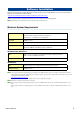
Software Installation Begin by downloading the DME Designer Combo Installer and the USB-MIDI Driver from the “Downloads” page on the Yamaha Pro Audio website (http://www.yamahaproaudio.com/downloads/firm_soft/index.html). Select and download the appropriate driver for your computer’s operating system. n DME Designer V4.0 supports Windows7, Windows Vista, and Windows XP.
Software Installation Download the DME Designer Combo Installer Use this link to download the required software. n The DME-N Network Driver can be downloaded individually, but the DME Designer Combo Installer allows you to download and install both DME Designer and the DME-N Network Driver in one operation. DME Designer: DME system settings can be made using this dedicated application. n DME designer can be used in online mode even if a DME unit is not connected.
Software Installation Install DME Designer and DME-N Network Driver Follow the procedure outlined below to install the DME Designer application and the DME-N Network Driver using the DME Designer Combo Installer. 1 After the downloaded compressed file is properly extracted, double-click the “setup.exe” file. The setup wizard for the DME Designer Combo Installer will be displayed.
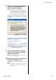
Software Installation 8 When the “Welcome to the InstalShield Wizard for Yamaha USB-MIDI Driver” window appears, click [Next]. n When the number of installed USB-MIDI drivers exceeds the Windows OS limit (10 instances) an error message will appear. In this case reinstall the Yamaha USB-MIDI Driver after uninstalling any unnecessary USB-MIDI drivers (page 28). If the warning message below appears during the installation, click [Yes], [Continue Anyway], or [Install].
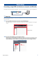
Basic Setup Connecting a single DME unit directly to a computer via USB cable This section covers the most basic configuration – that is, using a single computer to control a single DME unit. USB cable 1 Preparation Before launching DME Designer, it is critical that the DME unit is turned on and then connected to the computer using a USB cable. 1-1 Once the DME unit has been connected, launch DME Designer.
Basic Setup In response to this action, the Device Group and Sampling Frequency Settings window will be displayed. Click the [OK] button to proceed. n Group settings are not necessary when only one DME unit is connected. The sampling rate can be changed later on. 2 Mini-YGDAI Card Settings (DME64N/24N only) The following settings are used only when one or more Mini-YGDAI cards are installed in a DME24N or DME64N. If this is not the case, proceed to Step (3. Component Layout and Connection) below.
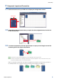
Basic Setup 3 Component Layout and Connection 3-1 Double-click the icon for your DME unit to display the Configuration window. Double-click 3-2 Drag and drop the components that you require into the configuration area from the list on the left-hand side. Drag and drop 3-3 To connect components, click the required input or output port and drag the end of the connecting wire to the required destination. n Components can also be freely dragged around the configuration area using the mouse.
Basic Setup 4 Creating scenes 5 Going On-Line In order to transmit all data created thus far to a DME unit, it is necessary to store at least one scene. The scene store procedure is outlined below. When synchronization with the DME unit has been achieved and the connection is online, the DME Designer settings are written to the DME unit. 4-1 5-1 4-2 Click the [Scene Manager] button from the Main Panel window to display the “Scene Manager” dialog box.
Basic Setup 5-4 When the Synchronization window is displayed, the text “Select IP Address” will be displayed in red. Click this message and select the required IP address from the drop-down menu. 5-8 n If the correct IP address is not displayed, check that the DME unit is properly connected to the computer. 5-9 When writing has been completed, the message, “Saving the Designer file after synchronization will enhance the speed of the next synchronization. Do you want to save now?” will be displayed.
Basic Setup 6 Checking sound output In the case of DME24N, DME8i-C, DME4io-C, DME8i-ES or DME4io-ES units, appropriate HA control settings must be made prior to checking the system’s sound output. 6-1 Right-click the [Analog Input] component and select [Open HA Editor] from the drop-down menu. An “Analog” dialog box that allows head amp settings will appear. By default, the gain is set to +10 dBu (i.e., the lowest possible gain).
Advanced Setup Connecting multiple DME units to a computer via Ethernet cables In the following two cases, a USB cable should not be used to connect your computer and DME units for actual operation; instead, you should make the necessary connections via Ethernet cables. • Two or more DME units are to be controlled in a single device group (using a Network switch).
Advanced Setup DME Network Settings Before making the DME network connections, set the device group and IP address for each DME unit from DME Designer via a USB connection. By default, all DME units are assigned the IP address 192.168.000.002. Please ensure that the USB-MIDI driver has been installed before proceeding. n The same driver can be used for multiple DME units of the same type (DME64N, DME24N, DME Satellite).
Advanced Setup 5 Make sure that the “Network Setup” dialog box settings are made as shown below, the click the [OK] button. Master/Slave Master IP Address 192.168.0.2 Master ID – Link Mode 100Base-TX Group master settings (DME4io-C in the example). n The default settings can be used for the group master. 6 Use the same procedure to set the slave (DME8o-C and DME64N in the example) settings and IP address. DME8o-C Master/Slave IP Address DME64N Slave 192.168.0.3 192.168.0.4 Master ID 192.
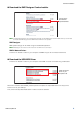
Advanced Setup Computer Network Settings The computer’s IP address and TCP/IP filtering must be set up to allow network communication with the DME device(s). Windows Vista / Windows 7 1 6 Select [Start] [Control Panel], then click or double-click [Network and Sharing Center] or [View network status and tasks].
Advanced Setup 4 Click [Properties] on the [General] tab. The “Local Area Connection Properties” dialog box will be displayed. 5 Select [Internet Protocol (TCP/IP)] on the [General] tab, then click [Properties]. The “Internet Protocol (TCP/IP) Properties” dialog box will be displayed. 6 9 Enter your computer’s IP address into [IP address], the Gateway’s IP address into [Default gateway], and “255.255.255.0” into [Subnet mask].
Advanced Setup Setting the DME-N Network Driver In order for the computer to recognize the DME device(s), it is necessary to register the IP address and device name of the DME device that is the Device Group Master. n Refer to page 23 for details on DME-N Network Driver setup. 1 Select [Start] [Control Panel]. The “Control Panel” will appear.
Advanced Setup 7 Device Name Select the DME unit that is to function as the Device Group Master from the Target Device List, enter the Device Name and Device Port No., and click the [Apply] button. Displayed as the port name in DME Designer. Device Port No. (MIDI port number) Set to “1.” “2” is also available for DME64N/24N devices. 8 Click the [Save and Close] button to close the dialog box.
In-depth Information on DME Units Connecting to External Controllers ICP1, CP4SF, CP1SF, and CP4SW controllers are available as optional extras for remote external control of the DME units. For details regarding installation of a control panel and connection to the DME unit, please refer to the owner’s manual that came with the control panel.
In-depth Information on DME Units Setting up DME64N/24N Networks via Panel Operations Device group and IP address settings for DME64N and DME24N units can be made directly via their front panels as follows. 1 2 Turn on the DME64N/24N. IP Address Set the IP addresses of the DME devices. All DME devices in the same Device Group must be set to the same network address. Press the [HOME] button to display the main screen.
In-depth Information on DME Units Related web site on DME series and peripherals The latest information about DME units is available from the Yamaha Pro Audio website: http://www.yamahaproaudio.com The latest version of the DME unit firmware and DME Designer can be downloaded from the Yamaha ProAudio website: http://www.yamahaproaudio.com/downloads/firm_soft/index.
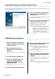
DME-N Network Driver Setup Details “DME-N Network Driver” dialog box Select [Start] [Control Panel] [DME-N Network Driver] to open the “DME-N Network Driver” dialog box. The parameters in this dialog box set up the device information of the DME on the network. [Remove] Button Deletes the selected device from the list.
DME-N Network Driver Setup Details [Device Port No.] The MIDI port number of the device selected in the Target Device List can be set via this menu. The MIDI port number also functions as device ID number. It can be set to “1” or “2” for DME64N/24N units. It should be set to “1” for DME Satellite units. n The MIDI port number must be set properly or communication with the device will not be possible.
DME-N Network Driver Setup Details “Advanced Settings” dialog box Click [Advanced Settings] in the DME-N Network Driver dialog box to display the Advanced Settings dialog box. The parameters presented in this dialog box are used to setup automatic detection by the DME-N Network Driver; furthermore, setup files can also be imported and exported here.
Troubleshooting & Tips Problem The DME unit does not operate correctly in response to control from DME Designer via USB. Possible cause Corrective action DME Designer was launched before connecting the USB cable and turning on the DME unit. Ensure that the USB cable is connected and the DME unit is turned on before launching DME Designer. The USB-MIDI Driver Thru ON/OFF parameter is not set to “OFF”. The USB-MIDI Driver Thru ON/OFF parameter is not set to “OFF”.
Troubleshooting & Tips Problem Possible cause Corrective action The message “Reset Config…” is displayed for a long time in the message area of the Synchronization window. Processing may take time when many scenes have been stored. – The monitor output cannot be set. (Applies to the DME64N and DME24N only.) Output ports that are already in use (i.e. wired) cannot be selected as monitor outputs. Select an unused output port.
Troubleshooting & Tips Uninstall the USB-MIDI Driver Windows XP Windows Vista / Windows 7 1 1 2 Disconnect all USB devices from the computer except for the mouse and keyboard. Start the computer and log on to the Administrator account. 2 Exit from any open applications and close all open windows.