
User Manual


5
Notes for DME64N/DME24N Version 1.2
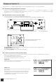
2. Setting the Monitoring Point from DME Designer (Probe Monitor Function)
For details, see the “DME Designer Version 1.2 Owner’s Manual.”
When you use the probe monitor function, the monitoring point switches and the [MONITOR] indicator lights up.
At the same time, the “Probe” mark appears on the DME64N/24N display, and the monitoring point selected in the DME64N/
24N is disabled.
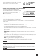
3. Monitoring OFF
You can turn OFF the monitoring function at the DME unit.
This turns OFF output of sound from the [PHONES] terminal and the Monitor OUT set in DME Designer.
Method of Operation
When the monitoring function is set to ON ([MONITOR] indicator lit steadily or blinking), you can turn it OFF by pressing
the [MONITOR] button.
The [MONITOR] indicator light turns OFF.
When you want to turn ON the monitoring function, select a monitoring point.
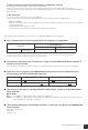
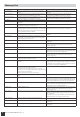
The following notes supplement the information in the DME64N/DME24N Owner’s Manual:
■
Only a limited number of some components can be arranged in a configuration.
(*1)
• Input components (Slot In, Cascade In) and output components (Slot Out, Cascade Out) cannot be directly connected.
• Components other than input/output components cannot be arranged.
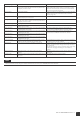
■
The following notes apply when “Preparation” on page 19 of the DME64N/24N Owner’s Manual is
started up for the first time.
The meter does not operate during the first startup. The [SIGNAL][PEAK] indicators also do not work in the DME24N.
■
There is an error on page 29 of the DME64N/24N Owner’s Manual, where it states that there is
current between the OUT and GND [GPI] terminals.
■
The following notes apply to “Net Page (Network Settings Page)” on page 47 of the DME64N/24N
Owner’s Manual:
3
Link Mode
Error:
The 100Base-Tx: [NETWORK] terminal operates as 100Base-TX.
Correct:
The 100Base-Tx: [NETWORK] terminal operates as 100Base-TX if possible. If the network environment does not
support 100Base-TX, it operates as 10Base-T.
■
The following notes apply to the RS-232C terminal in “Control I/O)” on page 63 of the DME64N/24N
Owner’s Manual:
Baud Rate = 38,400 bps
Data = 8bit
Stop bit = 1bit
Component
Maximum number of components that can be arranged
(for each DME unit)
DME64N DME24N
Matrix Mixer 64 Input 32 Output
64 Input 64 Output
1 (*1) 0 (Cannot be arranged)
Incorrect Correct
Illustration note Max. 6mA Max. 16mA
Caution sentence Make sure that the current between the OUT and
GND [GPI] connectors is less than 6mA
.
Make sure that the current between the OUT and
GND [GPI] connectors is less than 16mA.