DIGITAL MIXING ENGINE SATELLITE Owner’s Manual EN
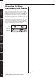
Precautions for Using a Rack-mounted DME Satellite If several DME Satellite units (or a DME Satellite unit together with other devices) are installed in a poorly-ventilated rack, the heat generated by each unit may raise the temperature inside the rack, preventing the DME Satellite from performing as designed. When mounting DME Satellite units in a rack, please leave one rack space vacant for every two units.
Explanation of Graphical Symbols The lightning flash with arrowhead symbol within an equilateral triangle is intended to alert the user to the presence of uninsulated “dangerous voltage” within the product’s enclosure that may be of sufficient magnitude to constitute a risk of electric shock to persons.
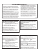
FCC INFORMATION (U.S.A.) 1. IMPORTANT NOTICE: DO NOT MODIFY THIS UNIT! This product, when installed as indicated in the instructions contained in this manual, meets FCC requirements. Modifications not expressly approved by Yamaha may void your authority, granted by the FCC, to use the product. 2. IMPORTANT: When connecting this product to accessories and/ or another product use only high quality shielded cables. Cable/s supplied with this product MUST be used. Follow all installation instructions.
PRECAUTIONS PLEASE READ CAREFULLY BEFORE PROCEEDING * Please keep this manual in a safe place for future reference. WARNING Always follow the basic precautions listed below to avoid the possibility of serious injury or even death from electrical shock, short-circuiting, damages, fire or other hazards. These precautions include, but are not limited to, the following: Power supply/Power cord Water warning • Only use the voltage specified as correct for the device.
Handling caution Backup battery • Do not use the device for a long period of time at a high or uncomfortable volume level, since this can cause permanent hearing loss. If you experience any hearing loss or ringing in the ears, consult a physician. • Do not rest your weight on the device or place heavy objects on it, and avoid use excessive force on the buttons, switches or connectors. • This device has a built-in backup battery.
Foreword Contents Introduction to the DME Satellite Foreword .......................................... 7 Connecting to an External Device............. 29 Accessories (Please make sure the following items are included in the package.)................................................. Options........................................................................... About the Product Names............................................... About the Firmware Version ..........................................
Foreword Thank you for choosing a Yamaha DME8i-C/DME8o-C/DME4io-C Digital Mixing Engine Satellite. In order to take full advantage of the features and performance provided by the DME8i-C/DME8o-C/DME4io-C, we urge you to read this owner’s manual thoroughly before connecting or using the unit. Keep this manual in a safe place for future reference.
Foreword Foreword Precautions for Using a Rack-mounted DME Satellite Introduction to the DME Satellite Controls and Connectors If you install the DME Satellite along with other DME Satellite units or other devices in a poorly ventilated rack, the ambient temperature inside the rack may rise, resulting in inefficient performance. Be sure to install the DME Satellite in a well-ventilated rack and make sure that the heat will be ventilated efficiently.
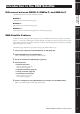
Foreword Introduction to the DME Satellite Differences between DME8i-C, DME8o-C, and DME4io-C Introduction to the DME Satellite The differences between these three models are as follows: ■ DME8i-C This model features 8-channel analog inputs. ■ DME8o-C This model features 4-channel analog inputs and 4-channel analog outputs. DME Satellite Features In addition to basic mixing and matrix output functions, the DME Satellite includes a equalizers, compressors, delay, etc.
Foreword Introduction to the DME Satellite Audio System Network Introduction to the DME Satellite Multiple DME series units that are interconnected in a network via Ethernet function as a single audio system. In a DME audio system, a group of the same models that can be operated in sync is called a “device group;” audio processing divisions that accommodate multiple device groups are called “zones;” and the entire area serviced by the acoustic system is called an “area.
Foreword Introduction to the DME Satellite Scene structure Scene Preset Parameter Configuration Matrix Mixer Scene 1 Ex.: Gate • Attack • Decay • Range • Threshold • Key in • Hold Scene 2 16 x 8 Scene 999 Component Controls and Connectors A combination of all configuration and preset parameters is called a “scene.” Scenes can be recalled from an ICP1, GPI device, other external controllers, or computer. Up to 999 scenes can be stored for each device group.
Foreword Introduction to the DME Satellite Signal Types DME Satellite audio system signals can be broadly categorized as follows. Introduction to the DME Satellite 1 Audio The DME Satellite will be required to send and receive audio signals to and from other DME series units as well as other audio equipment. Audio signal transmission and reception will occur primarily via the [INPUT] and [OUTPUT] connectors. The CobraNet connectors can also transmit and receive digital audio signals.
Foreword Introduction to the DME Satellite System Examples Space B Space A DME8i-C Computer ICP1 INPUT USB PEAK PEAK PEAK SIGNAL SIGNAL SIGNAL PEAK PEAK PEAK SIGNAL SIGNAL SIGNAL DIGITAL MIXING ENGINE SATELLITE INPUT Analog In DME8i-C Introduction to the DME Satellite Multiple DME Satellite units: Large-scale system INPUT USB PEAK PEAK PEAK SIGNAL SIGNAL SIGNAL PEAK PEAK PEAK SIGNAL SIGNAL SIGNAL DIGITAL MIXING ENGINE SATELLITE INPUT Analog In DME8i-C INPUT USB PEAK
Foreword Introduction to the DME Satellite About DME Designer Introduction to the DME Satellite Controls and Connectors DME Designer software enables you to integrate, configure, and control the DME series system from a connected computer. You can build the DME series audio system using graphic blocks in DME Designer that are displayed on the computer monitor.
Foreword Introduction to the DME Satellite About CobraNet Controls and Connectors Developed by Cirrus Logic, Inc., U.S., CobraNet technology allows real-time uncompressed digital audio distribution over industry-standard Fast Ethernet (100 megabits/sec.) networks. Up to 128 channels, 64 in each direction, can be carried simultaneously over a CobraNet network. (The number of channels available depends on the performance of the devices and the condition of audio signals.
Foreword Introduction to the DME Satellite Multicast and unicast bundles Introduction to the DME Satellite Controls and Connectors CobraNet bundles can be either multicast or unicast. Multicast bundles are transmitted from one device to multiple devices on the network (one-to-many). Unicast bundles are transmitted from one device to another (one-to-one). Unicast bundles are transmitted only when another device is configured to receive them by assigning the same bundle numbers.
Foreword Introduction to the DME Satellite NO T E Controls and Connectors One device on the CobraNet network works as the conductor (network sync master). All other CobraNet devices are performers (network sync slaves). Each device synchronizes its own internal clock to the beat packets (sync signals) transmitted by the conductor. The conductor device is chosen automatically and no user intervention is required.
Foreword Controls and Connectors Front Panel Introduction to the DME Satellite 2 5 DME8i-C 7 9 INPUT USB PEAK PEAK PEAK SIGNAL SIGNAL SIGNAL PEAK PEAK PEAK SIGNAL SIGNAL SIGNAL DIGITAL MIXING ENGINE SATELLITE INPUT 1 34 6 8 Controls and Connectors 2 5 DME8o-C USB Connecting to a Computer 1 34 6 7 PEAK PEAK PEAK SIGNAL SIGNAL SIGNAL PEAK PEAK PEAK SIGNAL SIGNAL SIGNAL 9 DIGITAL MIXING ENGINE SATELLITE 8 2 5 7 9 DME4io-C INPUT USB Audio I/O Connection 1 Con
Foreword Controls and Connectors Introduction to the DME Satellite 4 [ERROR] Indicator Lights when an error occurs. The [PEAK] indicators reflect the type of error. The [ERROR] indicator flashes when the battery charge is getting low. Controls and Connectors 5 [IN USE/CONDUCTOR] Indicator Lights orange when the power is supplied correctly to the DME Satellite. It flashes while the device is operating as a CobraNet conductor.
Foreword Controls and Connectors Rear Panel Introduction to the DME Satellite DME8i-C 1 3 4 5 6 7 9 MAC ADD * XX XX XX XX XX XX * RS-232C RS-422 8 2 Controls and Connectors DME8o-C 1 3 4 5 6 7 MAC ADD * XX XX XX XX XX XX * RS-232C RS-422 Connecting to a Computer 2 DME4io-C ) 8 1 3 4 5 6 7 9 MAC ADD * XX XX XX XX XX XX * RS-232C Audio I/O Connection RS-422 2 Connecting to an External Device 1 [AC IN] Connector Connect to the AC mains using the supplied AC power cord
Foreword Controls and Connectors Controls and Connectors Introduction to the DME Satellite 6 CobraNet [PRIMARY]/[SECONDARY] Connectors The DME Satellite features two CobraNet connectors for built-in redundancy: one for a primary network connection, another for a secondary or backup connection. If for some reason the primary connection fails (e.g., a cable is damaged, inadvertently disconnected, or a switching hub fails), the secondary connection automatically kicks in.
Foreword Connecting to a Computer USB Connection Introduction to the DME Satellite To connect multiple DME Satellite units to a network, you must assign appropriate IP addresses and make other network settings on all units. To achieve this, you need to connect the [USB] connector of one of the DME Satellite units to the USB port of the computer using USB cables, install USB-MIDI Driver and DME Designer on the computer, then assign the IP addresses to the DME Satellite units from DME Designer.
Foreword Connecting to a Computer Network Settings Setting the IP address Host Address Each group of digits between periods in an IP address is called an “octet.” These groups of digits are called “1st octet,” “2nd octet,” etc., starting from the left-most digit group. You cannot specify 0, 127, or 223 through 255 for the 1st octet of the network address. You can specify the following range of values for the 4th octet.
Foreword Connecting to a Computer Ethernet Connection ([NETWORK] Connector) To control the DME Satellite from the computer via Ethernet, use an Ethernet cable to connect the [NETWORK] connector on the rear panel of the DME Satellite to the computer, then install DME-N Network Driver. Introduction to the DME Satellite N OT E • Refer to the separate DME Designer Installation Guide for details on installing DME-N Network Driver.
Foreword Connecting to a Computer Control from a computer in the same subnet group Device Group Introduction to the DME Satellite Group Master INPUT USB PEAK PEAK PEAK SIGNAL SIGNAL SIGNAL PEAK PEAK PEAK SIGNAL SIGNAL SIGNAL DIGITAL MIXING ENGINE SATELLITE INPUT DME Satellite (IP address: 192.168.0.7) Ethernet Cable Ethernet Straight Cable Ethernet Straight Cable Computer (IP address: 192.168.0.
Foreword Connecting to a Computer Connecting multiple device groups Device Group 1 Device Group 2 Introduction to the DME Satellite Group Master Group Master INPUT USB INPUT PEAK PEAK PEAK SIGNAL SIGNAL SIGNAL DIGITAL MIXING ENGINE SATELLITE USB PEAK PEAK SIGNAL SIGNAL PEAK PEAK PEAK PEAK PEAK SIGNAL SIGNAL SIGNAL SIGNAL SIGNAL INPUT DIGITAL MIXING ENGINE SATELLITE INPUT DME Satellite (IP address: 192.168.0.2) Ethernet Cable DME Satellite (IP address: 192.168.0.
Foreword Audio I/O Connection The DME Satellite CobraNet connectors enable you to transfer digital audio, control, and word clock signals. Refer to page 15 for more information on CobraNet. Connecting and setting up the DME Satellite in accordance with other CobraNet compatible equipment allows for broad-ranging audio and word clock signal networkability. Refer to the MY16-C or MY16-CII Owner’s Manual for more information on the corresponding interface card.
Foreword Audio I/O Connection Analog Audio Connection ([INPUT] & [OUTPUT] Connectors) Introduction to the DME Satellite The DME Satellite can directly input and output audio signals via the [INPUT] and [OUTPUT] connectors. Wire the supplied Euroblock plugs (3P) as shown below. You can use DME Designer to set the head amplifier gain and turn the phantom power on and off for each [INPUT] connector. Cable preparation Prepare cables to be attached to a Euroblock plug as shown below.
Foreword Connecting to an External Device Controlling external head amplifiers from the DME Satellite Connecting to a Computer You can remotely control the AD8HR or AD824 head amplifier settings from DME Designer. Up to eight AD8HR/AD824 head amplifiers can be connected. Be sure to set the dip switch on the rear panel of the DME Satellite to “RS-422” (page 20) when connecting to AD8HR or AD824 remote head amplifiers.
Foreword Connecting to an External Device CobraNet Connection (CobraNet Connectors) Introduction to the DME Satellite If you install an MY16-C or MY16-CII interface card on a PM5D Digital Mixing Consol and connect it to the DME Satellite via the CobraNet connectors, you can remotely control the DME Satellite from the PM5D, as well as transfer audio and word clock signals between them. Refer to the PM5D/PM5D-RH Owner’s Manual for more information on the PM5D’s DME Control function.
Foreword Connecting to an External Device • For more information on the CP4SW, CP4SF, and CP1SF Control Panels, refer to the CP4SW/CP4SF/ CP1SF Owner’s Manual. • You can use DME Designer to set up the system so that scene recall operations and User Defined parameter control can be carried out from connected GPI control devices. Refer to the DME Designer Owner’s Manual for details.
Foreword Other Functions Initializing the DME Satellite Introduction to the DME Satellite You can initialize the DME Satellite internal memory. Select one of the following initialization types: Initialize DME: All scenes and preset parameter settings, excluding components, WAVE files, and files saved via the File Storage function will be deleted. The Utility settings will be set to default values.
Foreword References ICP1 CONTROL PANEL CP4SW 10 10 10 10 10 0 0 0 0 0 CONTROL PANEL CONTROL PANEL CP4SF CP1SF DME8i-C/DME8o-C/DME4io-C Owner’s Manual Other Functions These controllers connect to DME series units via the [GPI] connectors. These controllers control only the DME series units to which they are directly connected. The controller switches enable you to turn the parameter settings On and Off. The switch LEDs enable you to check the parameter status.
Foreword References Troubleshooting Introduction to the DME Satellite Controls and Connectors Connecting to a Computer Audio I/O Connection Connecting to an External Device The device does not turn on, or the panel LEDs do not light up. • Connect the power cord properly (page 7). • Make sure that the [POWER] switch is turned ON (page 19). • If the device still does not turn on, contact a Yamaha dealer. No communication between the DME Satellite and the DME Designer application software.
Foreword References MIDI Data Format MIDI Control Change and Parameter Change messages transmitted to the DME8i-C/DME8o-C/DME4io-C can be used to control parameters according to the “MIDI Control Change Table” and “MIDI Parameter Change Table” assignments.
Foreword References Bank Select MSB 4. MIDI Format Number Format Notation Introduction to the DME Satellite Numbers ending with “h” are in hexadecimal format, while numbers ending with “b” are binary format. Characters “A” through “F” in hexadecimal numbers represent decimal values 10 through 15. Other lower-case characters (usually “n” or “x”) can represent any number.
Foreword aah Parameter ddh Data Value ddh ddh ddh ddh EOX F7h (0aaaaaaab) (0dddddddb) Parameter Address Low data 0 (0dddddddb) (0dddddddb) (0dddddddb) (0dddddddb) (11110111b) data 1 data 2 data 3 data 4 End of Exclusive Supplementary Information 2 Setting the Parameter Change Message Parameter Data Values The Parameter change parameter values are expressed as 32-bit integers with or without parity. • A parity bit (positive:0, negative:1) is added above the most significant value bit (bit 31).
Foreword MIDI Implementation Chart YAMAHA [Digital Mixing Engine Satellite] Model DME8i-C, DME8o-C, DME4io-C MIDI Implementation Chart Function...
Foreword References Display Messages Flashing Lit PEAK PEAK PEAK SIGNAL SIGNAL SIGNAL PEAK PEAK PEAK SIGNAL SIGNAL SIGNAL Flashing Lit PEAK PEAK PEAK SIGNAL SIGNAL SIGNAL PEAK PEAK PEAK SIGNAL SIGNAL SIGNAL Flashing Lit PEAK PEAK PEAK SIGNAL SIGNAL SIGNAL PEAK PEAK PEAK SIGNAL SIGNAL SIGNAL Flashing Lit Lit PEAK PEAK PEAK SIGNAL SIGNAL SIGNAL PEAK PEAK PEAK SIGNAL SIGNAL SIGNAL PEAK PEAK PEAK SIGNAL SIGNAL SIGNAL PEAK PEAK PEAK SIGNAL SIGNAL
Foreword References General Specifications Sampling Frequency Introduction to the DME Satellite Normal Rate:48kHz Double Rate:96kHz (±37ppm for conductor) (±50ppm for performer) Maximum Voltage Gain Miscellaneous Gain: –60dB, RL:600Ω, 64dB INPUT to OUTPUT Power Consumption 40W Dimensions (HxDxW) 44x361x480 mm Net Weight 4.
Foreword References Output RL INPUT 1–4 OUTPUT 1–4 600Ω Total Harmonic Distortion CONDITIONS MIN TYP MAX UNITS input level: –60dBu, GAIN: –60dB +2.0 +4.0 +6.0 dBu input level: +10dBu, GAIN: +10dB +2.0 +4.0 +6.0 dBu MIN TYP MAX UNITS +4dB@20Hz–20kHz, 20Hz–40kHz (fs=96kHz), GAIN: –60dB 0.1 % +4dB@20Hz–20kHz, 20Hz–40kHz (fs=96kHz), GAIN: +10dB 0.05 % +22dB@1kHz, GAIN: +10dB 0.
Foreword References Input Output RL CONDITIONS MIN Introduction to the DME Satellite Rs=150Ω, GAIN: –60dB All input & output level controls: 0dB INPUT 1–4 OUTPUT 1–4 600Ω TYP MAX UNITS –128 EIN EIN –127 dBu –64 Rs=150Ω, GAIN: +10dB All input & output level controls: 0dB –82 dBu –79 dBu * Hum & Noise are measured with a 6dB/octave filter @12.7kHz; equivalent to a 20kHz filter with infinite dB/octave attenuation.
Foreword References MIN TYP MAX UNITS INPUT 1–4 OUTPUT 1–4 PEAK red LED:ON –3 dBFs SIGNAL green LED:ON –40 dBFs PARAMETER CONDITIONS Signal Delay MIN CobraNET Latency: 5.33msec ANALOG INPUT to ANALOG OUTPUT@96KHz CobraNET Latency: 2.67msec CobraNET Latency: 1.33msec TYP MAX UNITS 6.12 msec 3.45 msec 2.
Foreword References CONTROL I/O CHARACTERISTICS Terminal Introduction to the DME Satellite Format Level Connector IN – 0–5V EUROBLOCK *1 (3.5mm pitch) OUT – TTL +V – 5V Ethernet IEEE802.3 10Base-T/100Base-TX RJ-45 USB USB 1.1 Function – Type B REMOTE RS-232C/RS-422 RS-232C/RS-422 D-SUB 9P (Male) GPI Controls and Connectors *1 Inputs: 8 channels, Outputs: 4 channels Inputs: Not apply 2 wire Fader mode Outputs: Imax/pin = 16mA Outputs: VH = 2.5V(min.), VL = 0.6V(max.
Foreword References Controls and Connectors Rubber feet are included in the package. Unit: mm * Specifications and descriptions in this owner’s manual are for information purpose only. Yamaha Corp. reserves the right to charge or modify products or specifications at any time without prior notice. Since specifications, equipment or options may not be the same in every locale, please check with your Yamaha dealer.
Foreword References Index Introduction to the DME Satellite A I About DME Designer ............................................................. 14 ICP1 ........................................................................................33 [AC IN] Connector ................................................................. 20 [IN USE/CONDUCTOR] Indicator ......................................19 Analog Audio Connection ....................................................... 28 Initialize DME ...
Foreword References secondary (backup) .................................................................. 19 Setting the IP address .............................................................. 23 [SIGNAL] Indicators .............................................................. 19 Introduction to the DME Satellite Signal Types ............................................................................ 12 Straight and Crossover Cable Wiring ...................................... 44 System Examples ....
Foreword Introduction to the DME Satellite Controls and Connectors Connecting to a Computer Audio I/O Connection Connecting to an External Device Other Functions References DME8i-C/DME8o-C/DME4io-C Owner’s Manual 48 MEMO
References Other Functions Connecting to an External Device Audio I/O Connection Connecting to a Computer Controls and Connectors Introduction to the DME Satellite Foreword MEMO DME8i-C/DME8o-C/DME4io-C Owner’s Manual 49
Foreword Introduction to the DME Satellite Controls and Connectors Connecting to a Computer Audio I/O Connection Connecting to an External Device Other Functions References DME8i-C/DME8o-C/DME4io-C Owner’s Manual 50 MEMO
For details of products, please contact your nearest Yamaha representative or the authorized distributor listed below. Pour plus de détails sur les produits, veuillez-vous adresser à Yamaha ou au distributeur le plus proche de vous figurant dans la liste suivante. NORTH AMERICA CANADA Yamaha Canada Music Ltd. 135 Milner Avenue, Scarborough, Ontario, M1S 3R1, Canada Tel: 416-298-1311 U.S.A. Yamaha Corporation of America 6600 Orangethorpe Ave., Buena Park, Calif. 90620, U.S.A.
Yamaha Pro Audio global web site: http://www.yamahaproaudio.com/ Yamaha Manual Library http://www.yamaha.co.jp/manual/ This document is printed on chlorine free (ECF) paper with soy ink. U.R.G., Pro Audio & Digital Musical Instrument Division, Yamaha Corporation © 2006 Yamaha Corporation WG50630 606IPDHxx.