UCA DPX–1 Digital Cinema Projector Projecteur Cinema Numerique OWNER’S MANUAL MODE D’EMPLOI
IMPORTANT SAFETY INSTRUCTIONS 1 Read these instructions. CAUTION RISK OF ELECTRIC SHOCK DO NOT OPEN 2 Keep these instructions. 3 Heed all warnings. 4 Follow all instructions. CAUTION: TO REDUCE THE RISK OF ELECTRIC SHOCK, DO NOT REMOVE COVER (OR BACK). NO USER-SERVICEABLE PARTS INSIDE. REFER SERVICING TO QUALIFIED SERVICE PERSONNEL. • Explanation of Graphical Symbols 5 Do not use this apparatus near water. 6 Clean only with dry cloth. 7 Do not block any ventilation openings.
FCC INFORMATION (for US customers only) 1. IMPORTANT NOTICE: DO NOT MODIFY THIS UNIT! This product, when installed as indicated in the instructions contained in this manual, meets FCC requirements. Modifications not expressly approved by Yamaha may void your authority, granted by the FCC, to use the product. 2. IMPORTANT: When connecting this product to accessories and/or another product use only high quality shielded cables. Cable/s supplied with this product MUST be used.
Caution: Read this before operating this unit. • To assure the finest performance, please read this manual carefully. Keep it in a safe place for future reference. • When not planning to use this unit for a long period of time (i.e. vacation), disconnect the AC power plug from the wall outlet. Installation • When disconnecting the power cord from the wall outlet, grasp the plug; do not pull the cord.
Inappropriate places for installation If this unit is not correctly installed in an appropriate place, it may cause fire or failure, or damage to this unit may result. Carefully choose the place to install this unit by avoiding the places listed below. 1. Places where the temperature and humidity vary greatly • Do not install this unit in a place where the temperature and humidity become extremely high or the temperature becomes extremely low. • This unit must be used within a temperature range of 5—35°C.
Memo III
PRECAUTIONS ENGLISH Thank you for purchasing this YAMAHA product. We hope it will give you many years of trouble-free enjoyment. For the best performance, read this manual carefully. It will guide you in operating your YAMAHA product. Features • Wide variety of input terminals to support the latest video formats • 0.
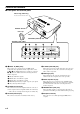
Controls and functions ■ Front panel and terminal panel Focus ring, zoom ring Focuses and zooms the lens Remote sensor Lens cap Lens Ventilation (exhaust) slot Terminal panel 8 9 0 q w RGB/YPBPR/YCBCR S VIDEO VIDEO INPUT B TRIGGER OUT INPUT A G/Y B/PB/CB 1 R/PR/CR 2 4 1—5 INPUT A (BNC jacks) These jacks receive component video and RGB signals. Component video signals from an A/V component are sent to the 1—3 jacks. RGB signals from a computer are sent to the 1—5 jacks.
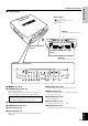
■ Control panel Power switch C IN E M A P R O J E C T O R D P X –1 Primary power switch. “ ” turns on and sets this unit in the standby mode. “ ” turns off this unit. INTRODUCTION Controls and functions D IG IT A L AC inlet To plug in the supplied power cord.
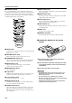
Controls and functions ■ Remote control 0 INPUT button (P.11) The corresponding buttons on the control panel and the remote control perform same functions. Use the remote control by aiming at the remote control sensor located on the front or back of this unit. The operation range is 50 degrees horizontally and 30 degrees vertically within a distance of 6 m (20 feet). 1 2 5 6 q RESET button (P.18) Resets the parameter to its factory setting when pressed while adjusting the parameter on the menu.
INSTALLATION How to install There are four ways this unit can be installed: installing on a tabletop in front of the screen, mounting on the ceiling in front of the screen, installing on a tabletop behind a semi-translucent screen, mounting on the ceiling behind a semi-translucent screen. It is necessary to set the installation method for “INSTALLATION” in the menu group 4 on the menu described later. (See page 17.
How to install ■ Screen setting 4:3 screen The screen height depends on your screen size. This unit projects facing slightly upward, although projecting symmetrically about the lens center on the horizontal axis. The following charts show the height [H] from the lens center to the screen bottom. Consider dimension [H] when determining the position to set your screen.
How to install ■ Installation methods 1. Installing on a tabletop Projection distance [L] See page 5. Screen [H] See page 6. INSTALLATION This unit projects images when set on a tabletop with a certain height in front of the screen. The table height and [H] described on page 6 must be determined first to decide on how high the screen should be set for the best result. The height from this unit’s bottom to the lens center is 8 cm (3-1/8 inch).
CONNECTION How to connect • Before making connections, make sure that the power of this unit and other components is turned off. • Some components require different connection methods and have different jack names. Refer to the operation instructions for each component to be connected to this unit. • Plug in this unit correctly to prevent from creating noise or troubles.
How to connect ■ Connecting a computer There are three types of terminals to connect this unit to a computer as listed below. Use the correct cables for the terminals to be connected.
BASIC OPERATION Using this unit This section describes the basic projecting operation after installation and connection have been completed. Detailed settings must be made for installation, screen, input signal and so on, by following the menu setting procedure described in the section starting on page 15. ■ Focusing Press the PATTERN button to project the stored test pattern. Adjust the lens so that it comes into focus by rotating the focus ring. The image size can be also adjusted with the zoom ring.
Using this unit ■ Selecting the input source ◆ Notes ◆ Press the INPUT button to display the menu for input signals on the screen. Select the input terminal and the input signal to be projected by pressing the h or g button, and confirm the selection by pressing the SELECT button. • When an ordinary video signal or an interlaced video signal of a 24frame/second film is input, the interlace/progressive (i/p) conversion circuit built into this unit automatically identifies the type of signals.
Using this unit ■ Selecting “ASPECT” “ASPECT” selects the most appropriate way of displaying the image on the screen for the six common types of signals listed below. Available parameters for “ASPECT” change depending on the “SCREEN ASPECT” setting. This unit has the “AUTO” mode which automatically detects the type of signals and changes the display aspect. This mode is effective when information about the signal type is included in the signal. Press the ASPECT button for the desired display aspect.
Using this unit ● Available aspect modes when “SCREEN ASPECT” is set to “16:9” 1 AUTO [Examples] When the input signal is in letterbox or squeeze, this mode detects it and automatically switches to the most appropriate mode. This mode is effective only when the signal is sent with information about its type. 2 NORMAL This mode projects the image vertically in full on the screen without cutting any input signal. 3 SQUEEZE This mode desqueezes the video which has been recorded as horizontally squeezed.
Using this unit ■ Turning off this unit ■ Indicators 1. When you have finished using this unit, press the There are four indicators on this unit to display the operating status of this unit. STANDBY/ON button. There will be a message to confirm turning off this unit. Press the STANDBY/ON button again to turn off this unit. The lamp turns off and the indicator flashes in orange while the fan is rotating to cool the lamp for approximately two minutes.
MENU Menu structure It is necessary to make various settings on the menu so that this unit can achieve the best performance. The menu has a three-level hierarchy; menu group, menu item, and submenu for some menu items. Listed below are the four menu groups. 1 To adjust the image quality. Available items depend on the type of input signal. 2 To make settings for the connected input signal. Available items depend on the type of input signal.
Menu structure ■ 2 ......... Adjustment cannot be made without any input signal. Input signal Video/Component/RGB Video/Component Video/Component Video Video/Component Video Video/Component Menu item ASPECT S Sets the aspect ratio of displaying the image on the screen. “AUTO” automatically switches to the most appropriate mode. “NORMAL” (THROUGH) projects the image as the input signal is sent. “SQUEEZE” desqueezes the squeezed image. “ZOOM” projects the image scaled up with a certain ratio.
Menu structure ■ 3 Menu item COLOR SYSTEM S Selects the color system when the video signal is input among NTSC, NTSC4.43, PAL, PAL-M, PAL-N, PAL60, SECAM. AUTO should normally be selected so that the appropriate color system can be automatically selected depending on the input signal. INPUT A SIGNAL S Selects the type of input signal sent to the INPUT A jacks. INPUT B SIGNAL S Selects the type of input signal sent to the INPUT B jacks. LANGUAGE S Selects the language used on the menu.
Menu operation ■ Menu screen and operating buttons This section provides you with general information about the menu screen and operating buttons on the remote control and this unit’s control panel for easier operation. Please read it carefully before starting to operate the menu. MOVE MENU WINDOW MOVE MENU WINDOW IMAGE Menu group Menu item SIGNAL INITIAL COLOR SYSTEM AUTO INPUT A SIGNAL COMPONENT INPUT B SIGNAL RGB PC LANGUAGE ENGLISH POWER SAVING OFF LAMP RUNNING TIME 2H.
Menu operation ■ Basic menu operation To ensure proper projection, start with setting and adjustment for the menu group “SETUP”. STANDBY/ON AUTO 2, 4 PATTERN PATT 5 ESCAPE MENU 1, 6 SELECT STANDBY/ON ESCAPE INPUT LAMP /COVER TEMP /FAN PATTERN 24P MENU 3, 5 SELECT 2, 4 ASPECT 4 RESET INPUT STILL 1, 6 5 3, 5 HIDE 1. Press the MENU button to open the menu. The previous menu screen opens if menu operation has already been performed. 3.
Menu operation Some items are adjusted by increasing or decreasing the value on the scale, and others by selecting a number or a word. KEYSTONE 0 KEYSTONE MODE NORMAL FULL Press the RESET button to reset the parameter to the factory setting. (Items without a factory setting cannot be reset.) 5. Press the h or g button to move the cursor to the next item. ■ Submenu Following is a list of the menu items that have a submenu. Submenu operation varies according to the menu item selected.
Menu operation ■ Basic submenu operation 3. Select the submenu parameter by pressing the h or g button. [Operation groups A and B] or SELECT 1. Select the menu item to be adjusted by following steps 1—3 in “Basic menu operation”. The submenu mark “ ” appears on the right side of the item. Remote control IMAGE SIGNAL INITIAL Control panel SETUP BILD COLOR SYSTEM AUTO INPUT A SIGNAL COMPONENT INPUT B SIGNAL RGB PC LANGUAGE ENGLISH POWER SAVING OFF LAMP RUNNING TIME 2H. SIGNAL EINST.
Menu operation ● Submenu operation—“WHITE BALANCE” Press the RESET button to reset the parameter to the factory setting. [Operation group C] 1. Select the menu item “WHITE BALANCE” in the menu group “IMAGE” by following steps 1—3 in “Basic menu operation”. The submenu mark “ ” appears on the right side of the item. IMAGE 4. Select the value by pressing the + or – button.
Menu operation 3. Select “YES” by pressing the h or g button, and then press the SELECT button to reset the lamp running time to 0. 3. Select the submenu item to be reset by pressing the h or g button. IMAGE IMAGE SIGNAL INITIAL SIGNAL INITIAL SETUP SETUP PRESS ”SELECT” TO RESET LAMP RUNNING TIME ON ”YES”. ALL SETTINGS LAMP RUNNING TIME 2H. NO ALL MEMORIES RESET YES CURRENT MEMORY ESCAPE: EXIT ESCAPE: EXIT MEMORY1 MEMORY1 VIDEO VIDEO 4. Press the SELECT or + button to open the confirma4.
Menu operation ■ One-touch image menu ■ Changing the menu location 1. Press the SELECT button to open the one-touch 1. Press the ESCAPE or h button to return the cursor to image menu when the menu has not been opened. The image menu items appear at the bottom of the screen one after another. The previous parameter appears once menu operation has been performed. The displayed item turns off if no operation is performed within five seconds. the menu group.
Memory function This unit has a memory function that can store six settings to project different types of input sources in the most appropriate manner. Select one of these six settings that is most suitable for your projection. Although six settings have already been prepared, each parameter in the settings can be changed and restored as you wish. The following lists the menu items that can be stored in memory.
Memory function ■ Resetting to the factory setting For one parameter Select the parameter to be reset to the factory setting by following steps 1—3 in “Basic menu operation”. Press the RESET button on the remote control to reset to the factory setting. (Items without a factory setting cannot be reset.) For all parameters in the memory setting being selected Select “CURRENT MEMORY” on the submenu by following “Submenu operation—RESET” on page 23.
ADDITIONAL INFORMATION Additional information ■ Glossary DLP™ technology This stands for Digital Light Processing. DLP uses the DMD™ optical semiconductor chip developed by Texas Instruments. Component video signal This signal is sent with its luminance signal and color signal independent. It creates higher image quality compared with an ordinary composite video signal because it bypasses the mixing and separating circuits.
Additional information ■ Projectable signals The following charts show the types and formats of the signals that can be projected by this unit. Any signals not listed below may not be properly projected. 1. TV format 1 ------ Composite or S video signals sent to the VIDEO or S VIDEO input terminal Type of signal NTSC PAL SECAM PAL60 NTSC4.43 PAL-M PAL-N V active (lines) f (V) (Hz) 480 576 576 480 480 480 576 59.94 50.00 50.00 59.94 59.94 59.94 50.00 Color signal (MHz) 3.5795 4.43 4.406, 4.25 4.43 4.
Additional information ■ Menu items and input signals A menu item can or cannot be adjusted depending on the type of input signal. The following list shows the types of input signals that can be adjusted for each item in the menu groups and . Most of these items can store their settings in the memory (MEMORY 1–6). Refer to page 25. The items in the menu groups and store their settings in this unit when adjusted.
Additional information ■ Message display Message Condition NO SIGNAL This unit is not receiving any input signal. INPUT A (Example) The input name selected by the INPUT button is displayed. It will turn off 1 minute after the signal has been input. OUT OF RANGE This unit cannot receive the RGB signal that is coming into this unit. UNKNOWN FORMAT This unit cannot receive the video signal that is coming into this unit. AUTO SYNC...
Maintenance ■ Regular care 3. Remove the wire remains placed inside the filter frame that snaps into place behind four tabs. Then remove the thin sponge filter from both sides. Disconnect the power cable from this unit before starting regular care. Clean the housing of this unit with a soft cloth. If heavily soiled, use a damp cloth with a mild detergent and then wipe with a dry cloth again.
Maintenance ■ Replacing the lamp cartridge 5. Completely loosen the three screws securing the The lamp used as the source of light is a consumable and will gradually lose its brightness over the course of usage. It is recommended that the lamp should be replaced when its usage exceeds 1000 hours in order to enjoy the best image possible. lamp cartridge. “LAMP RUNNING TIME” in the menu group 3 tells you how many hours the lamp has been used so far.
Troubleshooting Problem This unit does not turn on. Cause Remedy The power switch is not turned on. Turn on the power switch. You attempted to turn on this unit again just after having turned off the power switch. Wait a little longer. This unit does not turn on for 1 minute after the power switch has been turned off to protect the lamp. The filter cover is not correctly attached. Correctly attach the filter cover. The lamp cover is not correctly attached. Correctly attach the lamp cover.
Specifications ■ Specifications Controls Optical Remote ........................................................ RS-232C (D-Sub 9 pin) Projection mode .......................... DLP™ (Digital Light Processing) Images of 1024 x 768 pixels, 0.9 inch Lens ..................................................... f=35 to 42 mm F=2.7 to 3.0 Manual zoom (x 1.2) Manual focus Trigger ................................................
Specifications 415 16-5/16 ESCAPE MENU PATTERN INPUT 24P STANDBY/ON LAMP /COVER TEMP /FAN 150 5-7/8 DIGITAL CINEMA PROJECTOR DPX–1 SELECT ■ Dimensional drawing 80 3-1/8 422 16-5/8 VIDEO INPUT B TRIGGER OUT INPUT A G/Y 90 3-9/16 B/PB/CB R/PR/CR HD/SYNC DVI D4 VIDEO VD RS-232C 129 5-1/16 RGB/YPBPR/YCBCR S VIDEO 190 7-1/2 STANBY/ON LAMP /COVER TEMP /FAN 24P MENU 200 7-7/8 PATTERN 55 2-3/16 INPUT SELECT ADDITIONAL INFORMATION ESCAPE English E-35
YAMAHA YAMAHA YAMAHA YAMAHA YAMAHA YAMAHA YAMAHA ELECTRONICS CORPORATION, USA 6660 ORANGETHORPE AVE., BUENA PARK, CALIF. 90620, U.S.A. CANADA MUSIC LTD. 135 MILNER AVE., SCARBOROUGH, ONTARIO M1S 3R1, CANADA ELECTRONIK EUROPA G.m.b.H. SIEMENSSTR. 22-34, 25462 RELLINGEN BEI HAMBURG, F.R. OF GERMANY ELECTRONIQUE FRANCE S.A. RUE AMBROISE CROIZAT BP70 CROISSY-BEAUBOURG 77312 MARNE-LA-VALLEE CEDEX02, FRANCE ELECTRONICS (UK) LTD. YAMAHA HOUSE, 200 RICKMANSWORTH ROAD WATFORD, HERTS WD1 7JS, ENGLAND SCANDINAVIA A.