UCAK DPX–1000 Digital Cinema Projector OWNER’S MANUAL 000_DPX-1000(U)H14 3 03.2.
IMPORTANT SAFETY INSTRUCTIONS 1 Read these instructions. CAUTION RISK OF ELECTRIC SHOCK DO NOT OPEN 2 Keep these instructions. 3 Heed all warnings. 4 Follow all instructions. CAUTION: TO REDUCE THE RISK OF ELECTRIC SHOCK, DO NOT REMOVE COVER (OR BACK). NO USER-SERVICEABLE PARTS INSIDE. REFER SERVICING TO QUALIFIED SERVICE PERSONNEL. • Explanation of Graphical Symbols 5 Do not use this apparatus near water. 6 Clean only with dry cloth. 7 Do not block any ventilation openings.
COMPLIANCE INFORMATION STATEMENT (DECLARATION OF CONFORMITY PROCEDURE) Responsible Party: Address: Telephone: Fax: Type of Equipment: Model Name: Yamaha Electronics Corporation 6660 Orangethorpe Avenue Buena Park, CA90620 714-522-9105 714-670-0108 Projector DPX-1000 This device complies with Part 15 of the FCC Rules.
Caution: Read this before operating this unit. • To assure the finest performance, please read this manual carefully. Keep it in a safe place for future reference. • When not planning to use this unit for a long period of time (i.e. vacation), disconnect the AC power plug from the wall outlet. Installation • When disconnecting the power cord from the wall outlet, grasp the plug; do not pull the cord.
Inappropriate places for installation If this unit is not correctly installed in an appropriate place, it may cause fire or failure, or damage the unit itself. Carefully choose the place to install this unit by avoiding the places listed below. 1. Places where the temperature and humidity vary greatly • Do not install this unit in a place where the temperature and humidity become extremely high or the temperature becomes extremely low. • This unit must be used within a temperature range of 5—35°C. 2.
ENGLISH • Bright, high contrast images achieved through DLP™ technology • HDTV capable 1280 x 720 pixel wide DMD™ element • A bright, high resolution large diameter lens • Electronic lens adjustment — Zoom, Focus, Vertical Position, Optical Iris Diaphragm — • Low operating noise made possible by Yamaha sound technology • High quality progressive reproduction of film sources thanks to 3-2 pulldown detection • 6 memory settings and an abundance of image adjustment functions • Digital Visual Interface (DVI)
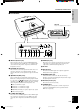
Part Names and Functions ■ Front panel and controls STANDBY/ON indicator Front remote control sensor Lamp cover Ventilation inlet Ventilation (Exhaust) vent Lens Lens cover Adjuster Use this to make fine adjustments to the projection angle. STANDBY/ON 1 2 3 4 MENU ESCAPE PATTERN SETTING 5 ASPECT 6 7 1 STANDBY/ON indicator 2 STANDBY/ON button Switches the unit between Standby and On (operational) modes. 3 ESCAPE button Use this button to exit from submenu mode.
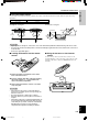
■ Connections INTRODUCTION Part Names and Functions AC inlet Plug in the supplied power cord here.
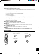
Part Names and Functions ■ Remote control 0 INPUT area Buttons with identical names to those on the main unit perform identical functions. To use the remote, point it at the remote control sensor on the front or back of the unit from a distance of no more than 7 m (23 feet). q MEMORY area Calls up stored video memory directly. w RESET button 1 2 3 4 5 6 Directly selects the input jack. e r AUTO V.
■ Using the remote control Use the remote control under the following conditions. The remote control will not function if it is used outside the angles and/or range detailed here.
Installation ■ Installation methods There are four ways to install this unit: on a table in front of the screen. mounted on the ceiling in front of the screen. on a table behind a semi translucent screen. mounted on the ceiling behind a semi translucent screen. Set the method you use on the 4 section of the MENU described later. (see page 21.) Place the unit on a standard height table to project and view the image from in front of the screen.
Installation ■ Screen and projection distance The ideal position for mounting the main unit (Projection distance [a]) depends on the size of the screen to be used (the length of a diagonal line across the screen). It is possible to adjust the projection distance within a preset range from Wide to Tele using the zoom function. Additionally, it is possible to adjust the V. POS (Vertical positioning) of the image to better suit the screen.
Installation ■ Projection image position Follow the instructions below to adjust the position of the projected image on the screen. Wide This figure shows the limits within which the zoom function can alter projection distance in relation to the screen size. Within these limits, it is possible to adjust the image so that it fills the screen completely. (See page 12.) Tele Lens center line
Connecting the unit • Make sure that the power of this unit and all other components is turned off before making any connections. • Some components have different connection methods and connector names. Refer to the operating instructions for each component that you wish to connect. • Plug the unit in correctly to prevent it from creating noise or other problems.
Connecting the unit ■ Connecting to a computer There are three ways of connecting a computer, as listed below. Please use the correct type of cable for the connector when making connections.
Basic Operations This section describes the basic operation of the DPX-1000 once installation and connection have been completed. It is necessary to make detailed settings in the menu described later so that the DPX-1000 is correctly set for the mounting, screen, input signals, and other conditions of its installation. Follow the steps described in this section to carry out these procedures. ■ Turning on the power ■ Turning off the power Be sure to remove the lens cover before using this unit. 1.
Basic Operations ■ Preparations for projection Carry out the adjustments necessary to the projection image to obtain the optimum setting for projection. Adjust the focus of the projected image. ZOOM ESCAPE SETTING PATTERN AUTO V. POS MENU ESCAPE IRIS V. POS ZOOM FOCUS FOCUS IRIS SETTING PATT PATT SETTING ESCAPE ASPECT ESCAPE COVER TEMP 2.
Basic Operations ■ Select an input Press the INPUT button to display the input selection menu on the screen. Use the h and g to select a name from those on display and then press the to confirm your choice. The signal settings for INPUT A, INPUT B and DVI will not change. To change them, press the + button to open the submenu, use the cursor buttons to select a suitable source from Component/ RGB PC/RGB TV, and confirm the selection by pressing the button.
Basic Operations ■ Select a display aspect Display aspect selects the type of image to display for an input signal. Press the ASPECT button and select a suitable mode. The types of aspect mode available depend on the input signal. Additionally, this unit has an auto mode that can automatically select the correct display aspect if the relevant information is encoded in the input signal. These modes are accessible from the display aspect area of the 2 section of the menu described later.
Basic Operations ■ Other functions ■ Indicators STILL — freezing the image There are 5 indicators on the main unit that display the operating status of the DPX-1000. Press the STILL button on the remote control to capture a frame from a moving image. Press STILL once more to resume normal projection.
Menu structure It is necessary to set various properties on a variety of menus so that this unit can project in optimal condition. There are four menu groups, each with a number of different menu items. Some of these items are not selectable for certain types of input signal, some have submenus attached, and others have a three stage menu hierarchy. (Displayed with a S overleaf.) Each menu group consists of the items below.
Menu structure ■ 1 ........ You cannot adjust these settings without an input signal. Input signal Video/Component, RGB TV Video/Component, RGB TV, *RGB PC *RGB PC Menu Item BLACK LEVEL Adjusts the level of blackness in an image while maintaining peak white brightness. Increasing the black level will increase the luminosity of dark scenes and clarify picture tone, however it will also lower the contrast.
Menu structure Input signal Video/Component, RGB TV Video/Component, RGB TV Video/Component, RGB TV, RGB PC Menu Item SHARPNESS TYPE Use this parameter to change the filtering characteristics of the circuitry used to sharpen edges in the projected image. SHARPNESS GAIN Adjusts the clearness of the image edges. The higher value creates clearer edges. The lower value creates a softer image with less noise element. COLOR BALANCE S The default setting displays a good balance of colors, which you cannot change.
Menu structure ■ 2 ...... You cannot adjust the parameters below if the unit is not receiving an input signal. Input signal Video/Component, RGB TV, RGB PC Video(NTSC) Video/Component, RGB TV Video Video/Component, RGB TV Video/Component Video/Component, RGB TV Component, RGB TV RGB TV *RGB PC *RGB PC *RGB PC Video/Component, RGB TV, RGB PC Depending on the state of the input source, it may not be possible for the unit to automatically select the optimal display mode.
Menu structure ■ 3 Menu item COLOR SYSTEM S Selects the color system to use when the input signal is from a video source. Available selections are NTSC, NTSC4.43, PAL, PAL-M, PAL-N, PAL60, and SECAM. Usually, setting the unit to AUTO will result in the unit automatically selecting the appropriate color method. However, since the unit does not automatically detect NTSC4.43 under AUTO mode, set the color method to NTSC4.43 manually to view NTSC4.43 images.
Menu structure ■ 4 Menu item LOCATION S There are four ways of installing this unit; tabletop or ceiling mounting for front or rear projection. The DPX-1000 will invert or rotate the projection according to this setting. KEYSTONE If the projection unit is at a horizontal or perpendicular angle to the screen the projection image will be distorted to a trapezoid shape. Use the KEYSTONE setting to electronically correct without increasing the length of the image.
Menu operation ■ Menu screen and operating buttons This section provides you with general information about the menu screen and operating buttons on the remote control and this unit’s control panel for easier operation. Please read it carefully before starting to operate the menu. There are four menu groups in the menu, each containing various menu items. Some menu items also have submenus, making up a 3 tier hierarchy.
Menu operation ■ Basic menu operation To ensure proper projection, start with setting and adjustment in menu group “SETUP”. STANDBY/ON INPUT ASPECT LIGHT AUTO STILL V. POS ZOOM HIDE FOCUS INPUT S VIDEO IRIS 1, 6 5 SETTING A DVI VIDEO B D4 1 2 3 4 5 6 3, 5 PATTERN SETTING 3, 5 4 RESET 2, 4 1, 6 MEMORY MENU ESCAPE MENU ESCAPE 5 PATT 2, 4 ASPECT INPUT LAMP COVER TEMP FAN INPUT ASPECT 1. Press MENU to open the menu. 3. Press g to enter the menu item hierarchy.
Menu operation Some items are adjusted by increasing or decreasing the value on the scale, and others by selecting a number or a word. Black Level Gamma Trim A B C D E Press the RESET button to reset the parameter to the factory setting. (Items without a factory setting cannot be reset.) ■ Submenus Following is a list of the menu items that have a submenu. Submenu operation varies according to the menu item selected. Follow the steps of the applicable submenu operation group.
Menu operation ■ Basic submenu operation 3. Select the submenu parameter by pressing h or g. [Operation groups A and B] or 1. Select the menu item to be adjusted by following steps 1—3 in “Basic menu operation”. The submenu mark “ ” appears on the right side of the item.
Menu operation ● Submenu operation — “COLOR BALANCE” 4. Use h, g, +, and – to set the gauge figures to your liking. Press the RESET button to reset the parameter to the factory setting. [Operation group C] 1. Follow steps 1—3 in “Basic menu operation” to select the menu item “COLOR BALANCE” in menu group . The submenu mark “ ” appears on the right side of the item.
Menu operation 3. Select “YES” with h or g, and then press . 3. Press h or g to select the submenu item to reset. LAMP RUNNING TIME will reset to 0 hour.
Menu operation ■ One-touch image menu ■ Changing the menu location 1. Press 1. Press ESCAPE or h to return the cursor to the menu when the menu screen is not open. Menu items appear one by one at the bottom of the screen. The display will disappear if no operation is performed within five seconds. group. ESCAPE ESCAPE or or Remote control Remote control Move Menu hg Window Control panel Image hg Black Level 2. Press h or g to select a menu item to adjust.
Memory function This unit has a memory function able to store six settings for projecting different types of input sources in the most appropriate manner. Select the setting that is most appropriate for your projection. Some settings may not be available depending on the type of input signal currently in use. Six settings have been preset, but each parameter can be changed and restored at will. The following lists the menu items that you can store in memory. 3. Press + to open the submenu.
Memory function ■ Resetting to the factory default settings For one parameter Follow steps 1—3 in “Basic menu operation” on page 23 to select the parameter to reset. Press the RESET button on the remote control to return the parameter to its factory default setting. (Items without a factory default cannot be reset.) To reset all parameters in all six memory settings Follow the directions in “Submenu operation—RESET” on page 27 to select “ALL MEMORIES” on the submenu.
AAAAA Additional information ■ Glossary D connector This connector is designed for the Japanese D format only. It is used for sending and receiving the image signal between the latest type of A/V components. This connector can receive the component signal by using a D connector cable. There are five levels (D1—D5) of performance characteristics. This unit is compatible with D1, 2, 3, and 4. The following is a list of key words and their explanations used in the use of projectors and image signals.
Additional information HDCP High-bandwidth Digital Content Protection system. HDCP is designed to protect the video transmission between a DVI transmitter and a display device. Aspect This refers to the length-to-width ratio of an image. Ceiling mount bracket This is the mounting hardware used to hand this unit from the ceiling. Two types of bracket are available, for high and low ceilings. Ceiling mount brackets are sold separately.
Additional information ■ Projectable signals The following charts show the types and formats of the signals that can be projected by this unit. Any signals not listed below may not be properly projected. 1. TV format 1 ------ Composite or S video signals sent to the VIDEO or S-VIDEO inputs Type of signal V active (lines) NTSC PAL SECAM PAL60 NTSC4.43 PAL-M PAL-N f (V) (Hz) 480 576 576 480 576 480 576 fsc (MHz) 59.94 50.00 50.00 59.94 59.94 59.94 50.00 Color system 3.58 4.43 4.406, 4.25 4.43 4.43 3.
Additional information ■ Message display Message Condition No Signal The unit is not receiving or detecting any signal at the selected input source. This message is displayed together with the name of the input source selected with the INPUT button. INPUT A (Component) (Example) The input name selected by the INPUT button is displayed. It will turn off 1 minute after the signal has been input. Out Of Range The unit is not able to decode the PC signal currently being input.
Maintenance ■ Regular care ■ Filter replacement Be sure to disconnect the power cable prior to doing any maintenance. Replace the filter when it becomes difficult to remove dust from it. 1. Turn off the power and disconnect the power cable Wipe with a soft cloth. Use a damp cloth with a mild detergent and then wipe with a dry cloth again if the unit is heavily soiled. Do not use strong solvents such as thinner or alcohol as they may damage the case of this unit. from this unit. 2.
Maintenance ■ Replacing the lamp cartridge 3. Loosen the screws of the lamp cartridge. Important • Be sure to use the replacement lamp cartridge PJL 327. Other lamp cartridges are not suitable for use in this unit. The lamp used as a light source in this unit is a consumable and will gradually lose its brightness during the course of use. It is advisable to replace the lamp when running time has exceeded 2000 hours. You can view the current lamp running time in 3 on the menu.
Troubleshooting Refer to the chart below when this unit does not function properly. If the problem you are experiencing is not listed below or if the instruction below does not help, set this unit in the standby mode, disconnect the power cord, and contact the nearest authorized YAMAHA dealer or service center. Problem Cause This unit does not turn on. No picture Remedy The power cable is not plugged in. Plug the power cable in firmly.
Specifications ■ Specifications Controls Optical Remote ........................................................ RS-232C (D-Sub 9 pin) Projection mode .......................... DLP™ (Digital Light Processing) Images of 1280 x 720 pixels, 0.8 inch Lens ................................................... f=24.4 to 39 mm F=2.4 to 3.1 Electronic zoom (x 1.6) Electronic focus Lamp ..................................................................... 270 W SHP lamp Image size ................................
G/Y B/PB/CB VD OUT REMOTE IN RS-232C S-VIDEO TRIGGER OUT VIDEO ADDITIONAL INFORMATION HD/SYNC English 03.2.19, 12:11 PM INPUT A 39 R/PR/CR 107_DPX-1000(E)31-39 360 14"-3/16 132.1 5"-3/16 DVI D4 VIDEO 10 3/8 189.5 7"-1/2 119.1 4"-3/5 INPUT B RGB/YPBPR/YCBCR 124 4"-7/8 (257.5 10"-1/8) PATTERN LAMP COVER TEMP FAN INPUT MENU 495 19"-1/2 DIGITAL CINEMA PROJECTOR DPX-1000 ASPECT ESCAPE STANDBY/ON SETTING 237.5 9"-3/8 Specifications ■ Dimensional drawing 465.
YAMAHA YAMAHA YAMAHA YAMAHA YAMAHA YAMAHA YAMAHA ELECTRONICS CORPORATION, USA 6660 ORANGETHORPE AVE., BUENA PARK, CALIF. 90620, U.S.A. CANADA MUSIC LTD. 135 MILNER AVE., SCARBOROUGH, ONTARIO M1S 3R1, CANADA ELECTRONIK EUROPA G.m.b.H. SIEMENSSTR. 22-34, 25462 RELLINGEN BEI HAMBURG, F.R. OF GERMANY ELECTRONIQUE FRANCE S.A. RUE AMBROISE CROIZAT BP70 CROISSY-BEAUBOURG 77312 MARNE-LA-VALLEE CEDEX02, FRANCE ELECTRONICS (UK) LTD. YAMAHA HOUSE, 200 RICKMANSWORTH ROAD WATFORD, HERTS WD1 7JS, ENGLAND SCANDINAVIA A.