
Service manual

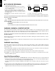


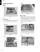
Table Of Contents
- CONTENTS
- TO SERVICE PERSONNEL
- WARNING: CHEMICAL CONTENT NOTICE!
- WARNING: Laser Safety
- Laser Emitting conditions:
- Laser Diode Properties
- WARNING
- WARNING LOCATION: REAR PANEL
- Warning for power supply
- PREVENTION OF ELECTRO STATIC DISCHARGE
- LOCALE MANAGEMENT INFORMATION
- FRONT PANELS
- REMOTE CONTROL
- REAR PANELS
- SPECIFICATIONS
- DISASSEMBLY PROCEDURES
- SERVICE POSITION
- DIAGNOSTIC SOFTWARE
- 1. End User/Dealer Script Interface
- 2. Player Script Interface
- 3. Menu and Command Mode Interface
- 4. Nuclei Error Codes
- 5. Loop tests
- 5.1 Nucleus 900: Digital Audio Loop
- 5.2 Nucleus 901: Audio User Dealer Loop
- 5.3 Nucleus 902: Digital Video Loop
- 5.4 Nucleus 903: Digital Video VBI Loop
- 5.5 Nucleus 904: System Video Loop
- 5.6 Nucleus 905: System Video VBI Loop
- 5.7 Nucleus 906: Video User Dealer Loop
- 5.8 Nucleus 907: Video VBI User Dealer Loop
- 5.9 Nucleus 908: System Audio Loop Scart (Europe)
- 5.10 Nucleus 909: System Audio Loop CINCH (Nafta)
- FAULTFINDING TREES
- ALIGNMENTS
- CIRCUIT DESCRIPTION
- ABBREVIATION LIST
- IC DATA
- BLOCK DIAGRAM
- WIRING DIAGRAM
- PRINTED CIRCUIT BOARD
- SCHEMATIC DIAGRAM
- POWER SUPPLY P.C.B. (A,B,G models)
- DISPLAY
- FRONT AV INPUT
- IR AND STANDBY
- FRONT DV INPUT
- ANALOG P.C.B. (U model)
- ANALOG P.C.B. (A,B,G models)
- ANALOG: All in One 1
- ANALOG: All in One 2
- ANALOG: TUNER / DEMODULATOR
- ANALOG: IN /OUT 1
- ANALOG: IN /OUT 2
- ANALOG: IN /OUT 3
- ANALOG: IN /OUT 4
- ANALOG: SOUND PROCESSING
- ANALOG: FOLLOW ME
- ANALOG: VPS
- ANALOG: POWER SUPPLY
- ANALOG: AUDIO CONVERTER
- ANALOG: RGB- YUV- CONVERTER
- ANALOG: DIGITAL IN / OUT
- ANALOG: FAN CONTROL
- DVIO
- DIGITAL
- DIGITAL: VSM, BUFFER MEMORY AND BIT ENGINE INTERFACE
- DIGITAL: AV DECODER STI5508
- DIGITAL: AV DECODER MEMORY
- DIGITAL: VIDEO ENCODER, EMPRESS
- DIGITAL: VIP CVBS Y/ C VIDEO INPUT
- DIGITAL: ANALOG P. C. B. CONS. VIDEO IN / OUTPUT
- DIGITAL: PROGRESSIVE SCAN
- DIGITAL: PROGRESSIVE SCAN
- DIGITAL: POWER, CLOCK, AND RESET AUDIO CLOCK
- EXPLODED VIEW (U model)
- EXPLODED VIEW (A, B, G models)
- MECHANICAL PARTS
- EXPLODED VIEW (FRONT ASS’Y)
- MECHANICAL PARTS (Front Ass’y)
- MECHANICAL PARTS (Accessories)
DRX-1
DRX-1
4
1
2
4
2
5
5
4
2
6
3
5
■ LOCALE MANAGEMENT INFORMATION
Locale Management Information : This DVD recorder is designed and manufactured to respond to the Locale Management
Information that is recorded on the DVDR disc. If the Locale number described on the DVDR disc does not correspond to the
Locale number of this DVD recorder, this DVD recorder cannot play this disc.
This product incorporates copyright protection
technology that is protected by method claims of
certain U.S. patents and other intellectual
property rights owned by Macrovision
Corporation and other rights owners. Use of this
copyright protection technology must be
authorized by Macrovision Corporation, and is
intended for home and other limited viewing uses
only unless otherwise authorized by Macrovision
Corporation. Reverse engineering or
disassembly is prohibited.
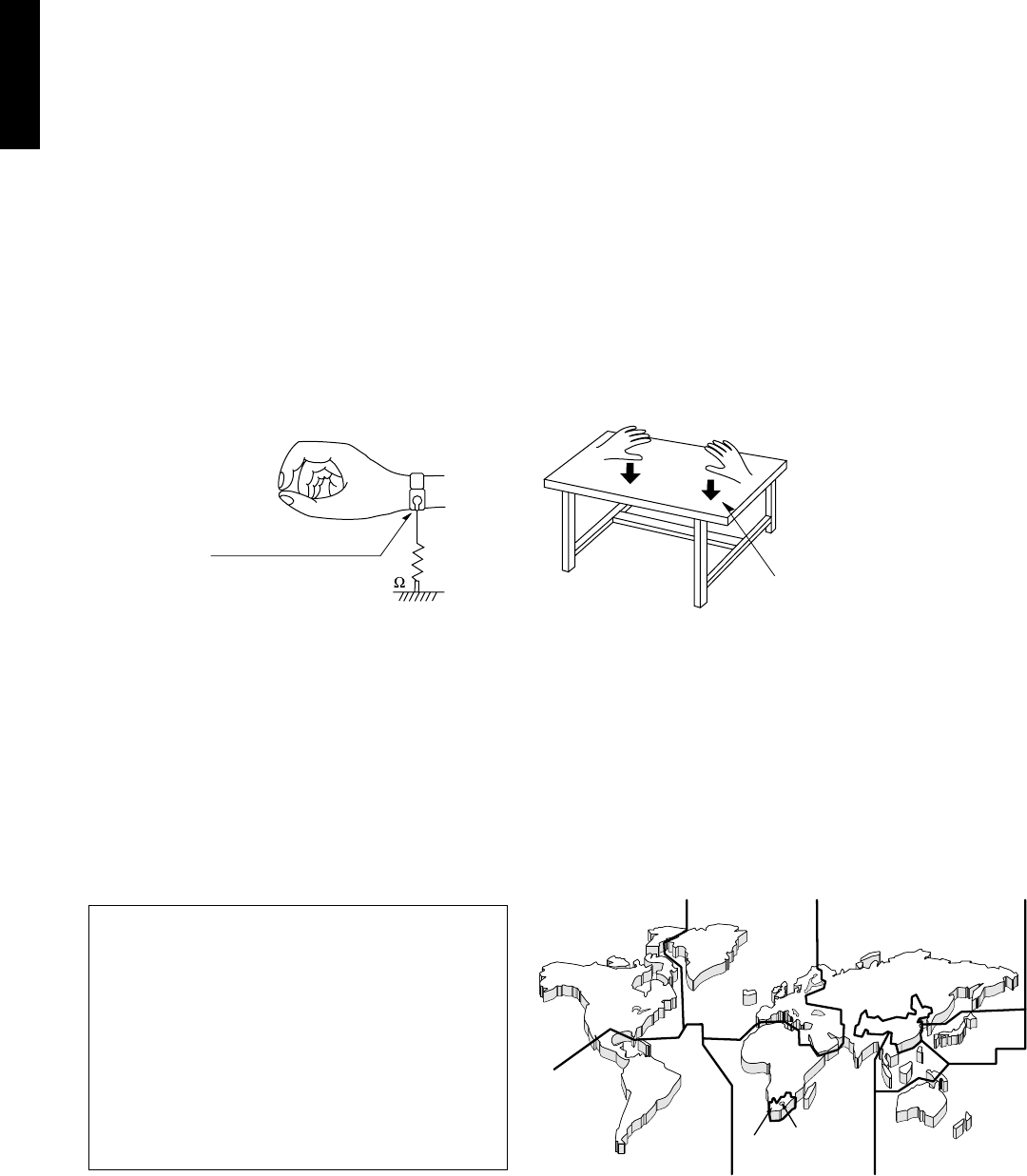
■ PREVENTION OF ELECTRO STATIC DISCHARGE
The laser diode in the DVDR mechanism may be damaged due to static electricity from clothes or the human body. Use
caution to prevent electrostatic damage when servicing or handling the DVDR mechanism.
1. Grounding for electrostatic damage prevention
Some devices, such as the DVD recorder, use an optical pickup (laser diode) that will be damaged by static electricity in the
working environment. Only attempt service after ensuring that all grounding procedures have been completed.
1. Worktable grounding
Put a grounded conductive material (sheet) or iron sheet on the area where the optical pickup is placed.
2. Human body grounding
Use an anti-static wrist strap to discharge the static electricity from your body.
1M
Conductive material
(sheet) or steel sheet
Anti-static wrist strip
2. Handling Precautions for DVDR mechanism
1. Handle the DVDR mechanism gently, as it is an extremely high-precision assembly.
2. The flexible cable lines may break if an excessive force is applied to it. Use caution when handling the cable.
3. The semi-fixed resistor for laser power adjustment should not be adjusted. Do not turn the resistor.