
Service manual
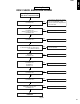
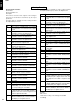
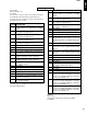
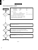
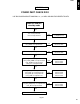
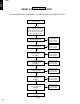
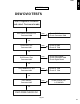
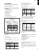
Table Of Contents
- CONTENTS
- TO SERVICE PERSONNEL
- WARNING: CHEMICAL CONTENT NOTICE!
- WARNING: Laser Safety
- Laser Emitting conditions:
- Laser Diode Properties
- WARNING
- WARNING LOCATION: REAR PANEL
- Warning for power supply
- PREVENTION OF ELECTRO STATIC DISCHARGE
- LOCALE MANAGEMENT INFORMATION
- FRONT PANELS
- REMOTE CONTROL
- REAR PANELS
- SPECIFICATIONS
- DISASSEMBLY PROCEDURES
- SERVICE POSITION
- DIAGNOSTIC SOFTWARE
- 1. End User/Dealer Script Interface
- 2. Player Script Interface
- 3. Menu and Command Mode Interface
- 4. Nuclei Error Codes
- 5. Loop tests
- 5.1 Nucleus 900: Digital Audio Loop
- 5.2 Nucleus 901: Audio User Dealer Loop
- 5.3 Nucleus 902: Digital Video Loop
- 5.4 Nucleus 903: Digital Video VBI Loop
- 5.5 Nucleus 904: System Video Loop
- 5.6 Nucleus 905: System Video VBI Loop
- 5.7 Nucleus 906: Video User Dealer Loop
- 5.8 Nucleus 907: Video VBI User Dealer Loop
- 5.9 Nucleus 908: System Audio Loop Scart (Europe)
- 5.10 Nucleus 909: System Audio Loop CINCH (Nafta)
- FAULTFINDING TREES
- ALIGNMENTS
- CIRCUIT DESCRIPTION
- ABBREVIATION LIST
- IC DATA
- BLOCK DIAGRAM
- WIRING DIAGRAM
- PRINTED CIRCUIT BOARD
- SCHEMATIC DIAGRAM
- POWER SUPPLY P.C.B. (A,B,G models)
- DISPLAY
- FRONT AV INPUT
- IR AND STANDBY
- FRONT DV INPUT
- ANALOG P.C.B. (U model)
- ANALOG P.C.B. (A,B,G models)
- ANALOG: All in One 1
- ANALOG: All in One 2
- ANALOG: TUNER / DEMODULATOR
- ANALOG: IN /OUT 1
- ANALOG: IN /OUT 2
- ANALOG: IN /OUT 3
- ANALOG: IN /OUT 4
- ANALOG: SOUND PROCESSING
- ANALOG: FOLLOW ME
- ANALOG: VPS
- ANALOG: POWER SUPPLY
- ANALOG: AUDIO CONVERTER
- ANALOG: RGB- YUV- CONVERTER
- ANALOG: DIGITAL IN / OUT
- ANALOG: FAN CONTROL
- DVIO
- DIGITAL
- DIGITAL: VSM, BUFFER MEMORY AND BIT ENGINE INTERFACE
- DIGITAL: AV DECODER STI5508
- DIGITAL: AV DECODER MEMORY
- DIGITAL: VIDEO ENCODER, EMPRESS
- DIGITAL: VIP CVBS Y/ C VIDEO INPUT
- DIGITAL: ANALOG P. C. B. CONS. VIDEO IN / OUTPUT
- DIGITAL: PROGRESSIVE SCAN
- DIGITAL: PROGRESSIVE SCAN
- DIGITAL: POWER, CLOCK, AND RESET AUDIO CLOCK
- EXPLODED VIEW (U model)
- EXPLODED VIEW (A, B, G models)
- MECHANICAL PARTS
- EXPLODED VIEW (FRONT ASS’Y)
- MECHANICAL PARTS (Front Ass’y)
- MECHANICAL PARTS (Accessories)
DRX-1
DRX-1
64
DISPLAY PCB OK.
NO DISC
POWER ON
DISPLAY?
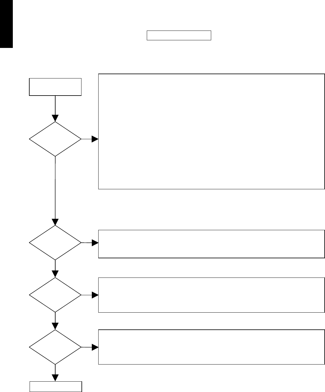
Check presence of low pulses at pin 5 of connector 1917 while pressing a key on remote control.
Check IR receiver 7140.
Diagnostic software “Player script” : Remote control test.
Check if voltage at connector 1915-2 is 5V when power on (green light)
Check if voltage at base of Tr 7141 is 2V when power on (green light).
Check if voltage at base of Tr7141 is 0V when switching to standby (red light)
Diagnostic software “Player script” : LED test.
Diagnostic software “Player script” : Keyboard test.
Check appropriate key and resistor
Check supply voltage
Connector1916-2 12STBY +12V
Connector1916-3 VGNSTB -32V
Connector1916-11 5STBY +5V
Connector1916-12 5M +5.2V
Testpoint F105 12STBYSI +12V
Check filament voltage
AC voltage is created via oscillator circuit (7152-7153).
Check heater voltage on testpoints F102 and F101 3.2VAC, -24,4VDC, 42 kHz.
Check oscillator frequency of 12MHz at pin 91 of IC7156
Check I2C bus SDA / SCL nucleus 500 of diagnostic software
Check version of software nucleus 501 of diagnostic software
Diagnostic software : Player script of Front panel
NO
YES
Key Function
NO
YES
Standby LED ?
YES
Remote control?
NO
YES
TROUBLESHOOTING DISPLAY BOARD
NO
Fig. 21
5. Display Board