NATURAL SOUND AV AMPLIFIER CINEMA DSP 7ch DSP–A1092 VOLUME l6 VCR 2 VCR 1 20 DVD/LD l2 28 8 60 2 POWER VIDEO AUX TAPE (MD) TV/DBS TUNER PHONO CD 4 40 0 –dB l ON OFF 0 l 2 3 4 A PHONES SPEAKERS 4 5 B BASS TONE EXTENSION BYPASS l 2 3 5 0 l 2 l 2 3 3 4 4 5 5 0 SOURCE DVD/LD l 2 2 3 3 4 4 L5 5R TAPE (MD) TV/DBS TUNER VCR 1 CD VCR 2 PROGRAM VIDEO AUX SET MENU BASS TREBLE BALANCE Natural Sound AV Amplifire Amplificateur audiovisuel “Son Natu
Congratulations! You are the proud owner of a Yamaha Digital Sound Field Processing (DSP) System—an extremely sophisticated audio component. The DSP system takes full advantage of Yamaha’s undisputed leadership in the field of digital audio processing to bring you a whole new world of listening experiences.
PRECAUTIONS & SAFETY INSTRUCTIONS Keep the unit away from locations where it is likely to be exposed to high temperatures or humidity—such as near radiators, stoves, etc. Also avoid locations which are subject to excessive dust accumulation or vibration which could cause mechanical damage. 2. INSTALL THE UNIT IN WELL-VENTILATED CONDITION The openings on the cabinet assure proper ventilation of the unit. If these openings are obstructed, the temperature inside the cabinet will rise rapidly.
CONTENTS PRECAUTIONS & SAFETY INSTRUCTIONS ...................................1 GETTING STARTED ...........................................................................3 FEATURES ..........................................................................................5 SPEAKER SETUP.............................................................................10 CONTROLS & THEIR FUNCTIONS.................................................13 FRONT PANEL........................................................
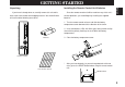
GETTING STARTED Installing the Remote Control Unit Batteries If you haven’t already done so, carefully remove this unit and its accessories from the box and wrapping material. You should find the unit itself and the following accessories. Since the remote control unit will be used for many of this unit’s control operations, you should begin by installing the supplied batteries. English Unpacking 1.
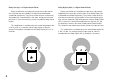
Notes about the Remote Control Unit ● ● When you notice that remote control operation has become erratic, or the distance from which the remote control will function has decreased, it’s time to replace the batteries. Always replace all batteries at the same time. This remote control uses an advanced, highly directional infrared beam. Be sure to aim the remote control directly at the remote control sensor on the main unit when operating.
FEATURES In addition, this unit incorporates a Dolby Pro Logic Surround decoder and Dolby Digital (AC-3) decoder for multi-channel sound reproduction of Dolby Surround encoded video sources. The operation of the Dolby Pro Logic Surround or Dolby Digital (AC-3) decoder can be controlled by selecting a corresponding DSP program including combined operations of the Yamaha DSP and the Dolby Pro Logic Surround or Dolby Digital (AC-3) decoder.
6 Dolby Pro Logic Surround Dolby Digital (AC-3) This unit employs a Dolby Pro Logic Surround decoder similar to professional Dolby Stereo decoders used in many movie theaters. By using the Dolby Pro Logic Surround decoder, you can experience the dramatic realism and impact of Dolby Surround movie theater sound in your own home. Dolby Pro Logic employs a four channel five speaker system.
Manufactured under license from Dolby Laboratories Licensing Corporation. “Dolby”, “AC-3”, “Pro Logic”, and the double-D symbol are trademarks of Dolby Laboratories Licensing Corporation. Copyright 1992 Dolby Laboratories, Inc. All rights reserved. The following original functions make the surround-sound effect of Dolby Digital (AC-3) become the most suitable for your audio system and the listening conditions.
Dolby Pro Logic + 2 Digital Sound Fields Dolby Digital (AC-3) + 3 Digital Sound Fields Digital sound fields are created on the presence side and the rear surround side of the Dolby Pro Logic Surround-decoded sound field respectively. They create a wide acoustic environment and emphasize surround-effect in the room, letting you feel much presence as if you are watching a movie in a popular Dolby Stereo theater.
If you connect your video cassette recorder, LD player, video monitor, etc. to this unit, you can take advantage of this unit’s capability to display program titles and information for various setting changes and adjustments on your video monitor’s screen. This information will be superimposed over the video image. English Video superimpose If there is no video source connected or it is turned off, the information will be displayed over a blue colored background.
SPEAKER SETUP Setting Up Your Speaker System Use of the Center Dialog Speaker Is Recommended This unit has been designed to provide the best sound field quality with a full seven-speaker system setup, using two extra pairs of effect speakers to generate the sound field plus one center speaker for dialog. We therefore recommend that you use a sevenspeaker setup.
4 Speaker System 5 Speaker System 6 Speaker System 7 Speaker System Simplest system. Good for Audio/Video sources. Good for sound fields from 2channel stereo sources. This is the recommended speaker system, providing the best sound effects. You can enjoy widely diffused sound by only adding two additional speaker units at the rear. By the use of center speaker, center sounds (dialog, vocals etc.) are precisely localized. When a normal stereo source is played back with the sound field programs No.
Speakers and Speaker Placement Your full seven-speaker system will require three speaker pairs: the MAIN SPEAKERS (your normal stereo speakers), the FRONT EFFECT SPEAKERS and the REAR SPEAKERS, plus the CENTER SPEAKER. You may also be using a subwoofer. The MAIN SPEAKERS should be high performance models and have enough power handling capacity to accept the maximum output of your audio system. Other speakers do not have to be equal to the MAIN SPEAKERS.
CONTROLS & THEIR FUNCTIONS English FRONT PANEL 1 2 3 4 5 6 (Europe Model) NATURAL SOUND AV AMPLIFIER CINEMA DSP 7ch DSP–A1092 VOLUME l6 VCR 2 VCR 1 20 DVD/LD l2 28 8 POWER VIDEO AUX TAPE (MD) TV/DBS TUNER PHONO CD 4 40 2 60 0 –dB l ON OFF 0 l 2 3 4 A PHONES 7 * SPEAKERS 8 BASS TONE EXTENSION BYPASS 9 0 0 l 2 3 4 5 l 2 3 4 5 B l 2 3 DVD/LD l 2 5R TUNER VCR 1 PROGRAM CD VCR 2 4 L5 5 TAPE (MD) TV/DBS 3 4 4 5 SOURCE 0 2 3 VIDEO AUX S
1 POWER Switch Turns this unit on and off. * When you press this switch to turn the power on, you will hear a click and a sound of the built-in fan rotating for a moment. 2 Standby Indicator While the power of this unit is on, pressing the (SYSTEM POWER) OFF key on the remote control unit switches this unit to the standby mode. In this mode, the standby indicator is illuminated. 3 Remote Control Sensor Signals from the remote control unit are received here. 4 Display Panel See page 16.
Sequentially selects the digital sound field processing programs in the + or – direction. E SET MENU Switch Whenever pressed, selects functions in the SET MENU mode. F DELAY/C/R/F/SWFR Switch Whenever pressed, selects the item of changing delay time, center speaker output level, rear speaker output level, front effect speaker output level and subwoofer output level in turn. * Depending on a mode of this unit, the number of selections is reduced.
DISPLAY PANEL 1 2 DIGITAL ENHANCED 70 mm mS dB SPEAKERS SPEAKERS A B PCM 3 1 Input Source Display Shows the currently selected input source. 2 Multi-informatiom Display Shows the currently selected DSP program, or information for several adjustments or setting changes made on this unit. 3 SPEAKERS A/B Indicators The indicator A or B which corresponds to the currently selected main speakers lights up. If both main speakers A or B are selected, both indicators light up.
CONNECTIONS English REAR PANEL PARTS AND THEIR FUNCTIONS Before you start making connections make sure all related electronic components are turned OFF. 1 2 3 4 5 6 7 8 9 (General Model) AUDIO SIGNAL PCM/ DIGITAL IN COAXIAL DVD/LD TV/DBS TV/DBS IN IN VCR 1 VCR 1 OUT OUT 4 IN IN VCR 2 VCR 2 C D C OR D C D OUT MONITOR OUT PAL NTSC A I00W MAX.
1 PCM/ DIGITAL IN (COAXIAL and OPTICAL) jacks Can be connected with audio/video units that have a coaxial or optical digital output jack. Connect a unit that is connected to the DVD/LD AUDIO/VIDEO SIGNAL connection jacks to the DVD/LD COAXIAL or OPTICAL jack. Connect a unit that is connected to the TV/DBS AUDIO/VIDEO SIGNAL connection jacks to the TV/DBS COAXIAL or OPTICAL jack.
Main-channel line output. Connected with jumper bars to MAIN IN jacks when the built-in amplifier is used. Connected to input jacks of external stereo power amplifier (MAIN IN or TAPE PLAY jacks of integrated amplifier or receiver) when using external amplification. E MAIN IN Jacks Line input to built-in main-channel amplifier. Connected with jumper bars to PRE OUT jacks when the built-in amplifier is used. Not connected when using an external power amplifier.
REAR PANEL SWITCH AND CONTROL SETTINGS GENERAL INSTRUCTIONS FOR CONNECTIONS There are several switches and controls on the rear panel that you’ll have to check before operating your system, and it’s a good idea to do it before you connect cables. Locate the MAIN LEVEL slide switch (C) and FRONT MIX slide switch (B). Make sure the MAIN LEVEL switch is set to “0 dB” and the FRONT MIX switch is set to “OFF” for 7 or 6 speaker driving.
English CONNECTING AUDIO/VIDEO SOURCE EQUIPMENT TO THIS UNIT BASIC CONNECTIONS * If you have YAMAHA audio/video unit numbered as 1, 2, 3, etc. on the rear panel, connections can be made easily by making sure to connect the output (or input) terminals of each unit to the same-numbered terminals of this unit.
CONNECTING TO DIGITAL (OPTICAL AND COAXIAL) JACKS If your LD (DVD) player, TV/satellite tuner, etc. are equipped with coaxial or optical digital audio signal output jacks, they can be connected to this unit’s COAXIAL and/or OPTICAL digital signal input jacks.
If your LD player has AC-3 RF signal output jack and no digital signal output jack for AC-3 discrete audio signals, connect the AC3 RF signal output jack to this unit’s OPTICAL (or COAXIAL) digital signal input jack by using an RF demodulator (separate purchase). First, connect the AC-3 RF signal output jack of the LD player to the AC-3 RF signal input jack of the RF demodulator.
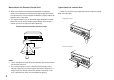
CONNECTING TO S VIDEO JACKS LD (DVD) player VIDEO OUT S-VIDEO OUT Video cassette recorder 1 TV/Satellite tuner DVD/LD DVD/LD TV/DBS TV/DBS S-VIDEO OUT OUT OUT IN IN VCR 2 VCR 2 OUT OUT MONITOR OUT MONITOR OUT 24 PAL NTSC VIDEO IN Notes about the Video superimpose ● If you watch a video source that is connected to both S VIDEO and VIDEO input jacks of this unit, signals of screen display information are output from only the S VIDEO MONITOR OUT jack.
Connect the SPEAKERS terminals to your speakers with wire of the proper gauge, cut as short as possible. If the connections are faulty, no sound will be heard from the speakers. Make sure that the polarity of the speaker wires is correct, that is, + and – markings are observed. If these wires are reversed, the sound will be unnatural and will lack bass. Do not let the bare speaker wires touch each other or any other metal part as this could damage this unit and/or speakers.
CONNECTING THE MAIN SPEAKERS TO THIS UNIT One or two sets of MAIN speakers can be connected to this unit. Main speaker A If you use two sets of MAIN speakers, connect one set to the MAIN SPEAKERS A terminals, and connect another set to the B terminals. If you use only one set of MAIN speakers, connect them to either the MAIN SPEAKERS A or B terminals. Make sure that the jumper bars between the PRE OUT and MAIN IN jacks on the rear panel are in place.
Connect the FRONT effect speakers to the FRONT EFFECT SPEAKERS terminals of this unit. If the FRONT effect speakers are not used, the FRONT MIX switch should be set to “ON”. Front effect speaker L Front effect speaker Center speaker Center speaker Center speaker English CONNECTING THE FRONT EFFECT SPEAKERS, REAR SPEAKERS AND THE CENTER SPEAKER(S) TO THIS UNIT R Connect the REAR speakers to the REAR SPEAKERS terminals of this unit. Connect the CENTER speaker to the CENTER SPEAKERS terminals.
ADDING A SUBWOOFER You may wish to add a subwoofer to reinforce the bass frequencies. This unit provides line-level subwoofer outputs. If you use one subwoofer, connect either of the SUBWOOFER jacks to the INPUT jack of the subwoofer amplifier, and connect the speaker terminals of the subwoofer amplifier to the subwoofer. If you wish to obtain more presence in your listening room, the use of two subwoofers is recommended.
IMPEDANCE SELECTOR Select the position whose requirements your speaker system meets. Be sure to switch this only when the power of this unit is turned off. English Switching the IMPEDANCE SELECTOR switch on the rear panel CENTER C OR D: 4ΩMIN./ SPEAKER SET SPEAKER MODE C D: 4ΩMIN./ SPEAKER SET SPEAKER MODE REAR 4ΩMIN./ SPEAKER MAIN A OR B: 4ΩMIN./ SPEAKER A B: 8ΩMIN./ SPEAKER FRONT EFFECT: 6ΩMIN./ SPEAKER CENTER C OR D: 8ΩMIN./ SPEAKER SET SPEAKER MODE C D: 4ΩMIN./ SPEAKER SET SPEAKER MODE REAR 8ΩMIN.
SELECTING THE OUTPUT MODES SUITABLE FOR YOUR SPEAKER SYSTEM This unit provides you the following four functions to determine the method of distributing output signals to speakers suitable for your audio system. When speaker connections are all completed, select a proper position on each function to make the best use of your speaker system. 4. CENTER SPEAKER 5. REAR SPEAKER 6. MAIN SPEAKER 7. LFE/BASS OUT DESCRIPTION OF EACH FUNCTION 4. CENTER SPEAKER 5.
7. LFE/BASS OUT Choices: SMALL/LARGE Preset position: LARGE Choices: MAIN/SWFR/BOTH Preset position: SWFR SMALL: Select this position if your main speakers do not have a high ability for bass reproduction. However, if your system does not include a subwoofer, do not select this position. In this position, low bass signals (below 90 Hz) at the main channels are output from the SUBWOOFER jacks (if the SWFR or BOTH position is selected on “7. LFE/BASS OUT”).
METHOD OF CHANGING SELECTIONS Operations should be made watching information on this unit’s display panel or the monitor screen. 3. Press “+” or “–” once or more so that the arrow points the position you will select. Remote control Front panel 1. Turn the power of this unit on. (If you want to display information on the monitor, turn the power of the monitor on.) or Front panel 4. Press once or more until the title of another function on which you will change the selection appears on the display.
SPEAKER BALANCE ADJUSTMENT 3. Press the adjust. or key to select the speaker whose level you will Remote control The adjustment of each speaker output level should be done at your listening position with the remote control unit. Otherwise, the result may not be satisfactory. NOTE: Be sure to use the remote control unit with the lid open. 1. Set the TIME/LEVEL·SET MENU switch on the remote control to the TIME/LEVEL position.
NOTE: If there is insufficient volume from the effect speakers, you may decrease the main speaker volume level by setting the MAIN LEVEL switch on the rear panel to “–10 dB”, and adjust each speaker level again. Volume controls on external power amplifiers may also be adjusted if necessary to achieve proper balance. 7. Adjust the front effect speaker level by pressing the + or – key so that it becomes almost as same as that of the main speakers.
ADJUSTMENTS IN THE “SET MENU” MODE 1. CENTER DELAY 2. DYNAMIC RANGE 3. LFE LEVEL 4. CENTER SPEAKER 5. REAR SPEAKER 6. MAIN SPEAKER 7. LFE/BASS OUT 8. INPUT MODE (TV/DBS) METHOD OF SETTING CHANGE AND ADJUSTMENT Operations should be made watching information on this unit’s display panel or the monitor screen. If you want to display information on the monitor, turn the power of the monitor on.
DESCRIPTIONS OF THE FUNCTIONS 1. CENTER DELAY (Adjusting the delay of center sounds (dialog etc.)) Control range: 0 ms to 5 ms (in 1 ms step) Preset value: 0 ms * This adjustment is effective only when the Dolby Digital (AC-3) is decoded and the signals of selected source encoded with the Dolby Digital (AC-3) contain center-channel signals. Adjusts the delay between the main sounds (at the main channels) and dialog etc. (at the center channel). The larger the value, the later the dialog etc. is generated.
Control range: –20 dB to 0 dB (in 1 dB step) Preset value: 0 dB * This adjustment is effective only when the Dolby Digital (AC-3) is decoded and the signals of selected source encoded with the Dolby Digital (AC-3) contain LFE signals. Adjusts the output level at the LFE (low frequency effect) channel. If the LFE signals are mixed with signals at other channels to output them from the same speakers, the ratio of LFE signal level to the level of other signals are adjusted.
GENERAL OPERATION PLAYING A SOURCE NOTE: If you will use the remote control unit, be sure to use it with the lid open. * To change the input mode for the DVD/LD or TV/DBS source, press the input selector button for the currently selected source once or more until the desired input mode (AUTO or ANALOG) is shown on the display panel. (See page 39 for details on switching the input mode.) Front panel 1. Set the master VOLUME control to minimum.
Switching the input mode (for DVD/LD and TV/DBS) This unit allows you to switch the input mode only for sources connected to the DVD/LD and TV/DBS input jacks (on the rear of this unit) that input two or three types of signals to this unit. English Notes on using the input selector buttons • Note that pressing on each input selector button selects the source which is connected to the corresponding input terminals on the rear panel.
Notes on input mode selection • To play back a source with the Dolby Digital (AC-3) decoded, set the input mode to “AUTO”. • When you want to enjoy a source which has normal 2-channel signals with a Dolby Pro Logic Surround program, select the ANALOG mode.
While recording a source by setting the REC OUT selector to the position other than SOURCE as described above, the following operations can be made at the same time. ● ● You can monitor the audio (or the audio and video) signals being recorded by selecting the recording unit (TAPE (MD), VCR 1 or VCR 2) with the corresponding input selector button. You can watch or listen to any other source by selecting it with the corresponding input selector button.
SELECTING SOUND FIELD PROGRAMS This unit has 10 programs for digital sound field processing, 6 from actual acoustic environments from around the world, and 4 programs for Audio/Video sources including sources encoded with Dolby Pro Logic surround or Dolby Digital (AC-3). When operating on the front panel: 1.
The EFFECT switch on the front panel and the EFFECT ON/OFF key on the remote control unit make it simple to compare the normal stereo sound with the fully processed effect sound. English CANCELING THE EFFECT SOUND To cancel the effect sound and monitor only the main sound, press the EFFECT ON/OFF key or the EFFECT switch. Press the EFFECT ON/OFF key or the EFFECT switch a second time to restore normal operation.
DESCRIPTIONS OF THE SOUND FIELD PROGRAMS The following list gives brief descriptions of the sound fields produced by each of the DSP programs. Keep in mind that most of these are precise digital recreations of actual acoustic environments. The data for them was recorded at the locations described using sophisticated sound field measurement equipment. * The channel level balance between the left rear speaker and the right rear speaker may vary depending on the sound field you are listening to.
DIGITAL MOVIE THEATER When the input signal is Dolby Digital ( DIGITAL Speaker output: main, center, rear, front effect 5. STADIUM When the input signal is analog or PCM audio ( DSP ) Speaker output: main, rear, front effect When the input signal is Dolby Digital ( DIGITAL DSP ) Speaker output: main, center, rear, front effect DSP English 3.
7. ROCK CONCERT 9. CHURCH When the input signal is analog or PCM audio ( DSP ) Speaker output: main, rear, front effect When the input signal is Dolby Digital ( DIGITAL DSP ) Speaker output: main, center, rear, front effect When the input signal is analog or PCM audio ( DSP ) Speaker output: main, rear, front effect When the input signal is Dolby Digital ( DIGITAL DSP ) Speaker output: main, center, rear, front effect This program is ideally suited for rock music.
In using the digital sound field processor including the Dolby Pro Logic Decoder or the Dolby Digital (AC-3) Decoder, you can adjust delay time between the main sound and effect sound, and each speaker output level as you prefer. NOTE: These adjustments can be made only when the effect DIGITAL (or PRO LOGIC ) is not sound is on.
Adjusting delay time Adjusting output level of the front effect, center, right rear and left rear speakers, and subwoofer You can adjust the time difference between the beginning of the sound from the main speakers and the beginning of the effect sound from the rear or front effect speakers. The larger the value, the later the effect sound is generated. This adjustment can be made to all programs individually. Program Control range (ms) 1. DOLBY PRO LOGIC DOLBY DIGITAL 2.
SETTING THE SLEEP TIMER 2. The unit will be turned off automatically at the selected SLEEP time. English If you use the SLEEP timer of this unit, you can make this unit turn off automatically. When you are going to sleep while enjoying a broadcast or other desired input source, this timer function is helpful. To cancel the selected SLEEP time NOTES • The SLEEP timer can be controlled only with the remote control unit.
REMOTE CONTROL UNIT BASIC OPERATIONS (When the lid is open) LEARN MACRO REC/PAUSE E G NAMES OF KEYS AND THEIR FUNCTIONS H TRANSMIT /LEARN CLEAR The remote control unit provided with this unit is designed to control all the most commonly used functions of this unit. If the CD player, tape deck, LD player etc. connected to this unit are YAMAHA components designed for remote control compatibility, then this remote control unit will also control various functions of each component.
Selects a DSP program when the built-in digital sound field processor (including the Dolby Pro Logic Surround Decoder or the Dolby Digital (AC-3) Decoder) is on. 5 TEST key 0 RESET button This button is inside the battery compartment. Press this button to “reset” the internal microcomputer which controls remote control operations. Microcomputer “reset” is necessary when the remote control freezes. * Pressing the RESET button will not erase learned functions.
F A/B/C indicators The position (A, B or C) selected by the A/B/C switch is shown in red. G A/B/C switch This switch must be used only when the lid of the remote control unit is open. (This switch will not function when the lid is closed.) Normally, set this switch to the “A” position. When controlling a Yamaha LD player by using the CD/LD player keys (2), set this switch to the “C” position.
Keys which can have three functions (1, 2, 3, 4) * In the “Learning-capable” keys, the keys of groups numbered TRANSMIT /LEARN CLEAR LEARN 1–4 in the illustration at left can have three functions. This is MACRO REC/PAUSE A/B TAPE A TUNER A DIR VCR 1 B STOP B DISC DVD/LD TV/DBS 2 A/B/C switch CD 1 VCR 2 C 3 PRESET 2 A/B/C/D/E DIGITAL/ MOVIE PRO LOGIC ENHANCED THEATER 4 1 2 3 TV SPORTS STADIUM DISCO 4 5 6 ROCK because they have three memory areas (A, B and C).
Empty keys (1, 2) About the lighting of keys These are empty keys. Each key can learn a function from another remote control unit. For example, the TV key is useful for storing the function of your TV’s power switch, and the VCR key can be used for your VCR’s power switch. When you press an input selector key, it lights up for about 3 seconds. NOTE If a key which has a preset function learns a new function, the preset function will not be deleted, but disabled.
CLEAR REMOTE CONTROL TRANSMITTER LEARN MACRO REC/PAUSE A/B TUNER VCR 1 DVD/LD TV/DBS TAPE Input selector keys TAPE CD When the lid of the remote control unit is closed, you can easily operate Yamaha components including learned functions by using the OPERATION CONTROL keys.
See the table below for a combination of an input selector key and key functions which the OPERATION CONTROL keys carry out. (Also, refer to the table on page 53.
• English NOTES • If the OPERATION CONTROL keys substitute for keys which has no function (empty), no command is carried out. According to your plan, store functions from other remote control units into an empty area of those keys. (Refer to pages 61 to 62 for the learning method.
MACRO OPERATIONS (When the lid is closed) Preset macro keys TRANSMIT /LEARN CLEAR TRANSMIT “Macro” is a command which defines a sequence of several operations. LEARN REC/PAUSE REMOTE CONTROL TRANSMITTER TAPE A CD 1 CD TUNER TUNER A VCR 1 DIR VCR 1 B STOP B DISC DVD/LD DVD/LD TV/DBS 2 TV/DBS VCR 2 VCR 2 C PRESET A/B/C/D/E DIGITAL/ MOVIE PRO LOGIC ENHANCED THEATER V-AUX 1 2 3 TV SPORTS STADIUM DISCO 5 6 4 PHONO Preset macro keys are originally preset with macros.
English Preset macro keys and the key functions which they carry out sequentially are as follows. (Also, refer to the table on page 53.
NOTES • A key in which no function is stored will carry out no command. • If it occurs that this unit will not receive the second command because the internal operation of the first command takes a long time, set the MACRO switch to the “SLOW” position, or add no function or repeat the same command between the first command and the next command. • If you will program the power on/off switching function of TV, VCR, etc.
1. Place this remote control unit and the other remote control unit so that they face each other. 3. If necessary, select the memory area by using the A/B/C switch on the side panel of the remote control unit. English LEARNING A NEW FUNCTION This remote control unit TV RTS O 1 M IU AD ST 5 2 Z Other remote control unit 3 IS D UB CL ES -A V H RC U CH 9 6 CO U X H P T O T C FE F EF /OF ON N O 4. Press the key on this remote control unit in which you will store a new function.
5. Press and hold the key (on the other remote control unit) which has the function you want to store. 3 D IS U X H P T -A V S TE H RC U CH 9 6 CO 0 1 B U CL ZZ JA 8 2 M IU AD ST 5 K OC TV RTS O 4 SP 1 O T C FE F EF /OF ON N O * When learning is finished, the TRANSMIT/LEARN indicator stops lighting and then begins flashing slowly. * If a signal is not successfully received, the TRANSMIT/LEARN indicator flashes rapidly and the mode prior to step 4 is restored.
A new macro can be programmed onto any preset macro key in place of preset functions. (See page 58 to know what keys are preset macro keys.) You can make as many as 13 new macro keys. A macro key can learn as many as seven functions of other keys. NOTE If you store a continuous command such as lowering of volume level, it will become a short command when it is carried out as a part of macro. 1. Press the MACRO button using the point of a mechanical pencil etc. TRANSMIT /LEARN CLEAR LEARN MACRO 3.
It is recommended to write down new key functions you stored on the provided user function stickers and paste them on the reverse side of the remote control unit or the reverse side of the remote control unit’s lid. CLEARING LEARNED FUNCTIONS To Clear a Learned Function 1. To clear a learned key function, press the LEARN button using the point of a mechanical pencil, etc. To clear a macro you made, press the MACRO button. or TRANSMIT /LEARN CLEAR LEARN MACRO A Flashes slowly. B C 2.
1. Select the kind of key functions all of which you want to clear by using the MACRO switch on the side panel of the remote control unit. SLOW QUICK OFF 3. Press and hold the CLEAR button again. While holding the CLEAR button pressed, press and hold the MASTER VOLUME and keys simultaneously until the indicator flashes 7 times. English To Clear All Learned Functions TRANSMIT /LEARN MACRO MUTE Flashes. OFF: Select this position if you want to clear all of the learned functions except macros.
TROUBLESHOOTING PROBLEM Power does not come on. The unit turns off suddenly soon after the power is turned on. Hum. No sound. No sound from the effect speakers. No sound from the front effect speakers. No sound from the center speaker. Poor bass reproduction. The sound suddenly goes off. The volume level cannot be increased, or sound is distorted. The sound field cannot be recorded. This unit will not operate properly. 66 POSSIBLE CAUSE AC cord not properly plugged in.
The remote control unit does not function properly. Learning cannot be made successfully. (The TRANSMIT/LEARN indicator does not light up or flash.) Continuous functions such as volume are learned, but operate only for a moment before stopping. POSSIBLE CAUSE The source unit is connected to this unit between digital jacks only. This unit is too close to the affected equipment. The power to this unit is off. WHAT TO DO Make additional connection between analog jacks.
SPECIFICATIONS Minimum RMS Output Power Per Channel Main (20 Hz – 20 kHz 0.02% THD 8Ω) ........................................... 80W+80W Center (20 Hz – 20 kHz 0.02% THD 8Ω) ................................................. 80W Front Effect (1 kHz 0.05% THD 8Ω)..................................................25W+25W Rear (20 Hz – 20 kHz 0.02% THD 8Ω) ........................................... 80W+80W Dynamic Power Per Channel (by IHF Dynamic Headroom Measuring Method) MAIN L/R (8Ω/6Ω/4Ω/2Ω) ............
YAMAHA YAMAHA YAMAHA YAMAHA YAMAHA YAMAHA YAMAHA ELECTRONICS CORPORATION, USA 6660 ORANGETHORPE AVE., BUENA PARK, CALIF. 90620, U.S.A. CANADA MUSIC LTD. 135 MILNER AVE., SCARBOROUGH, ONTARIO M1S 3R1, CANADA ELECTRONIK EUROPA G.m.b.H. SIEMENSSTR. 22-34, 25462 RELLINGEN BEI HAMBURG, F.R. OF GERMANY ELECTRONIQUE FRANCE S.A. RUE AMBROISE CROIZAT BP70 CROISSY-BEAUBOURG 77312 MARNE-LA-VALLEE CEDEX02, FRANCE ELECTRONICS (UK) LTD. YAMAHA HOUSE, 200 RICKMANSWORTH ROAD WATFORD, HERTS WD1 7JS, ENGLAND SCANDINAVIA A.