OWNER’S MANUAL DT230(N) YAMAHA MOTOR CO., LTD. PRINTED ON RECYCLED PAPER PRINTED IN JAPAN 2000·7–0.
4TP-9-21 7/25/00 3:46 PM Page 1 EAU00000 INTRODUCTION Congratulations on your purchase of the Yamaha DT230. This model is the result of Yamaha’s vast experience in the production of fine sporting, touring, and pacesetting racing machines. It represents the high degree of craftsmanship and reliability that have made Yamaha a leader in these fields. 1 2 This manual will give you an understanding of the operation, inspection, and basic maintenance of this motorcycle.
4TP-9-21 7/25/00 3:46 PM Page 2 EAU00005 IMPORTANT MANUAL INFORMATION Particularly important information is distinguished in this manual by the following notations: 1 2 The Safety Alert Symbol means ATTENTION! BECOME ALERT! YOUR SAFETY IS INVOLVED! Q w Failure to follow WARNING instructions could result in severe injury or death to the motorcycle operator, a bystander, or a person inspecting or repairing the motorcycle.
TP-9-21 7/25/00 3:46 PM Page 3 IMPORTANT MANUAL INFORMATION w EW000002 PLEASE READ THIS MANUAL CAREFULLY AND COMPLETELY BEFORE OPERATING THIS MOTORCYCLE.
4TP-9-21 7/25/00 3:46 PM Page 4 1 2 3 4 5 EAU03337 6 7 8 9 DT230 (N) OWNER’S MANUAL ©2000 by Yamaha Motor Co., Ltd. 1st Edition, July 2000 All rights reserved. Any reprinting or unauthorized use without the written permission of Yamaha Motor Co., Ltd. is expressly prohibited. Printed in Japan.
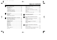
4TP-9-21 7/25/00 3:46 PM Page 5 EAU00009 TABLE OF CONTENTS 1 2 3 SAFETY INFORMATION.....................................1-1 Safe riding.........................................................1-1 Protective apparel .............................................1-3 Modification.......................................................1-3 Loading and accessories ..................................1-3 Gasoline and exhaust gas ................................1-5 Location of important labels ..................
4TP-9-21 7/25/00 3:46 PM Page 6 TABLE OF CONTENTS 1 2 3 4 5 6 7 8 9 Removing and installing panels ........................6-6 Checking the spark plug ...................................6-7 Transmission oil ................................................6-9 Coolant ...........................................................6-10 Changing the coolant ......................................6-12 Cleaning the air filter element .........................6-14 Adjusting the carburetor..........................
4TP-9-21 7/25/00 3:46 PM Page 7 TABLE OF CONTENTS 9 CONSUMER INFORMATION..............................9-1 Identification numbers record ...........................9-1 Key identification number .................................9-1 Vehicle identification number ............................9-1 Model label .......................................................9-2 Motorcycle noise regulation (for Australia) .......
4TP-9-21 7/25/00 3:46 PM Page 8 EAU00017 Q SAFETY INFORMATION 1 2 3 4 5 MOTORCYCLES ARE SINGLE TRACK VEHICLES. THEIR SAFE USE AND OPERATION ARE DEPENDENT UPON THE USE OF PROPER RIDING TECHNIQUES AS WELL AS THE EXPERTISE OF THE OPERATOR. EVERY OPERATOR SHOULD KNOW THE FOLLOWING REQUIREMENTS BEFORE RIDING THIS MOTORCYCLE. HE OR SHE SHOULD: 1. OBTAIN THOROUGH INSTRUCTIONS FROM A COMPETENT SOURCE ON ALL ASPECTS OF MOTORCYCLE OPERATION. 2.
4TP-9-21 7/25/00 3:46 PM Page 9 Q SAFETY INFORMATION 4. Many accidents involve inexperienced operators. In fact, many operators who have been involved in accidents do not even have a current motorcycle license. a. Make sure that you are qualified and that you only lend your motorcycle to other qualified operators. b. Know your skills and limits. Staying within your limits may help you to avoid an accident. c.
4TP-9-21 7/25/00 3:46 PM Page 10 Q SAFETY INFORMATION Protective apparel 1 2 3 4 5 The majority of fatalities from motorcycle accidents are the result of head injuries. The use of a safety helmet is the single most critical factor in the prevention or reduction of head injuries. 1. Always wear an approved helmet. 2. Wear a face shield or goggles. Wind in your unprotected eyes could contribute to an impairment of vision that could delay seeing a hazard. 3.
4TP-9-21 7/25/00 3:46 PM Page 11 Q SAFETY INFORMATION Loading The total weight of the operator, passenger, accessories and cargo must not exceed the maximum load limit of 180 kg. When loading within this weight limit, keep the following in mind: 1. Cargo and accessory weight should be kept as low and close to the motorcycle as possible. Make sure to distribute the weight as evenly as possible on both sides of the motorcycle to minimize imbalance or instability. 2.
4TP-9-21 7/25/00 3:46 PM Page 12 Q SAFETY INFORMATION 1 2 3 4 5 6 7 8 9 1. Never install accessories or carry cargo that would impair the performance of your motorcycle. Carefully inspect the accessory before using it to make sure that it does not in any way reduce ground clearance or cornering clearance, limit suspension travel, steering travel or control operation, or obscure lights or reflectors. a.
4TP-9-21 7/25/00 3:46 PM Page 13 Q SAFETY INFORMATION 2. Never start the engine or let it run for any length of time in a closed area. The exhaust fumes are poisonous and may cause loss of consciousness and death within a short time. Always operate your motorcycle in an area that has adequate ventilation. 3. Always turn the engine off before leaving the motorcycle unattended and remove the key from the main switch. When parking the motorcycle, note the following: a.
4TP-9-21 7/25/00 3:46 PM Page 14 Q SAFETY INFORMATION EAU02977 Location of important labels Please read the following important labels carefully before operating this motorcycle. 1 2 1 1 3 WARNING 4 Before you operate this vehicle, read the owner’s manual.
4TP-9-21 7/25/00 3:46 PM Page 15 1 2 3 4 5 6 7 8 9 1-8
4TP-9-21 7/25/00 3:46 PM Page 16 EAU00026 DESCRIPTION Left view 1 23 4 5 6 7 1 2 3 4 5 6 7 12 8 9 1. Headlight 2. Rear shock absorber compression damping adjusting knob 3. Fuel cock 4. Starter (choke) lever “1” 5. Air filter element 6. 2-stroke engine oil tank 7. Helmet holder 11 (page 6-34) (page 3-14) (page 3-9) (page 3-10) (page 6-14) (page 3-8) (page 3-11) 10 9 8 8. Rear shock absorber spring preload adjusting nut (page 3-13) 9.
4TP-9-21 7/25/00 3:46 PM Page 17 DESCRIPTION Right view 13 14 15 16 17 1 2 3 4 5 6 18 13. 14. 15. 16. 17. 18.
4TP-9-21 7/25/00 3:46 PM Page 18 DESCRIPTION Controls and instruments 1 1 2 3 4 5 6 2 3 4 5 6 7 8 7 8 9 1. 2. 3. 4. 5. Clutch lever Left handlebar switches Speedometer unit Main switch/steering lock Right handlebar switches (page 3-6, 6-20) (page 3-5) (page 3-3) (page 3-1) (page 3-5) 6. Brake lever 7. Throttle grip 8.
4TP-9-21 7/25/00 3:46 PM Page 19 EAU00027 INSTRUMENT AND CONTROL FUNCTIONS ON OFF FF K O N LOC LOCK T IG NI EW000016 Never turn the key to “OFF” or “LOCK” while the motorcycle is moving, otherwise the electrical systems will be switched off, which may result in loss of control or an accident. Make sure that the motorcycle is stopped before turning the key to “OFF” or “LOCK”.
4TP-9-21 7/25/00 3:46 PM Page 20 INSTRUMENT AND CONTROL FUNCTIONS 1 2 3 4 5 1 2 3 4 5 6 6 1. Oil level/coolant temperature warning light “WARNING” 2. Oil level symbol “7” 3. Coolant temperature symbol “ ” 4. Turn signal indicator light “5” 5. High beam indicator light “&” 6. Neutral indicator light “N” EAU03034 Indicator and warning lights 7 EAU03587 8 9 Oil level/coolant temperature warning light “WARNING” This warning light has the following three functions.
4TP-9-21 7/25/00 3:46 PM Page 21 INSTRUMENT AND CONTROL FUNCTIONS 1 2 3 1 4 5 6 6 1. Oil level/coolant temperature warning light “WARNING” 2. Oil level symbol “7” 3. Coolant temperature symbol “ ” 4. Turn signal indicator light “5” 5. High beam indicator light “&” 6. Neutral indicator light “N” EAU00063 High beam indicator light “&” This indicator light comes on when the high beam of the headlight is switched on.
4TP-9-21 7/25/00 3:46 PM Page 22 INSTRUMENT AND CONTROL FUNCTIONS 1 2 3 6 5 4 1 2 3 4 5 6 7 8 9 1. 2. 3. 4. 5. 6. Reset button “RESET” Upper trip odometer Lower trip odometer Digital speedometer Odometer/Clock “ODO/CLOCK” Mode select button “SELECT” NOTE: When the key is turned to “ON”, the speedometer displays “188 km/h” for a few seconds, during which time the electrical circuit is being checked. Mode “A” To set the upper tripmeter to zero, push the reset button for at least one second.
4TP-9-21 7/25/00 3:46 PM Page 23 INSTRUMENT AND CONTROL FUNCTIONS 1 EAU00129 2 1 Horn switch “*” Press this switch to sound the horn. 1 2 3 2 3 1. Dimmer switch 2. Turn signal switch 3. Horn switch “*” 1. Engine stop switch 2. Start switch “,” 4 EAU00138 EAU00118 Engine stop switch Set this switch to “$” to stop the engine in case of an emergency, such as when the motorcycle overturns or when the throttle cable is stuck.
4TP-9-21 7/25/00 3:46 PM Page 24 INSTRUMENT AND CONTROL FUNCTIONS 1 1 6 5 4 3 2 N 1 1 2 3 4 1. Clutch lever EAU00152 5 6 7 8 9 Clutch lever The clutch lever is located at the left handlebar grip. To disengage the clutch, pull the lever toward the handlebar grip. To engage the clutch, release the lever. The lever should be pulled rapidly and released slowly for smooth clutch operation. The clutch lever is equipped with a clutch switch, which is part of the ignition circuit cut-off system.
4TP-9-21 7/25/00 3:46 PM Page 25 INSTRUMENT AND CONTROL FUNCTIONS b 1 a 1 NOTE: The fuel tank cap cannot be installed unless the key is in the lock. In addition, the key cannot be removed if the cap is not properly installed and locked. 1 EW000023 3 w 1. Brake pedal EAU00162 Brake pedal The brake pedal is on the right side of the motorcycle. To apply the rear brake, press down on the brake pedal. 1. Fuel tank cap a. Unlock b. Open EAU00177 Fuel tank cap To remove the fuel tank cap 1.
4TP-9-21 7/25/00 3:46 PM Page 26 INSTRUMENT AND CONTROL FUNCTIONS 1 EAU00185 cC 2 Immediately wipe off spilled fuel with a clean, dry, soft cloth, since fuel may deteriorate painted surfaces or plastic parts. 1 2 3 4 6 7 8 9 2 EAU00192 1. Filler tube 2. Fuel level EAU01183 5 1 Fuel Make sure that there is sufficient fuel in the tank. Fill the fuel tank to the bottom of the filler tube as shown in the illustration.
4TP-9-21 7/25/00 3:46 PM Page 27 INSTRUMENT AND CONTROL FUNCTIONS NOTE: Make sure that the 2-stroke engine oil tank cap is properly closed. OFF: Closed position ON: Normal position RES RES OFF Recommended oil: Yamalube 2 or equivalent 2-stroke engine oil (JASO grade “FC”) Oil quantity: 1.3 L 1 OFF ON FUEL ON 1 ON 1. Arrow mark positioned over “OFF” 2 FUEL 1 1.
4TP-9-21 7/25/00 3:46 PM Page 28 INSTRUMENT AND CONTROL FUNCTIONS RES: Reserve position RES 1 2 3 4 5 6 7 8 a RES 1 OFF ON FUEL 1 1. Arrow mark positioned over “RES” RES This indicates reserve. If you run out of fuel while riding, move the lever to this position. Fill the tank at the first opportunity. Be sure to set the lever back to “ON” after refueling! b 1 1. Starter (choke) lever “1” 1.
4TP-9-21 7/25/00 3:46 PM Page 29 INSTRUMENT AND CONTROL FUNCTIONS EAU03589 1 Adjusting the front fork 1 This front fork is equipped with damping force adjusting screws. a w Always adjust both fork legs equally, otherwise poor handling and loss of stability may result. 2 1. Projection (×2) 2. Seat holder (×2) To install the seat 1. Insert the projections on the front of the seat into the seat holders as shown. 2. Place the seat in the original position, and then tighten the bolts.
4TP-9-21 7/25/00 3:46 PM Page 30 INSTRUMENT AND CONTROL FUNCTIONS 1 1 4 5 6 7 8 9 17 clicks in direction b* Standard 14 clicks in direction b* Maximum (hard) 1 click in direction b* * With the adjusting screw fully turned in direction a 2 3 Minimum (soft) a b 1. Compression damping adjusting screw Adjust the damping force as follows. 1. Remove the rubber cap from the bottom of each fork leg. 2.
4TP-9-21 7/25/00 3:46 PM Page 31 INSTRUMENT AND CONTROL FUNCTIONS a 1 1 b 1. Special wrench Spring preload 1. Loosen the locknut. 2. To increase the spring preload and thereby harden the suspension, turn the adjusting nut in direction a. To decrease the spring preload and thereby soften the suspension, turn the adjusting nut in direction b. a 2 Spring preload: Minimum (soft): Distance A = 252 mm Standard: Distance A = 244 mm Maximum (hard): Distance A = 234 mm 1 2 3 3.
4TP-9-21 7/25/00 3:46 PM Page 32 INSTRUMENT AND CONTROL FUNCTIONS 1 2 1 1 a b a b 3 4 5 6 7 1. Adjusting dial 1. Adjusting knob Rebound damping force To increase the rebound damping force and thereby harden the rebound damping, turn the adjusting dial in direction a. To decrease the rebound damping force and thereby soften the rebound damping, turn the adjusting dial in direction b.
4TP-9-21 7/25/00 3:46 PM Page 33 INSTRUMENT AND CONTROL FUNCTIONS w EW000041 This shock absorber contains highly pressurized nitrogen gas. For proper handling, read and understand the following information before handling the shock absorber. The manufacturer cannot be held responsible for property damage or personal injury that may result from improper handling. 8 Do not tamper with or attempt to open the gas cylinder.
4TP-9-21 7/25/00 3:46 PM Page 34 INSTRUMENT AND CONTROL FUNCTIONS EAU00330 Sidestand 1 2 3 4 5 6 7 The sidestand is located on the left side of the frame. Raise the sidestand or lower it with your foot while holding the motorcycle upright. NOTE: The built-in sidestand switch is part of the ignition circuit cut-off system, which cuts the ignition in certain situations. (See further down for an explanation of the ignition circuit cutoff system.
4TP-9-21 7/25/00 3:46 PM Page 35 INSTRUMENT AND CONTROL FUNCTIONS NOTE: This check is most reliable if performed with a warmed-up engine. With the engine turned off: 1. Move the sidestand down. 2. Make sure that the engine stop switch is set to “#”. 3. Turn the key to “ON”. 4. Shift the transmission into the neutral position. 5. Push the start switch. Does the engine start? YES 2 The neutral switch may be defective. The motorcycle should not be ridden until checked by a Yamaha dealer.
4TP-9-21 7/25/00 3:46 PM Page 36 EAU01114 PRE-OPERATION CHECKS 1 The condition of a vehicle is the owner’s responsibility. Vital components can start to deteriorate quickly and unexpectedly, even if the vehicle remains unused (for example, as a result of exposure to the elements). Any damage, fluid leakage or loss of tire air pressure could have serious consequences. Therefore, it is very important, in addition to a thorough visual inspection, to check the following points before each ride.
4TP-9-21 7/25/00 3:46 PM Page 37 PRE-OPERATION CHECKS ITEM CHECKS PAGE Clutch • • • • Check operation. Lubricate cable if necessary. Check lever free play. Adjust if necessary. 3-6, 6-20–6-21 Throttle grip • • • • Make sure that operation is smooth. Lubricate throttle grip, housing and cable if necessary. Check free play. Adjust if necessary. 6-16–6-17, 6-28 Control cables • Make sure that operation is smooth. • Lubricate if necessary. Drive chain • • • • Check chain slack.
4TP-9-21 7/25/00 3:46 PM Page 38 PRE-OPERATION CHECKS ITEM 1 2 3 4 5 6 CHECKS Chassis fasteners • Make sure that all nuts, bolts and screws are properly tightened. • Tighten if necessary. Instruments, lights, signals and switches • Check operation. • Correct if necessary. Sidestand switch • Check operation of ignition circuit cut-off system. • If system is defective, have Yamaha dealer check vehicle.
4TP-9-21 7/25/00 3:46 PM Page 39 EAU00372 OPERATION AND IMPORTANT RIDING POINTS w EAU00373 8 Become thoroughly familiar with all operating controls and their functions before riding. Consult a Yamaha dealer regarding any control or function that you do not thoroughly understand. 8 Never start the engine or operate it in a closed area for any length of time. Exhaust fumes are poisonous, and inhaling them can cause loss of consciousness and death within a short time.
4TP-9-21 7/25/00 3:46 PM Page 40 OPERATION AND IMPORTANT RIDING POINTS 1 2 3 4 5 6 7 8 9 NOTE: If the engine fails to start, release the start switch, wait a few seconds, and then try again. Each starting attempt should be as short as possible to preserve the battery. Do not crank the engine more than 10 seconds on any one attempt.
4TP-9-21 7/25/00 3:46 PM Page 41 OPERATION AND IMPORTANT RIDING POINTS cC EC000048 8 Even with the transmission in the neutral position, do not coast for long periods of time with the engine off, and do not tow the motorcycle for long distances. The transmission is properly lubricated only when the engine is running. Inadequate lubrication may damage the transmission.
4TP-9-21 7/25/00 3:46 PM Page 42 OPERATION AND IMPORTANT RIDING POINTS EAU00455 1 2 3 4 5 6 7 8 9 0–150 km 8 Avoid prolonged operation above 1/3 throttle. 8 After every hour of operation, stop the engine, and then let it cool for five to ten minutes. 8 Vary the engine speed from time to time. Do not operate the engine at one set throttle position. 1,000 km and beyond Avoid prolonged full-throttle operation. Vary the engine speed occasionally.
4TP-9-21 7/25/00 3:46 PM Page 43 EAU00462 PERIODIC MAINTENANCE AND MINOR REPAIR EAU00464 Safety is an obligation of the owner. Periodic inspection, adjustment and lubrication will keep your vehicle in the safest and most efficient condition possible. The most important points of inspection, adjustment, and lubrication are explained on the following pages. The intervals given in the periodic maintenance and lubrication chart should be simply considered as a general guide under normal riding conditions.
4TP-9-21 7/25/00 3:46 PM Page 44 PERIODIC MAINTENANCE AND MINOR REPAIR EAU03540 Periodic maintenance and lubrication chart 1 2 NOTE: 8 The annual checks must be performed every year, except if a kilometer-based maintenance is performed instead. 8 From 30,000 km, repeat the maintenance intervals starting from 6,000 km. 8 Items marked with an asterisk should be performed by a Yamaha dealer as they require special tools, data and technical skills. 3 4 NO.
4TP-9-21 7/25/00 3:46 PM Page 45 PERIODIC MAINTENANCE AND MINOR REPAIR NO. 9 10 11 ITEM CHECK OR MAINTENANCE JOB ODOMETER READING (×1,000 km) 1 6 12 18 24 ANNUAL CHECK * Tires • Check tread depth and for damage. • Replace if necessary. • Check air pressure. • Correct if necessary. √ √ √ √ 1 * * Wheel bearings • Check bearing for looseness or damage. √ √ √ √ 2 Swingarm • Check operation and for excessive play. √ √ √ √ 12 Drive chain • Check chain slack.
4TP-9-21 7/25/00 3:46 PM Page 46 PERIODIC MAINTENANCE AND MINOR REPAIR NO. 1 2 3 4 22 • Check oil level and vehicle for leakage. • Change. • Check coolant level and vehicle for coolant leakage. • Change. ODOMETER READING (×1,000 km) 1 6 12 18 24 √ √ √ √ √ √ √ √ √ √ √ Every 3 years • Check operation. √ ITEM Transmission oil 23 * Cooling system 24 * Front and rear brake switches CHECK OR MAINTENANCE JOB 25 Moving parts and cables • Lubricate.
4TP-9-21 7/25/00 3:46 PM Page 47 PERIODIC MAINTENANCE AND MINOR REPAIR 2 1 1 1 1 2 3 1. Cowling A 2. Cowling B 1. Screw (×4) 1. Screw (×3) EAU00484 EAU01065 Removing and installing cowlings The cowlings shown above need to be removed to perform some of the maintenance jobs described in this chapter. Refer to this section each time a cowling needs to be removed and installed. 4 EAU00482 Cowling A To remove the cowling Remove the cowling screws, and then pull the cowling off as shown.
4TP-9-21 7/25/00 3:46 PM Page 48 PERIODIC MAINTENANCE AND MINOR REPAIR 1 1 1 1 2 3 4 1. Panel A 1. Panel B EAU01122 5 6 7 Removing and installing panels The panels shown above need to be removed to perform some of the maintenance jobs described in this chapter. 1. Screw Refer to this section each time a panel needs to be removed and installed. EAU00488 Panel A To remove the panel Remove the screw, and then pull the panel off as shown.
4TP-9-21 7/25/00 3:46 PM Page 49 PERIODIC MAINTENANCE AND MINOR REPAIR 1 1 1 1. Screw 1. Spark plug cap 1. Spark plug wrench EAU00488 Panel B To remove the panel Remove the screw, and then pull the panel off as shown. To install the panel Place the panel in the original position, and then install the screw. EAU01833 Checking the spark plug The spark plug is an important engine component, which is easy to check.
4TP-9-21 7/25/00 3:46 PM Page 50 PERIODIC MAINTENANCE AND MINOR REPAIR 1 2 3 4 5 To check the spark plug 1. Check that the porcelain insulator around the center electrode of the spark plug is a medium-tolight tan (the ideal color when the motorcycle is ridden normally). NOTE: If the spark plug shows a distinctly different color, the engine could be defective. Do not attempt to diagnose such problems yourself. Instead, have a Yamaha dealer check the motorcycle. 6 7 8 9 2.
4TP-9-21 7/25/00 3:46 PM Page 51 PERIODIC MAINTENANCE AND MINOR REPAIR EAU03109 Transmission oil 2 Oil level inspection 1. Place the motorcycle on a level place and hold it in an upright position. Warm up the engine for several minutes. 3 NOTE: Be sure the motorcycle is positioned straight up when checking the oil level. A slight tilt toward the side can result in false readings. 1 1 1 2 3 1. Oil level window 2. Maximum level 3. Minimum level 1. Oil filler cap 2.
4TP-9-21 7/25/00 3:46 PM Page 52 PERIODIC MAINTENANCE AND MINOR REPAIR EAU01808 1 1 2 5 6 7 8 9 1. Drain bolt 3. Remove the drain bolt and drain the oil. 4. Install the drain bolt and tighten it to the specified torque. Tightening torque: Drain bolt: 15 Nm (1.5 m0kg) 5. Fill the engine with sufficient oil to reach the specified level. Install the oil filler cap and tighten it. Coolant To check the coolant level 1. Place the motorcycle on a level surface and hold it in an upright position.
4TP-9-21 7/25/00 3:46 PM Page 53 PERIODIC MAINTENANCE AND MINOR REPAIR 3 1 2 1. Maximum level mark 2. Minimum level mark 3. Coolant reservoir 2. Remove panel B. (See page 6-7 for panel removal and installation procedures.) 3. Check the coolant level in the coolant reservoir. NOTE: The coolant should be between the minimum and maximum level marks. 4. If the coolant is at or below the minimum level mark, open the reservoir cap, add coolant to the maximum level mark, and then close the reservoir cap.
4TP-9-21 7/25/00 3:46 PM Page 54 PERIODIC MAINTENANCE AND MINOR REPAIR 2 1 1 1 2 2 1 3 3 4 1. Radiator cap stopper bolt 2. Radiator cap 5 Changing the coolant 1. Coolant drain bolt EAU03101 6 7 8 1. Put the motorcycle on a level place. 2. Remove cowling B and panel B. (See pages 6-5 and 6-7 for cowling and panel removal and installation procedures.) 3. Remove the radiator cap stopper bolt and the radiator cap. 4. Place a container under the engine and remove the coolant drain bolt. 9 1.
4TP-9-21 7/25/00 3:46 PM Page 55 PERIODIC MAINTENANCE AND MINOR REPAIR 8. Install the reservoir tank hose. 9. Pour the recommended coolant into the radiator until it is full. Recommended antifreeze: High quality ethylene glycol antifreeze containing corrosion inhibitors for aluminum engines. Antifreeze and water mixing ratio: 1:1 Total amount: 1.26 L Reservoir tank capacity: 0.36 L EC000080 cC 8 If coolant is not available, use distilled water or soft tap water instead.
4TP-9-21 7/25/00 3:46 PM Page 56 PERIODIC MAINTENANCE AND MINOR REPAIR 1 2 3 4 1 2 1 2 3 4 1. Screw (×3) 2. Air filter case cover 5 Cleaning the air filter element EAU03671 6 7 8 9 3. Pull the air filter element out from the air filter case. 1. 2. 3. 4. Air filter element guide Air filter element frame Sponge material Wing nut 4. Remove the wing nut , and then pull the air filter element off of the guide. 5. Remove the sponge material from the air filter element frame.
4TP-9-21 7/25/00 3:46 PM Page 57 PERIODIC MAINTENANCE AND MINOR REPAIR 1 3 2 4 8. Install the sponge material onto the frame, place the air filter element in the original position on the guide, and then tighten the wing nut. 9. Insert the air filter element into the air filter case. EC000082 cC 6. Clean the sponge material with solvent, and then squeeze the remaining solvent out. 7. Apply oil of the recommended type to the entire surface of the sponge material, and then squeeze the excess oil out.
4TP-9-21 7/25/00 3:46 PM Page 58 PERIODIC MAINTENANCE AND MINOR REPAIR EAU01168 1 Adjusting the engine idling speed 1 2 3 4 The engine idling speed must be checked and, if necessary, adjusted as follows at the intervals specified in the periodic maintenance and lubrication chart. NOTE: A diagnostic tachometer is needed to make this adjustment. 5 6 7 8 9 1. Attach the tachometer to the spark plug lead. 2.
4TP-9-21 7/25/00 3:46 PM Page 59 PERIODIC MAINTENANCE AND MINOR REPAIR EAU03593 1 Tire air pressure (measured on cold tires) Tires 2 To maximize the performance, durability, and safe operation of your motorcycle, note the following points regarding the specified tires. b a 1. Adjusting nut 2. Locknut 1. Loosen the locknut. 2. To increase the throttle cable free play, turn the adjusting nut in direction a. To decrease the throttle cable free play, turn the adjusting nut in direction b. 3.
4TP-9-21 7/25/00 3:46 PM Page 60 PERIODIC MAINTENANCE AND MINOR REPAIR w 1 2 3 4 5 6 7 8 9 EWA00012 Because loading has an enormous impact on the handling, braking, performance and safety characteristics of your motorcycle, you should keep the following precautions in mind. 8 NEVER OVERLOAD THE MOTORCYCLE! Operation of an overloaded motorcycle may result in tire damage, loss of control, or severe injury.
4TP-9-21 7/25/00 3:46 PM Page 61 PERIODIC MAINTENANCE AND MINOR REPAIR w EW000079 8 Have a Yamaha dealer replace excessively worn tires. Besides being illegal, operating the motorcycle with excessively worn tires decreases riding stability and can lead to loss of control. 8 The replacement of all wheeland brake-related parts, including the tires, should be left to a Yamaha dealer, who has the necessary professional knowledge and experience. Tire information This motorcycle is equipped with tube tires.
4TP-9-21 7/25/00 3:46 PM Page 62 PERIODIC MAINTENANCE AND MINOR REPAIR EAU00685 Spoke wheels 1 2 3 4 5 6 7 8 9 To maximize the performance, durability, and safe operation of your motorcycle, note the following points regarding the specified wheels. 8 The wheel rims should be checked for cracks, bends or warpage, and the spokes for looseness or damage before each ride. If any damage is found, have a Yamaha dealer replace the wheel. Do not attempt even the smallest repair to the wheel.
4TP-9-21 7/25/00 3:46 PM Page 63 PERIODIC MAINTENANCE AND MINOR REPAIR 1 2 a b 1. 2. 3. 4. 3 4 a b Locknut (Clutch lever) Adjusting bolt Locknut (Clutch cable) Adjusting nut 4. Fully turn the adjusting bolt in direction a to loosen the clutch cable. 5. Loosen the locknut further down the clutch cable. 6. To increase the clutch lever free play, turn the adjusting nut in direction a. To decrease the clutch lever free play, turn the adjusting nut in direction b. 7. Tighten both locknuts.
4TP-9-21 7/25/00 3:46 PM Page 64 PERIODIC MAINTENANCE AND MINOR REPAIR w 1 2 3 4 5 6 7 8 EW000099 8 After adjusting the brake lever free play, check the free play and make sure that the brake is working properly. 8 A soft or spongy feeling in the brake lever can indicate the presence of air in the hydraulic system. If there is air in the hydraulic system, have a Yamaha dealer bleed the system before operating the motorcycle.
4TP-9-21 7/25/00 3:46 PM Page 65 PERIODIC MAINTENANCE AND MINOR REPAIR FRONT 1 REAR 1 1 1 2 a 2 b 3 1. Brake light switch 2. Adjusting nut 1. Indicator groove 1. Indicator groove EAU01314 EAU00713 Adjusting the rear brake light switch The rear brake light switch, which is activated by the brake pedal, is properly adjusted when the brake light comes on just before braking takes effect. If necessary, adjust the brake light switch as follows.
4TP-9-21 7/25/00 3:46 PM Page 66 PERIODIC MAINTENANCE AND MINOR REPAIR FRONT REAR 1 1 1 2 3 4 1. Minimum level mark 1. Minimum level mark EAU03196 5 6 7 8 9 Checking the brake fluid level Insufficient brake fluid may allow air to enter the brake system, possibly causing it to become ineffective. Before riding, check that the brake fluid is above the minimum level mark and replenish if necessary. A low brake fluid level may indicate worn brake pads and/or brake system leakage.
4TP-9-21 7/25/00 3:46 PM Page 67 PERIODIC MAINTENANCE AND MINOR REPAIR EAU03073 EAU00744 Changing the brake fluid Drive chain slack Have a Yamaha dealer change the brake fluid at the intervals specified in the periodic maintenance and lubrication chart. In addition, have the oil seals of the master cylinder and caliper as well as the brake hoses replaced at the intervals listed below or whenever they are damaged or leaking. 8 Oil seals: Replace every two years.
4TP-9-21 7/25/00 3:46 PM Page 68 PERIODIC MAINTENANCE AND MINOR REPAIR 1 a b 2 3 4 1. Axle nut 2. Chain adjusting plate EAU03594 5 6 7 8 9 To adjust the drive chain slack 1. Loosen the axle nut. 2. To tighten the drive chain, turn the adjusting plate on each side of the swingarm in direction a. To loosen the drive chain, turn the adjusting plate on each side of the swingarm in direction b, and then push the rear wheel forward.
4TP-9-21 7/25/00 3:46 PM Page 69 PERIODIC MAINTENANCE AND MINOR REPAIR 3. Thoroughly lubricate the drive chain with a special O-ring chain lubricant. cC w EW000112 Damage to the outer sheath may interfere with proper cable operation and will cause the inner cable to rust. Replace a damaged cable as soon as possible to prevent unsafe conditions. ECA00052 Do not use engine oil or any other lubricants for the drive chain, as they may contain substances that could damage the O-rings.
4TP-9-21 7/25/00 3:46 PM Page 70 PERIODIC MAINTENANCE AND MINOR REPAIR EAU03209 Checking and lubricating the throttle grip and cable 1 2 3 4 5 6 7 8 9 The operation of the throttle grip and the condition of the throttle cable should be checked before each ride, and the cable should be lubricated or replaced if necessary. NOTE: Since the throttle grip must be removed to access the throttle cable end, the throttle grip and the cable should always be lubricated at the same time. 4.
4TP-9-21 7/25/00 3:46 PM Page 71 PERIODIC MAINTENANCE AND MINOR REPAIR 1 2 3 4 EAU03370 EAU03164 EAU03165 Checking and lubricating the brake and shift pedals Checking and lubricating the brake and clutch levers Checking and lubricating the sidestand The operation of the brake and shift pedals should be checked before each ride, and the pedal pivots should be lubricated if necessary.
4TP-9-21 7/25/00 3:46 PM Page 72 PERIODIC MAINTENANCE AND MINOR REPAIR EAU02939 1 Checking the front fork The condition and operation of the front fork must be checked as follows at the intervals specified in the periodic maintenance and lubrication chart. 1 2 3 To check the condition 4 1. Grease nipple (×2) EAU00790 5 6 7 8 Lubricating the rear suspension The pivoting points of the rear suspension must be lubricated at the intervals specified in the periodic maintenance and lubrication chart.
4TP-9-21 7/25/00 3:46 PM Page 73 PERIODIC MAINTENANCE AND MINOR REPAIR EAU00794 EAU01144 Checking the steering Checking the wheel bearings Worn or loose steering bearings may cause danger. Therefore, the operation of the steering must be checked as follows at the intervals specified in the periodic maintenance and lubrication chart. 1. Place a stand under the engine to raise the front wheel off the ground.
4TP-9-21 7/25/00 3:46 PM Page 74 PERIODIC MAINTENANCE AND MINOR REPAIR 1 2 3 4 5 6 7 1. Battery EAU00800 Battery This motorcycle is equipped with a sealed-type (MF) battery, which does not require any maintenance. There is no need to check the electrolyte or to add distilled water. EC000101 8 cC 9 EW000116 w 1 Never attempt to remove the battery cell seals, as this would permanently damage the battery.
4TP-9-21 7/25/00 3:46 PM Page 75 PERIODIC MAINTENANCE AND MINOR REPAIR To store the battery 1. If the motorcycle will not be used for more than one month, remove the battery, fully charge it, and then place it in a cool, dry place. 2. If the battery will be stored for more than two months, check it at least once a month and fully charge it if necessary. 3. Fully charge the battery before installation. 4. After installation, make sure that the battery leads are properly connected to the battery terminals.
4TP-9-21 7/25/00 3:46 PM Page 76 PERIODIC MAINTENANCE AND MINOR REPAIR cC 1 2 EC000103 Do not use a fuse of a higher amperage rating than recommended to avoid causing extensive damage to the electrical system and possibly a fire. 3 4 5 6 3. Turn the key to “ON” and turn on the electrical circuits to check if the devices operate. 4. If the fuse immediately blows again, have a Yamaha dealer check the electrical system.
4TP-9-21 7/25/00 3:46 PM Page 77 PERIODIC MAINTENANCE AND MINOR REPAIR 1 1 a 1 2 3 1. Headlight bulb cover 1. Headlight bulb holder a. Do not touch this area 3. Unhook the headlight bulb holder, and then remove the defective bulb. EW000119 w Headlight bulbs get very hot. Therefore, keep flammable products away from a lit headlight bulb, and do not touch the bulb until it has cooled down. 4. Put a new bulb into position, and then secure it with the bulb holder.
4TP-9-21 7/25/00 3:46 PM Page 78 PERIODIC MAINTENANCE AND MINOR REPAIR 1 6. Install the cowling together with the headlight unit. 7. Have a Yamaha dealer adjust the headlight beam if necessary. 1 2 1 2 3 4 1. Screw 2. Lens 1. Bulb 5 Replacing a turn signal light bulb EAU03497 6 1. Remove the turn signal light lens by removing the screw. 7 8 2. Remove the defective bulb by pushing it in and turning it counterclockwise. 3.
4TP-9-21 7/25/00 3:46 PM Page 79 PERIODIC MAINTENANCE AND MINOR REPAIR 1 1 1 2 2 1 3 1. Screw (×2) 2. Lens 1. Bulb EAU01623 Replacing the tail/brake light bulb 1. Remove the tail/brake light lens by removing the screws. 1. Nut (×2) 2. Remove the defective bulb by pushing it in and turning it counterclockwise. 3. Insert a new bulb into the socket, push it in, and then turn it clockwise until it stops. 4. Install the lens by installing the screws.
4TP-9-21 7/25/00 3:46 PM Page 80 PERIODIC MAINTENANCE AND MINOR REPAIR EAU01579 1 1 2 1 3 4 5 6 7 1. Nut (×2) 2. Remove the license plate light lens by removing the nuts. 1. Bulb (×2) 3. Remove the defective bulb by pulling it out. 4. Insert a new bulb into the socket. 5. Install the lens by installing the nuts. 6. Install the license plate light by installing the nuts.
4TP-9-21 7/25/00 3:46 PM Page 81 PERIODIC MAINTENANCE AND MINOR REPAIR To service the rear wheel Raise the rear wheel off the ground by using a motorcycle stand or, if a motorcycle stand is not available, by placing a jack either under each side of the frame in front of the rear wheel or under each side of the swingarm. 3. Pull the wheel axle out, and then remove the wheel.
4TP-9-21 7/25/00 3:46 PM Page 82 PERIODIC MAINTENANCE AND MINOR REPAIR EAU03678 1 To install the front wheel 1. Lift the wheel up between the fork legs and guide the brake disc between the brake pads. 2 3 4 5 6 7 8 9 NOTE: Make sure that there is enough space between the brake pads before inserting the brake disc. 2. Insert the wheel axle. 3. Lower the front wheel so that it is on the ground. 4. Tighten the wheel axle to the specified torque.
4TP-9-21 7/25/00 3:46 PM Page 83 PERIODIC MAINTENANCE AND MINOR REPAIR EAU01806 To install the rear wheel 1. Install the drive chain onto the rear sprocket, and then insert the wheel axle from the left side. 1 1 2 1. Swingarm end bolt (×2) 3. Remove the swingarm end bolt from each end of the swingarm. 4. Push the wheel forward, and then remove the drive chain from the rear sprocket. NOTE: The drive chain does not need to be disassembled in order to remove and install the rear wheel. 5.
4TP-9-21 7/25/00 3:46 PM Page 84 PERIODIC MAINTENANCE AND MINOR REPAIR EAU03087 Troubleshooting 1 2 3 4 5 6 7 8 9 Although Yamaha motorcycles receive a thorough inspection before shipment from the factory, trouble may occur during operation. Any problem in the fuel, compression, or ignition systems, for example, can cause poor starting and loss of power. The following troubleshooting charts represent quick and easy procedures for checking these vital systems yourself.
4TP-9-21 7/25/00 3:46 PM Page 85 PERIODIC MAINTENANCE AND MINOR REPAIR EAU01581 Troubleshooting charts Starting problems or poor engine performance EW000125 w 1 Keep away open flames and do not smoke while checking or working on the fuel system. 2 1. Fuel 3 Enough fuel. Go to compression check. No fuel. Supply fuel. Check if there is fuel in the fuel tank. 2. Compression 4 Engine doesn’t start, go to compression check. 5 There is compression. Go to ignition check. No compression.
4TP-9-21 7/25/00 3:46 PM Page 86 PERIODIC MAINTENANCE AND MINOR REPAIR Engine overheating EW000070 w 1 2 3 8 Do not remove the radiator cap when the engine and radiator are hot. Scalding hot fluid and steam may be blown out under pressure, which could cause serious injury. Be sure to wait until the engine has cooled.
4TP-9-21 7/25/00 3:46 PM Page 87 EAU03521 MOTORCYCLE CARE AND STORAGE Care While the open design of a motorcycle reveals the attractiveness of the technology, it also makes it more vulnerable. Rust and corrosion can develop even if high-quality components are used. A rusty exhaust pipe may go unnoticed on a car, however, it detracts from the overall appearance of a motorcycle.
4TP-9-21 7/25/00 3:46 PM Page 88 MOTORCYCLE CARE AND STORAGE 1 2 3 4 5 6 7 8 9 8 Do not use any harsh chemical products on plastic parts. Be sure to avoid using cloths or sponges which have been in contact with strong or abrasive cleaning products, solvent or thinner, fuel (gasoline), rust removers or inhibitors, brake fluid, antifreeze or electrolyte.
4TP-9-21 7/25/00 3:46 PM Page 89 MOTORCYCLE CARE AND STORAGE After cleaning 1. Dry the motorcycle with a chamois or an absorbing cloth. 2. Immediately dry the drive chain and lubricate it to prevent it from rusting. 3. Use a chrome polish to shine chrome, aluminum and stainlesssteel parts, including the exhaust system. (Even the thermally induced discoloring of stainlesssteel exhaust systems can be removed through polishing.) 4.
4TP-9-21 7/25/00 3:46 PM Page 90 MOTORCYCLE CARE AND STORAGE Storage 2 Short-term Always store your motorcycle in a cool, dry place and, if necessary, protect it against dust with a porous cover. 3 cC 1 4 5 6 7 8 9 ECA00014 8 Storing the motorcycle in a poorly ventilated room or covering it with a tarp, while it is still wet, will allow water and humidity to seep in and cause rust.
4TP-9-21 7/25/00 3:46 PM Page 91 MOTORCYCLE CARE AND STORAGE 6. Lubricate all control cables and the pivoting points of all levers and pedals as well as of the sidestand/centerstand. 7. Check and, if necessary, correct the tire air pressure, and then lift the motorcycle so that both of its wheels are off the ground. Alternatively, turn the wheels a little every month in order to prevent the tires from becoming degraded in one spot. 8.
4TP-9-21 7/25/00 3:46 PM Page 92 EAU01038 SPECIFICATIONS Specifications 1 2 3 4 5 6 Model Engine oil DT230(N) Type Dimensions Overall length Overall width Overall height 1,410 mm Minimum turning radius 1.3 L Transmission oil 1,200 mm Wheel base Basic weight (with oil and full fuel tank) Total amount 800 mm 865 mm Ground clearance Capacity 2,225 mm Seat height 2-stroke engine oil Type SAE 10W30 type SE motor oil Capacity 300 mm 2,100 mm Periodic oil change 0.
4TP-9-21 7/25/00 3:46 PM Page 93 SPECIFICATIONS Spark plug Tires Manufacturer/model NGK/BR9ES Type Gap 0.7–0.8 mm Front Clutch type Wet, multiple-disc Transmission Primary reduction system Helical gear Primary reduction ratio 54/21 (2.571) Secondary reduction system Chain drive Secondary reduction ratio 3.437 Number of drive chain sprocket teeth (rear/front) 55/16 Transmission type Constant mesh 6-speed Operation Gear ratio 3.
4TP-9-21 7/25/00 3:46 PM Page 94 SPECIFICATIONS 1 Front 2 3 4 5 Type Spoke wheel Size 1.60 × 21 Type Spoke wheel Size 2.15 × 18 Rear Coil-gas spring/oil damper Front 250 mm Rear 240 mm Ignition system C.D.I. Charging system Front Type C.D.I.
4TP-9-21 7/25/00 3:46 PM Page 95 SPECIFICATIONS Neutral indicator light 12 V, 3W × 1 High beam indicator light 12 V, 3W × 1 Turn signal indicator light 12 V, 3W × 1 Oil level/coolant temperature warning light LED Fuse 1 2 3 30A 4 5 6 7 8 9 8-4
4TP-9-21 7/25/00 3:46 PM Page 96 SPECIFICATIONS EAU01064 Conversion table CONVERSION TABLE 2 All specification data in this manual are listed in SI and METRIC UNITS. Use this table to convert METRIC unit data to IMPERIAL unit data. 3 Ex. 1 METRIC TO IMPERIAL Metric unit Multiplier Imperial unit Torque m • kg m • kg cm • kg cm • kg 7.233 86.794 0.0723 0.8679 ft • lb in• lb ft • lb in • lb Weight kg g 2.205 0.03527 lb oz Speed km/hr 0.6214 mph Distance km m m cm mm 0.6214 3.281 1.
4TP-9-21 7/25/00 3:46 PM Page 97 EAU01039 CONSUMER INFORMATION EAU02944 Identification numbers Record the key identification number, vehicle identification number and model label information in the spaces provided below for assistance when ordering spare parts from a Yamaha dealer or for reference in case the vehicle is stolen. 1. KEY IDENTIFICATION NUMBER: 2. VEHICLE IDENTIFICATION NUMBER: 1 1 2 1 3 1. Key identification number 1.
4TP-9-21 7/25/00 3:46 PM Page 98 CONSUMER INFORMATION EAU01388 Motorcycle noise regulation (for Australia) 1 1 2 3 4 1. Model label EAU01049 5 6 7 8 9 Model label The model label is affixed to the location shown in the figure. Record the information on this label in the space provided. This information will be needed when ordering spare parts from a Yamaha dealer.
4TP-9-21 7/25/00 3:46 PM Page 99 1 2 3 4 5 6 7 8 9
4TP-9-21 7/25/00 3:46 PM Page 100
OWNER’S MANUAL DT230(N) YAMAHA MOTOR CO., LTD. PRINTED ON RECYCLED PAPER PRINTED IN JAPAN 2000·7–0.