
Owner's Manual

16
DTX900 Owner’s Manual
Setting Up
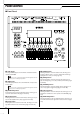
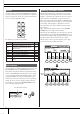
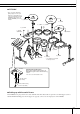
Connecting the Pads
Referring to the illustration below, connect the output cable from each pad to each Trigger Input jack located on the rear
panel of the DTX900. All Trigger Input jacks are conveniently labeled (1 SNARE, etc.), so make sure each pad is connected
to its corresponding Trigger Input jack.
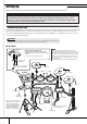
■ DTX900K
IMPORTANT
You’ll need to change the Trigger Settings of the DTX900 according to the type of drum set you are using (Stan-
dard Set/Special Set/Acoustic Drums, etc.). If the setting is not appropriate, problems may occur—such as
improper sound, or inappropriate volume balance among the pads. Refer to the “Selecting the Trigger Setup”
section on page 22 on how to select the appropriate setup.
•To prevent electric shock and damage to the devices, make sure the power is switched OFF on the DTX900 and all
related devices before making any connections to the DTX900’s input and output jacks.
WARNING
PCY135
DTX900
PCY155
PCY135
KP125W
XP120SD
RHH135
XP100T XP100T
XP100T
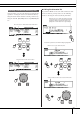
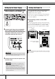
Attaching the module stand
Attach the included module stand to the
DTX900 using the module stand fastening
screws.
* Be sure to use the included screws.
to 1SNARE
to JKICK/K
to 2TOM1 to 3TOM2
to 4TOM3
to HI-HAT
CONTROL
to 9HI-HAT
to 7CRASH
to 6RIDE
DTX900
Module stand
(included)
Module stand fastening
screws x 4 (included)
* First, connect the RHH135’s
[PAD] output jack to the 9HI-
HAT jack on the DTX900,
then connect the RHH135’s
[HI-HAT CONTROL] output
jack to the HI-HAT CON-
TROL jack on the DTX900.
*Foot pedal is not included
in the Standard Set.
NOTE
• The pad models described in the illustrations were
included in the Standard Set/Special Set at the moment
this Owner’s Manual was produced. Keep in mind that the
model names of your Standard Set or Special Set may be
different from the ones illustrated here. For details about
the latest information on Yamaha drum pads, refer to the
following website.
http://www.yamaha.co.jp/english/product/drums/ed/
to 8CRASH2