
User Manual


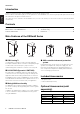


Table Of Contents

DXRmkII series Owner’s Manual 7
Controls and Functions
English
Controls and Functions
Rear panel
1
INPUT jacks
These comprise a balanced XLR input jack (INPUT 1),
unbalanced phones (INPUT 2) and RCA pin input jacks
(INPUT 3).
You can connect a mixing console or microphone to
INPUT 1, a keyboard or electric-acoustic guitar to INPUT 2,
and a portable audio player or CD player to INPUT 3. Signals
from INPUT 1-3 are mixed inside the DXRmkII unit.
2
THRU jack
This is a balanced XLR output jack. The INPUT 1 signal is
passed through unaffected, since this is parallel-connected
to the INPUT 1 (XLR) jack.
3
LEVEL controls
For adjusting the level of each INPUT signal. If you connect a
device that features a nominal output level of +4dBu (such as
a mixing console), set the MIC/LINE switch (9) on the
DXRmkII series to LINE, and adjust the LEVEL control using
its 12 o’clock position as a reference.
4
LIMIT indicator
Lights when the output limiter is active. The output limiter will
operate in order to protect the speaker and amp, attenuating
the output signal to the amplifier. If this indicator stays lit,
lower the level of the input signal.
NOTE
• If the output voltage of the amplifier has exceeded the maximum
value, or if excessive integral power consumption is detected, the
output limiter attenuates the output signal to the amplifier. The
LIMIT indicator will light when the amount of attenuation is 3dB or
higher.
• The integral power consumption refers to the sum of power
consumption provided to the speaker driver per unit time.
5
SIGNAL indicator
Lights when an audio input signal is detected.
6
PROTECTION indicator
Lights when the protection system is active. The protection
system will operate and the speaker output will be muted in
the following situations.
• If amplifier overheating is detected:
• If DC output is detected:
• If overcurrent is detected:
•When turning the power on:
The protection system will be activated to prevent noise
and the indicator will light for about two seconds. The
indicator turns off when the power supply has started
normally.
•When turning the power off:
Or if the power turns off due to an unexpected error, the
protection system will be activated to prevent noise, and
then the power will be shut down.
NOTE
If the protection system has engaged after the problem was
detected, waiting until the amplifier cools down or powering off and
on again will return to normal operation. If the unit does not return to
normal operation, please contact your Yamaha dealer.
7
POWER indicator
Lights when the power switch (%) is set to on.
8
FRONT LED DISABLE switch
Selects turning on or off the FRONT LED at the left of the
unit’s front grille. The LED will light when this switch is set to
off
(N). Turn this switch on (O) when you want to turn off the
LED.
NOTE
The LED will light brighter than usual if the attenuation of the output
limiter is 3dB or higher.
9
MIC/LINE switch
Set this switch to MIC or LINE for INPUT 1 jack, depending
on the level of the input signal. For low-level signals (such as
microphones), set the switch to the MIC position. For high
level signals (such as mixer), set the switch to the LINE
position.
)
@
#
4
5
6
7
8
!
9
3
3
1
1
1
1
1
2
3
3