E25B 25B 25X 30H OWNER’S MANUAL 69R-28199-27-E0
EMU25051 Read this owner’s manual carefully before operating or working on your outboard motor. Keep this manual onboard in a waterproof bag when boating. This manual should stay with the outboard motor if it is sold.
Important manual information EMU25103 To the owner Thank you for choosing a Yamaha outboard motor. This Owner’s Manual contains information needed for proper operation, maintenance and care. A thorough understanding of these simple instructions will help you obtain maximum enjoyment from your new Yamaha. If you have any question about the operation or maintenance of your outboard motor, please consult a Yamaha dealer.
Table of contents General information .......................... 1 Identification numbers record.......... 1 Outboard motor serial number .......... 1 Key number....................................... 1 EC label........................................... 1 C-Tick label ..................................... 2 Important labels............................... 2 Warning labels .................................. 2 Caution labels ................................... 3 Safety information...........................
Table of contents Filling fuel for portable tank ............. 22 Gasoline and oil mixing (100:1) ...... 23 Operating engine........................... 24 Feeding fuel (portable tank) ............ 24 Starting engine ................................ 25 Warming up engine ....................... 30 Choke start models ......................... 30 Shifting .......................................... 30 Stopping boat ................................ 32 Stopping engine ............................ 32 Procedure .
General information EMU25170 Identification numbers record EMU25183 Outboard motor serial number The outboard motor serial number is stamped on the label attached to the port side of the clamp bracket. Record your outboard motor serial number in the spaces provided to assist you in ordering spare parts from your Yamaha dealer or for reference in case your outboard motor is stolen. 1.
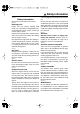
General information EMU25382 Important labels EMU25395 Warning labels ZMU01696 EMU25213 C-Tick label Engines affixed with this label conform to certain portion(s) of the Australian Radio Communications Act. ZMU04735 1 ZMU05721 ZMU02898 EMU25401 Label 1. C-Tick label location EWM01260 WARNING ● ● ● Be sure shift control is in neutral before starting engine. (except 2HP) Do not touch or remove electrical parts when starting or during operation.
General information ● starting device. The engine will not start unless the shift control is in neutral position. EMU25465 Caution labels ZMU04736 EMU30480 Label ECM01450 CAUTION: Use premix fuel only.
Safety information EMU33620 Safety information Observe these precautions at all times. EMU33630 Rotating parts Hands, feet, hair, jewelry, clothing, PFD straps, etc. can become entangled with internal rotating parts of the engine, resulting in serious injury or death. Keep the top cowling in place whenever possible. Do not remove or replace the cowling with the engine running. Only operate the engine with the cowling removed according to the specific instructions in the manual.
Safety information EMU33740 Boating safety This section includes a few of the many important safety precautions that you should follow when boating. EMU33710 Alcohol and drugs Never operate after drinking alcohol or taking drugs. Intoxication is one of the most common factors contributing to boating fatalities. EMU33720 Personal flotation devices Have an approved personal flotation device (PFD) on board for every occupant. Yamaha recommends that you must wear a PFD whenever boating.
Safety information EMU33790 Weather Stay informed about the weather. Check weather forecasts before boating. Avoid boating in hazardous weather. EMU33880 Passenger training Make sure at least one other passenger is trained to operate the boat in the event of an emergency. EMU33890 Boating safety publications Be informed about boating safety. Additional publications and information can be obtained from many boating organizations.
Basic requirements EMU25540 Fueling instructions EWM00010 WARNING GASOLINE AND ITS VAPORS ARE HIGHLY FLAMMABLE AND EXPLOSIVE! ● Do not smoke when refueling, and keep away from sparks, flames, or other sources of ignition. ● Stop engine before refueling. ● Refuel in a well-ventilated area. Refuel portable fuel tanks off the boat. ● Take care not to spill gasoline. If gasoline spills, wipe it up immediately with dry rags. ● Do not overfill the fuel tank. ● Tighten the filler cap securely after refueling.
Basic requirements 19. EMU25721 EWM01570 WARNING ● ● Improper mounting of the outboard motor could result in hazardous conditions such as poor handling, loss of control, or fire hazards. Because the motor is very heavy, special equipment and training is required to mount it safely. EMU33580 Remote control requirements The remote control unit must be equipped with a start-in-gear protection device(s). This device prevents the engine from starting unless it is in neutral.
Basic requirements where a different propeller would be more appropriate. Your Yamaha dealer can help you select the right propeller for your boating needs. Select a propeller that will allow the engine to reach the middle or upper half of the operating range at full throttle with the maximum boatload. Generally, chose a larger pitch propeller for a smaller operating load and a smaller pitch propeller for a heavier load.
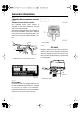
Basic components EMU2579B Main components NOTE: * May not be exactly as shown; also may not be included as standard equipment on all models. E25B, 25B, 25X, 30H 11 10 12 1 14 15 16 2 19 18 9 8 13 11 17 14 7 3 6 4 15 18 17 16 21 20 5 1. Top cowling 2. Top cowling lock lever 3. Anti-cavitation plate 4. Trim tab 5. Propeller 6. Cooling water inlet 7. Shallow water lever 8. Tilt rod 9. Clamp bracket 10. Clip 11. Manual starter handle 12. Engine stop button/Engine shut-off switch* 13.
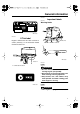
Basic components fuel tank, its function is as follows. EMU26180 Remote control EWM00020 WARNING The fuel tank supplied with this engine is its dedicated fuel reservoir and must not be used as a fuel storage container. Commercial users should conform to relevant licensing or approval authority regulations. The remote control lever actuates both the shifter and the throttle. The electrical switches are mounted on the remote control box. 2 1 4 3 ZMU02284 1. Fuel joint 2. Fuel gauge 3. Fuel tank cap 4.
Basic components 2. Forward “ ” 3. Reverse “ ” 4. Shift 5. Fully closed 6. Throttle 7. Fully open EMU26201 Neutral interlock trigger To shift out of neutral, first pull the neutral interlock trigger up. 1. Fully open 2. Fully closed EMU26221 Choke switch 1. Neutral interlock trigger To activate the choke system, press in the main switch while the key is turned to the “ ” (on) or “ ” (start) position. The choke system will then supply the rich fuel mixture required to start the engine.
Basic components ZMU02945 ZMU02937 EMU25961 EMU25922 Gear shift lever Throttle indicator Pulling the gear shift lever towards you puts the engine in forward gear so that the boat moves ahead. Pushing the lever away from you puts the engine in reverse gear so that the boat moves astern. The fuel consumption curve on the throttle indicator shows the relative amount of fuel consumed for each throttle position.
Basic components there is too much resistance, it could be difficult to move the remote control lever or throttle grip, which could result in an accident. ● ● ZMU02940 cure place on your clothing, or your arm or leg while operating. Do not attach the cord to clothing that could tear loose. Do not route the cord where it could become entangled, preventing it from functioning. Avoid accidentally pulling the cord during normal operation. Loss of engine power means the loss of most steering control.
Basic components 2. Cord EMU26001 Engine stop button To open the ignition circuit and stop the engine, push this button. ZMU02942 EMU26090 Main switch ZMU02905 EMU26011 Choke knob for pull type To supply the engine with the rich fuel mixture required to start, pull out this knob. The main switch controls the ignition system; its operation is described below. ” (off) ● “ With the main switch in the “ ” (off) position, the electrical circuits are off, and the key can be removed.
Basic components set according to operator preference. An adjusting screw or bolt is located on the swivel bracket. If the boat tends to veer to the right (starboard side), turn the trim tab end to the starboard side “B” in the figure. 1 A B 2 ZMU02908 To increase resistance, turn the adjuster clockwise. To decrease resistance, turn the adjuster counterclockwise. EWM00040 WARNING Do not overtighten the friction adjuster.
Basic components ZMU02947 ZMU02917 EMU30530 ECM00660 Tilt lock mechanism CAUTION: The tilt lock mechanism is used to prevent the outboard motor from lifting out of the water when in reverse gear. Do not use the tilt support lever or knob when trailering the boat. The outboard motor could shake loose from the tilt support and fall. If the motor cannot be trailered in the normal running position, use an additional support device to secure it in the tilt position.
Basic components EMU26410 2-pin connector AC 12 V-40/60/80W power is delivered through this connector. When using it, keep in mind the following points: the warning device will activate. Activation of warning device ● The engine speed will automatically decrease to about 2000 r/min. ● If equipped with an overheat-warning indicator, it will light or blink. ● The buzzer will sound (if equipped on the tiller handle, remote control box, or main switch panel).
Operation EMU26902 Installation The information presented in this section is intended as reference only. It is not possible to provide complete instructions for every possible boat and motor combination. Proper mounting depends in part on experience and the specific boat and motor combination. EWM01590 1 WARNING ● ● Overpowering a boat could cause severe instability. Do not install an outboard motor with more horsepower than the maximum rating on the capacity plate of the boat.
Operation ● ufacturer for further information on determining the proper mounting height. For instructions on setting the trim angle of the outboard motor, see page 33. EMU26970 Clamping the outboard motor 1. 0–25mm (0–1in.) ZMU02011 ECM01630 CAUTION: ● ● During water testing, check the buoyancy of the boat, at rest, with its maximum load.
Operation if it accidentally falls off the transom. wear in evenly. Correct break-in will help ensure proper performance and longer engine life. ECM00800 CAUTION: Failure to follow the break-in procedure could result in reduced engine life or even severe engine damage. EMU27050 ZMU02013 3. Gasoline and engine oil mixing chart (25:1) Secure the clamp bracket to the transom using the bolts provided with the outboard (if packed). For details, consult your Yamaha dealer.
Operation 3. 4. 5. Next two hours: Accelerate at full throttle onto plane, then reduce engine speed to three-quarter throttle (approximately 4000 r/min). Vary engine speed occasionally. Run at full throttle for one minute, then allow about 10 minutes of operation at threequarter throttle or less to let the engine cool. Remaining seven hours: Run the engine at any speed. However, avoid operating at full throttle for more than 5 minutes at a time. After the first 10 hours: Operate the engine normally.
Operation 2. sources of ignition. 1. 2. 3. Remove the fuel tank cap. Fill the fuel tank carefully. Close the cap securely after refueling. Wipe up any spilled fuel. Fuel tank capacity (if equipped Yamaha fuel tank): 24 L (6.34 US gal) (5.28 Imp.gal) EMU27405 Gasoline and oil mixing (100:1) Gasoline to engine oil ratio Break-in period After break-in See page 21 100:1 If equipped with a portable fuel tank 1. Pour oil into the portable fuel tank, and then add gasoline.
Operation line to the joint on the fuel tank. EMU27450 Operating engine EMU27463 Feeding fuel (portable tank) EWM00420 WARNING ● ● ● 1. Before starting the engine, make sure that the boat is tightly moored and that you can steer clear of any obstructions. Be sure there are no swimmers in the water near you. When the air vent screw is loosened, gasoline vapor will be released. Gasoline is highly flammable, and its vapors are flammable and explosive.
Operation or leg. Then install the clip on the other end of the cord into the engine shut-off switch. EWM00121 WARNING ● ● 1. Arrow ● EMU27491 Starting engine EWM01600 WARNING Before starting the engine, make sure that the boat is tightly moored and that you can steer clear of any obstructions. Be sure there are no swimmers in the water near you. Attach the engine shut-off cord to a secure place on your clothing, or your arm or leg while operating.
Operation ZMU02956 ZMU02954 4. Pull out / turn the choke knob fully. After the engine starts, replace / return the knob to the home position. 6. 7. After the engine starts, slowly return the manual starter handle to its original position before releasing it. Slowly return the throttle grip to the fully closed position. ZMU02955 NOTE: ● ● 5. It is not necessary to use the choke when starting a warm engine.
Operation N ZMU03087 NOTE: ZMU03088 3. The start-in-gear protection device prevents the engine from starting except when in neutral. 2. Attach the engine shut-off cord to a secure place on your clothing, or your arm or leg. Then install the clip on the other end of the cord into the engine shut-off switch. Open the throttle slightly without shifting using the neutral throttle lever. You may need to change the throttle opening slightly depending on engine temperature.
Operation small amount and try again. Also if the engine is warm and fails to start, open the throttle a small amount and try to start the engine again. If the engine still fails to start, see page 57. EMU27643 Electric start / remote control models 1. Place the remote control lever in neutral. ZMU02955 NOTE: ● ● 5. It is not necessary to use the choke when starting a warm engine. If the choke knob is left in the “ ” (start) position while the engine is running, the engine will run poorly or stall.
Operation the boat could slow rapidly. This could cause people and objects in the boat to be thrown forward. N ZMU02314 NOTE: ● 3. Turn the main switch to “ ” (on). ON ● OFF 5. ZMU01880 4. On remote controls equipped with a neutral throttle lever, a good starting point is to lift the lever just until you feel resistance, then lift slightly more. The neutral throttle lever or free accelerator can only be used when the remote control lever is in neutral.
Operation 6. Turn the main switch to “ ” (start), and hold it for a maximum of 5 seconds. cooling water pilot hole. ECM00511 CAUTION: OFF ON START ZMU02316 7. Immediately after the engine starts, release the main switch and allow it to return to “ ” (on). A continuous flow of water from the cooling water pilot hole shows that the water pump is pumping water through the cooling passages.
Operation engine and allow it to warm up. To shift out of neutral 1. Pull the neutral interlock trigger up (if equipped). N R F 1. Neutral interlock trigger 2. Move the remote control lever / gear shift lever firmly and crisply forward (for forward gear) or backward (for reverse gear) [about 35° (a detent can felt) for remote control models]. Be sure to check that the tilt lock lever is in the lock/down position (if equipped) before operating in reverse.
Operation ● ZMU02030 2. After the engine is at idle speed in gear move the remote control lever / gear shift lever firmly and crisply into the neutral position. pact the steering wheel or other parts of the boat. This could increase the risk of serious injury. It could also damage the shift mechanism. Do not shift into reverse while traveling at planing speeds. Loss of control, boat swamping, or damage to the boat could occur. The boat is not equipped with a separate braking system.
Operation ON OFF START gine shut-off switch, then turning the main switch to “ ” (off). EMU27861 Trimming outboard motor ZMU02973 2. After stopping the engine, disconnect the fuel line if there is a fuel joint on the outboard motor. The trim angle of the outboard motor helps determine the position of the bow of the boat in the water. Correct trim angle will help improve performance and fuel economy while reducing strain on the engine.
Operation 1 ZMU02976 1. Trim rod 1 ZMU02975 1. Trim operating angle 3. Reposition the rod in the desired hole. To raise the bow (“trim-out”), move the rod away from the transom. To lower the bow (“trim-in”), move the rod toward the transom. Make test runs with the trim set to different angles to find the position that works best for your boat and operating conditions.
Operation the boat is up about 3 to 5 degrees. With the bow up, the boat may have a greater tendency to steer to one side or the other. Compensate for this as you steer. The trim tab can also be adjusted to help offset this effect. When the bow of the boat is down, it is easier to accelerate from a standing start onto plane. and making it hard to increase speed. Operating with excessive trim-in at higher speeds also makes the boat unstable.
Operation the engine will be tilted for more than a few minutes. Otherwise fuel may leak. ECM00241 CAUTION: ● ● Before tilting the outboard motor, stop the engine by following the procedure on page 32. Never tilt the outboard motor while the engine is running. Severe damage from overheating can result. Do not tilt up the engine by pushing the tiller handle (if equipped) because this could break the handle. ZMU02979 3. Pull up the shallow water lever (if equipped).
Operation when trailering the boat. The outboard motor could shake loose from the tilt support and fall. If the motor cannot be trailered in the normal running position, use an additional support device to secure it in the tilt position. For more detailed information, see page 40. ● ● EMU28013 Procedure for tilting down (manual tilt models) 1. 2. Slightly tilt the engine up. On models equipped with a tilt support knob, pull it out.
Operation N ZMU02983 ZMU02917 4. N To return the outboard motor to the normal position, place the gear shift lever in neutral, then slightly tilt the outboard motor up. Push the shallow water lever down. Set the tilt lock lever to the lock position and slowly tilt the outboard motor down. EMU28193 ZMU03087 2. Push the tilt lock lever down to the release position. ZMU02984 3. Slightly tilt the outboard motor up and pull the shallow water lever toward the transom.
Maintenance EMU31480 Specifications NOTE: “(AL)” stated in the specification data below represents the numerical value for the aluminum propeller installed. Likewise, “(SUS)” represents the value for stainless steel propeller installed and “(PL)” for plastic propeller installed. EMU28219 Dimension: Overall length: 25BMH 843 mm (33.2 in) 25XMH 843 mm (33.2 in) 30HMH 843 mm (33.2 in) 30HW 608 mm (23.9 in) E25BMH 843 mm (33.2 in) Overall width: 25BMH 399 mm (15.7 in) 25XMH 399 mm (15.7 in) 30HMH 399 mm (15.
Maintenance 30HMH BR8HS-10 30HW BR8HS-10 E25BMH BR7HS-10 Spark plug gap: 0.9–1.0 mm (0.035–0.039 in) Control system: 25BMH Tiller 25XMH Tiller 30HMH Tiller 30HW Remote control E25BMH Tiller Starting system: 25BMH Manual 25XMH Manual 30HMH Manual 30HW Manual and electric E25BMH Manual Starting carburetion system: Choke valve Min. cold cranking amps (CCA/EN): 30HW 347.0 A Min. rated capacity (20HR/IEC): 30HW 40.
Maintenance ● ● transporting and storing the outboard motor, close the air vent screw and fuel cock to prevent fuel from leaking. USE CARE when transporting fuel tank, whether in a boat or car. DO NOT fill fuel container to maximum capacity. Gasoline will expand considerably as it warms up and can build up pressure in the fuel container. This can cause fuel leakage and a potential fire hazard. EWM00700 WARNING Never get under the lower unit while it is tilted, even if a motor support bar is used.
Maintenance lowing procedures. ECM01411 CAUTION: ● ● Do not place the outboard motor on its side before the cooling water has drained from it completely, otherwise water may enter the cylinder through the exhaust port and cause engine trouble. Store the outboard motor in a dry, wellventilated place, not in direct sunlight. EMU28303 1 2 ZMU02051 1. Water surface 2.
Maintenance 8. 9. 10. 11. 12. 13. cessively and almost stall. Remove the outboard motor from the test tank. Install the silencer cover/cap of fogging hole and top cowling. If the “Fogging Oil” is not available, run the engine at a fast idle until the fuel system becomes empty and the engine stops. Drain the cooling water completely out of the motor. Clean the body thoroughly. If the “Fogging Oil” is not available, remove the spark plug(s). Pour a teaspoonful of clean engine oil into each cylinder.
Maintenance Procedure 1. Disconnect and remove the battery from the boat. Always disconnect the black negative cable first to prevent the risk of shorting. 2. Clean the battery casing and terminals. Fill each cell to the upper level with distilled water. 3. Store the battery on a level surface in a cool, dry, well-ventilated place out of direct sunlight. 4. Once a month, check the specific gravity of the electrolyte and recharge as required to prolong battery life.
Maintenance EMU28522 Maintenance chart Frequency of maintenance operations may be adjusted according to the operating conditions, but the following table gives general guidelines. Refer to the sections in this chapter for explanations of each owner-specific action. NOTE: When operating in salt water, turbid or muddy water, the engine should be flushed with clean water after each use. The “ The “ ” symbol indicates the check-ups which you may carry out yourself.
Maintenance Initial Item Spark plug(s) Actions 10 hours (1 month) Every 50 hours (3 months) 100 hours (6 months) 200 hours (1 year) Cleaning / adjustment / replacement EMU28874 Maintenance chart (additional) Every Item Actions 500 hours (2.
Maintenance EMU28941 Greasing Yamaha grease A (water resistant grease) Yamaha grease D (corrosion resistant grease; for propeller shaft) E25B, 25B, 25X, 30H ZMU02918 EMU28953 Cleaning and adjusting spark plug EWM00560 WARNING When removing or installing a spark plug, be careful not to damage the insulator.
Maintenance fire. EWM01550 WARNING The engine will still be very hot when it has just been turned off. Take extremely care so that neither you nor anyone else gets burnt. To avoid burns, work on the engine when it has cooled down. The spark plug is an important engine component and is easy to inspect. The condition of the spark plug can indicate something about the condition of the engine.
Maintenance sources of ignition. EMU28980 Inspecting fuel filter EWM00910 EWM00310 WARNING WARNING Leaking fuel can result in fire or explosion. ● Check for fuel leakage regularly. ● If any fuel leakage is found, the fuel system must be repaired by a qualified mechanic. Improper repairs can make the outboard unsafe to operate. Check the fuel lines for leaks, crack, or malfunction. If a problem is found, your Yamaha dealer or other qualified mechanic should repair it immediately.
Maintenance solvent. Allow it to dry. Inspect the filter element and O-ring to make sure they are in good condition. Replace them if necessary. If any water is found in the fuel, the Yamaha portable fuel tank or other fuel tanks should be checked and cleaned. 2 3 4 1 ZMU02079 1. Filter cup 2. Filter element 3. Filter housing 4. O-ring 4. 5. 6. Reinstall the filter element in the cup. Make sure the O-ring is in position in the cup. Firmly screw the cup onto the filter housing.
Maintenance turning. ZMU02087 EMU29120 ZMU01896 Exhaust leakage Start the engine and check that no exhaust leaks from the joints between the exhaust cover, cylinder head, and body cylinder. EMU29130 Water leakage Start the engine and check that no water leaks from the joints between the exhaust cover, cylinder head, and body cylinder. EMU32110 Checking propeller ZMU01897 EWM01610 WARNING You could be seriously injured if the engine accidentally starts when you are near the propeller.
Maintenance age. 1. EMU30661 Removing propeller EMU29195 Spline models 1. Straighten the cotter pin and pull it out using a pair of pliers. 2. Remove the propeller nut, washer, and spacer (if equipped). 4 6 3. 4. 1 3 2. Apply Yamaha marine grease or a corrosion resistant grease to the propeller shaft. Install the spacer (if equipped), thrust washer, and propeller on the propeller shaft. Install the spacer (if equipped) and the washer. Tighten the propeller nut to the specified torque.
Maintenance 1. Tilt the outboard motor so that the gear oil drain screw is at the lowest point possible. Place a suitable container under the gear case. Remove the gear oil drain screw and gasket. 2. 3. sition, and using a flexible or pressurized filling device, inject the gear oil into the gear oil drain screw hole. Recommended gear oil: Hypoid gear oil SAE#90 Gear oil quantity: 320.0 cm3 (10.82 US oz) (11.29 Imp.oz) 2 1 ZMU02995 1. Gear oil drain screw 2.
Maintenance ● ● ● 1. 2. 3. an area with good ventilation. Wipe up any spilled fuel immediately. Reassemble the fuel tank carefully. Improper assembly can result in a fuel leak, which could result in a fire or explosion hazard. Dispose of old gasoline according to local regulations. Empty the fuel tank into an approved container. Pour a small amount of suitable solvent into the tank. Install the cap and shake the tank. Drain the solvent completely. Remove the screws holding the fuel joint assembly.
Maintenance and get immediate medical attention. Antidote (INTERNAL): ● Drink large quantities of water or milk followed by milk of magnesia, beaten egg, or vegetable oil. Get immediate medical attention. Batteries also generate explosive hydrogen gas; therefore, you should always follow these preventive measures: ● Charge batteries in a well-ventilated area. ● Keep batteries away from fire, sparks, or open flames (for example: welding equipment, lighted cigarettes, and so on.
Maintenance ● when installing the battery and disconnect the black battery cable first when removing it. The electrical contacts of the battery and cables must be clean and properly connected, or the battery will not start the engine. Connect the red battery cable to the POSITIVE (+) terminal first. Then connect the black battery cable to the NEGATIVE (-) terminal. ZMU04677 EMU29400 Coating the boat bottom A clean hull improves boat performance.
Trouble Recovery EMU29425 Troubleshooting A problem in the fuel, compression, or ignition systems can cause poor starting, loss of power, or other problems. This section describes basic checks and possible remedies, and covers all Yamaha outboard motors. Therefore some items may not apply to your model. If your outboard motor requires repair, bring it to your Yamaha dealer. If the engine trouble-warning indicator is flashing, consult your Yamaha dealer. Starter will not operate. Q.
Trouble Recovery A. Check for pinched or kinked fuel line or other obstructions in fuel system. Q. Is fuel contaminated or stale? A. Fill tank with clean, fresh fuel. Q. Is fuel filter clogged? A. Clean or replace filter. Q. Have ignition parts failed? A. Have serviced by a Yamaha dealer. Q. Has warning system activated? A. Find and correct cause of warning. Q. Is spark plug gap incorrect? A. Inspect and adjust as specified. Q. Is ignition wiring damaged or poorly connected? A.
Trouble Recovery Q. Is load on boat improperly distributed? A. Distribute load to place boat on an even plane. on gear housing? A. Remove foreign matter and clean lower unit. Q. Is water pump or thermostat faulty? A. Have serviced by a Yamaha dealer. Q. Is fuel system obstructed? A. Check for pinched or kinked fuel line or other obstructions in fuel system. Q. Is there excess water in fuel filter cup? A. Drain filter cup. Q. Is fuel filter clogged? A. Clean or replace filter. Engine power loss. Q.
Trouble Recovery Q. Is fuel joint connection incorrect? A. Connect correctly. Q. Is heat range of spark plug incorrect? A. Inspect spark plug and replace it with recommended type. trailering. Damage could make the outboard motor unsafe to operate. If the outboard motor hits an object in the water, follow the procedure below. Q. Is high pressure fuel pump drive belt broken? A. Have serviced by a Yamaha dealer. Q. Is engine not responding properly to shift lever position? A.
Trouble Recovery ● 3 2 1 ZMU02998 1. Fuse holder 2. Fuse (20 A) 3. Spare fuse (20 A) ● ● NOTE: Consult your Yamaha dealer if the new fuse immediately blows again. EMU29533 Starter will not operate If the starter mechanism does not operate (the engine cannot be cranked with the starter), the engine can be started with an emergency starter rope. ● EWM01022 WARNING ● ● ● ● Use this procedure only in an emergency to return to the nearest port for repairs.
Trouble Recovery 1 6. 7. ZMU02999 1. Start-in-gear protection cable 3. when the engine is cold. After the engine starts, gradually return the choke knob to its home position as the engine warms up. Insert the knotted end of the emergency starter rope into the notch in the flywheel rotor and wind the rope several turns around the flywheel clockwise. Give a strong pull straight out to crank and start the engine. Repeat if necessary. Remove the starter/flywheel cover after removing the bolt(s).
Trouble Recovery dealer as soon as possible. ECM00400 CAUTION: Do not attempt to run the outboard motor until it has been completely inspected. ZMU01909 2. Remove the spark plugs and face the spark plug holes downward to allow any water, mud, or contaminants to drain. ZMU01910 3. 4. Drain the fuel from the carburetor, fuel filter, and fuel line. Feed fogging oil or engine oil through the carburetor(s) and spark plug holes while cranking with the manual starter or emergency starter rope. ZMU01911 5.
YAMAHA MOTOR CO., LTD. Printed in Japan April 2007–0.