7NJ-9-12 Hyoshi 10/27/03 9:03 AM Page 1 Generator OWNER’S MANUAL EF1600 EF2600 YG2600 PRINTED ON RECYCLED PAPER PRINTED IN JAPAN 03 9 08 – 0.
7NJ-9-12 Hyoshi 10/27/03 9:03 AM Page 2
7NJ-9-12A 10/27/03 10:20 AM Page a AE00002 INTRODUCTION Congratulations on your purchase of your new Yamaha. This manual will provide you with a good basic understanding of the operation and maintenance of this machine. If you have any questions regarding the operation or maintenance of your machine, please consult a Yamaha dealer. PRI-I.D. NUMBER AE00012 IDENTIFICATION NUMBER RECORDS Record your Primary I.D.
7NJ-9-12A 10/27/03 10:20 AM Page b AE00032 w PLEASE READ AND UNDERSTAND THIS MANUAL COMPLETELY BEFORE OPERATING THE MACHINE. 851-005 NOTE: 9 Yamaha continually seeks advancements in product design and quality. Therefore, while this manual contains the most current product information available at the time of printing, there may be minor discrepancies between your engine and this manual. If there is any question concerning this manual, please consult your Yamaha dealer.
7NJ-9-12A 10/27/03 10:20 AM Page c AE00041 CONTENTS LIMITED WARRANTY (EF- AND PERIODIC MAINTENANCE ................18 EDL-SERIES) ........................................1 MAINTENANCE CHART ..................18 LIMITED WARRANTY (EC- AND SPARK PLUG INSPECTION............20 YG-SERIES) ..........................................2 CARBURETOR ADJUSTMENT .......20 LOCATION OF IMPORTANT ENGINE OIL REPLACEMENT .........21 LABELS.................................................4 AIR FILTER ..............
7NJ-9-12A 10/27/03 10:20 AM Page 1 AE01119 YAMAHA MOTOR CORPORATION U.S.A. EF- AND EDL-SERIES GENERATOR LIMITED WARRANTY Yamaha Motor Corporation, U.S.A. hereby warrants that new Yamaha consumer generators purchased from an authorized Yamaha consumer generator dealer in the continental United States will be free from defects in material and workmanship for the period of time stated herein, subject to certain stated limitations.
NJ-9-12A 10/27/03 10:20 AM Page 2 YAMAHA MOTOR CORPORATION U.S.A. EC- AND YG-SERIES INDUSTRIAL GENERATOR LIMITED WARRANTY Yamaha Motor Corporation, U.S.A. hereby warrants that new Yamaha EC- and YG-series generators purchased from an authorized Yamaha industrial generator dealer in the continental United States will be free from defects in material and workmanship for the period of time stated herein, subject to certain stated limitations.
7NJ-9-12A 10/27/03 10:20 AM Page 3 WARRANTY QUESTIONS AND ANSWERS Q. What costs are my responsibility during the warranty period? A. The customer’s responsibility includes all costs of normal maintenance service, nonwarranty repairs, accident damages, as well as oil and spark plugs. Q. What are some examples of “abnormal” strain, neglect, or abuse? A. These terms are general and overlap each other in areas.
7NJ-9-12A 10/27/03 10:20 AM Page 4 r w AE00062 LOCATION OF IMPORTANT LABELS Please read the following labels carefully before operating this machine. NOTE: Maintain or replace safety and instruction labels, as necessary. 792-003 te q 1 2 HOT EXHAUST WARNING Electrocution Or property damage can occur: Do not connect this generator to any building ’s electrical system unless an isolation switch has been installed by a licensed electrician. Refer to the owner’s manual.
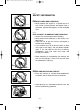
7NJ-9-12A 10/27/03 10:20 AM Page 5 AE00071 SAFETY INFORMATION AE00072 741-002 EXHAUST FUMES ARE POISONOUS 9 Never operate the engine in a closed area or it may cause unconsciousness and death within a short time. Operate the engine in a well ventilated area. AE00075 741-003 741-005 FUEL IS HIGHLY FLAMMABLE AND POISONOUS 9 Always turn off the engine when refuelling. 9 Never refuel while smoking or in the vicinity of an open flame.
7NJ-9-12A 10/27/03 10:20 AM Page 6 9 Keep the machine at least 1 m (3 ft) from buildings or other equipment, or the engine may overheat. a a 1 m (3 ft) 741-008a 9 Avoid operating the engine with a dust cover. 741-009 9 Be sure to carry the generator only by its carrying handle(s). q 1 Carrying handle(s) (shaded) 741-067 AE00083 ELECTRIC SHOCK PREVENTION 9 Never operate the engine in rain or snow. 741-010 9 Never touch the machine with wet hands or electrical shock will occur.
7NJ-9-12A 10/27/03 10:20 AM Page 7 Ground (earth) Lead Diameter: 0.12 mm (0.005 in)/ampere EX; 10 Ampere → 1.2mm (0.05 in) AE00088 CONNECTION NOTES 9 Avoid connecting the generator to commercial power outlet. 9 Avoid connecting the generator in parallel with any other generator.
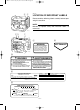
7NJ-9-12A 10/27/03 10:20 AM Page 8 EF1600/EF2600 !3 q AE00101 w !2 CONTROL FUNCTION !3 AE00102 DESCRIPTION i !0 o 793-015 YG2600 !3 q w !2 !3 1 2 3 4 5 6 7 8 9 0 q w e Fuel tank Fuel tank cap Fuel cock Air filter cover Spark plug Muffler Choke lever Ground (Earth) terminal Oil filler cap Oil drain plug Recoil starter Fuel level gauge Carrying handles (shaded) i !0 o !3 793-016 t !3 u e !1 r y 793-017 –8–
7NJ-9-12A 10/27/03 10:20 AM Page 9 EF1600 AE00104 w CONTROL BOX t 1 2 3 4 Engine switch Oil warning light Pilot light (YG2600) Voltage meter (EF1600/EF2600) 5 AC switch (N.F.B.) 6 AC receptacle 7 G.F.C.I.
7NJ-9-12A 10/27/03 10:20 AM Page 10 AE00111 OIL WARNING SYSTEM When the oil level falls below the lower level, the engine stops automatically. Unless you refill with oil, the engine will not start again. NOTE: If the engine stalls or does not start, turn the engine switch to "ON" position and then pull the recoil starter. If the oil warning light flickers for a few seconds, the engine oil is insufficient. Add oil and restart.
7NJ-9-12A 10/27/03 10:20 AM Page 11 AE00848 1 w 763-083 3 763-060 G.F.C.I. RECEPTACLE (for YG2600) The G.F.C.I. (Ground Fault Circuit Interrupter) 1 shuts off power to the protected receptacles if a ground fault (electrical leak) is detected. If the reset button 2 pops out 3, the equipment plugged into the receptacle may be faulty. If this happens, check the equipment carefully. If the equipment appears to be in good condition, press the reset button firmly until a click is heard.
7NJ-9-12A 10/27/03 10:20 AM Page 12 AE00845 PRE-OPERATION CHECK NOTE: Pre-operation checks should be made each time the generator is used. w The engine and muffler will be very hot after the engine has been run. Avoid touching the engine and muffler while they are still hot with any part of your body or clothing during inspection or repair. 741-001 AE00856 FUEL Make sure there is sufficient fuel in the tank.
7NJ-9-12A 10/27/03 10:20 AM Page 13 AE00222 ENGINE OIL Make sure the engine oil is at the upper level of the oil filler hole. Add oil as necessary. 1 Upper level 700-068 q 700-110 0°C 25°C A YAMALUBE 4(10W-30) D SAE 10W 32°F Recommended oil: å YAMALUBE 4 (10W-30) or SAE 10W-30 type SE motor oil ∫ SAE #30 ç SAE #20 ∂ SAE 10W Engine oil quantity: 0.6 L (0.53 lmp qt, 0.63 US qt) C SAE #20 B SAE #30 80°F NOTE: Recommended engine oil classification: API Service “SE” or “SF”.
7NJ-9-12A 10/27/03 10:21 AM Page 14 AE00955 OPERATION q 700-006a NOTE: The generator has been shipped without engine oil. Fill with oil or it will not start. 1 Upper level AE00854 STARTING THE ENGINE 761-027 ON NOTE: 9 Before starting the engine, do not connect any electric devices. 9 Turn the AC switch (N.F.B.) to the “OFF” position. 1 3 “OFF” OFF q 763-086e 1. Turn the fuel cock lever to the “ON” position. 1 “ON” q 705-037 2. Turn the engine switch to the “ON” position.
7NJ-9-12A 10/27/03 10:21 AM Page 15 4. Pull slowly on the recoil starter until it is engaged, then pull it briskly. 5. After the engine starts, warm up the engine until the engine does not stop when the choke lever is returned to the operating position. 704-010 6. Turn the choke lever back to the operating position. q 1 Operating position 701-025 AE00343 APPLICATION RANGE AC 779-006a 779-006c 779-006b Power factor 1 0.8–0.95 0.4–0.75 (Efficiency 0.
7NJ-9-12A 10/27/03 10:21 AM Page 16 AE00851 CONNECTION Alternating Current (AC) cC 9 Be sure all electric devices including the lines and plug connections are in good condition before connection to the generator. 9 Be sure any electric devices are turned off before plugging it in. 9 Be sure the total load is within generator rated output. 9 Be sure the receptacle load current is within receptacle rated current. A B 1. Wind the power lead 2 or 3 turns around frame. å EF1600/EF2600 ∫ YG2600 761-029 2.
7NJ-9-12A 10/27/03 10:21 AM Page 17 AE00852 STOPPING THE ENGINE NOTE: 9 Turn off any electric devices. 9 Turn the AC switch (N.F.B.) to the “OFF” position. 1 3 “OFF” 1. Disconnect any electric devices. q 763-094a 2. Turn the engine switch to the “STOP” position. 1 5 “STOP” q 763-085e 3. Turn the fuel cock lever to “OFF”.
7NJ-9-12B 10/27/03 9:59 AM Page 18 AE00401 PERIODIC MAINTENANCE AE00403 MAINTENANCE CHART Regular maintenance is most important for best performance and safe operation. w Stop the engine before starting maintenance work. No. Item Remarks Every Pre-Ope- Initial ration 1 3 6 12 check month months months months (daily) or 20 Hr or 50 Hr or 100 Hr or 300 Hr ** Spark Plug Check condition. Adjust gap and clean. Replace if necessary. 2.* ** Valve Clearance Check and adjust when engine is cold.
7NJ-9-12B 10/27/03 9:59 AM Page 19 No. Item Remarks Every Pre-Ope- Initial ration 1 3 6 12 check month months months months (daily) or 20 Hr or 50 Hr or 100 Hr or 300 Hr Fuel Filter Clean fuel cock and fuel tank filter. Replace if necessary. Fuel Line Check fuel hose for crack or damage. *Replace if necessary. 0 10. ** Choke lever Check choke operation. 0 11. Cooling System Check for fan damage. 12. Starting System Check recoil starter operation. ** 13.
7NJ-9-12B 10/27/03 9:59 AM Page 20 AE00423 SPARK PLUG INSPECTION You should periodically remove and inspect the spark plug. 1. Check for discoloration and remove the carbon. 760-005a Standard electrode color: Tan Color 2. Check the spark plug type and gap. a 760-001a Standard Spark Plug: BPR4ES (NGK) Spark Plug Gap: 0.7–0.8 mm (0.028–0.031 in) a Gap 3. Install the spark plug. Spark Plug Torque: 20 N•m (2 kgf•m, 14 lbf•ft) AE00431 CARBURETOR ADJUSTMENT The carburetor is a vital part of the engine.
7NJ-9-12B 10/27/03 9:59 AM Page 21 AE00412 ENGINE OIL REPLACEMENT 1. Place the machine on a level surface and warm up the engine for several minutes. Then stop the engine. 2. Remove the oil filler cap. 3. Place an oil pan under the engine. Remove the oil drain plug so that the oil can be completely drained. 4. Check the drain plug, gasket, oil filler cap and Oring. If damaged, replace. e w q 700-067 1 Oil drain plug 2 Gasket 3 O-ring 5. Reinstall the oil drain plug. Drain Plug Torque: 17 N•m (1.
7NJ-9-12B 10/27/03 9:59 AM Page 22 AE00451 AIR FILTER 1. Remove the air filter cover and element. 2. Wash the element in solvent and dry. 3. Oil the element and squeeze out excess oil. The element should be wet but not dripping. Recommended oil: Foam-air-filter oil or SAE #20 motor oil cC Do not wring out the element. This could cause it to tear. 4. Insert the element into the air filter. 710-037a NOTE: Be sure the element sealing surface matches the air filter so there is no air leak.
7NJ-9-12B 10/27/03 9:59 AM Page 23 AE00855 FUEL COCK B A w Never use or be near fuel and solvent while smoking or in the vicinity of an open flame. A 1. 2. 3. 4. 5. 6. B Stop the engine. Turn the fuel cock lever to “OFF”. Remove the fuel cock cup and gasket. Clean the cup with solvent and wipe it off. Check the gasket. Replace it if damaged. Reinstall the gasket and fuel cock cup. w Be sure the fuel cock cup is tightened securely.
7NJ-9-12B 10/27/03 9:59 AM Page 24 AE00853 MUFFLER SCREEN AND SPARK ARRESTER w 741-001 The engine and muffler will be very hot after the engine has been run. Avoid touching the engine and muffler while they are still hot with any part of your body or clothing during inspection or repair. 1. Remove the muffler screen. q 1 Muffler screen 2 Screw w 711-015 2. Use a flathead screw driver to pry the spark arrester out from the muffler. 711-012b 3. Remove the spark arrester.
7NJ-9-12B 10/27/03 9:59 AM Page 25 6. Install the spark arrester. q NOTE: Align the spark arrester projection with the hole in the muffler pipe. 711-012a 1 Projection 2 Hole 7. Install the muffler screen. 711-017a AE00501 w q 763-083a 3 4 763-059 G.F.C.I. RECEPTACLE TEST (YG2600) 1. Start the engine. 2. Turn the AC switch (N.F.B.) to the “ON” position. 3. Press the test button 1, then check the position of the reset button 2. G.F.C.I. Reset Button Position after Test G.F.C.I.
7NJ-9-12B 10/27/03 9:59 AM Page 26 AE00512 TROUBLESHOOTING 707-001 Engine won’t start 1. Fuel systems No fuel supplied to combustion chamber. 2 No fuel in tank .... Supply fuel. 2 Clogged fuel line .... Clean fuel line. 2 Foreign matter in fuel cock .... Clean fuel cock. 2 Clogged carburetor .... Clean carburetor. 705-037a 2. Engine oil system Insufficient 2 Oil level is low .... Add engine oil. 700-006 763-084i 3. Electrical systems 2 Engine switch to “ON”.
7NJ-9-12B 10/27/03 9:59 AM Page 27 AE00515 A ENGINE DOES NOT START B Turn the engine switch to “ON”, then pull the recoil starter and check if the oil warning light flickers. E Check engine oil level. 791-001c 791-001e C H Does not flicker D F Flickers OK Consult a Yamaha dealer. G Level low Add engine oil. Pull the recoil starter and check the spark plug for spark strength. (See “WARNING”) K Check the spark plug.
7NJ-9-12B 10/27/03 9:59 AM Page 28 AE00601 q STORAGE Long term storage of your machine will require some preventive procedures to guard against deterioration. AE00611 a w DRAIN THE FUEL 1. Drain the fuel tank, fuel cock, and carburetor float bowl. a Carburetor drain plug e 2. Pour a cup of SAE 10W30 or 20W40 motor oil into the tank. 3. Shake the tank to coat the inner surfaces thoroughly. 4. Drain off the excess oil. r 707-038 AE00621 ENGINE 1.
7NJ-9-12B 10/27/03 9:59 AM Page 29 AE00789 EXHAUST EMISSION CONTROL SYSTEM AND COMPONENTS Item Acronym 9 CARB. ASSY., LH. & JT., .............................CARB (Carburetor) CARBURETOR2 9 T.C.I. MAGNETO ASSY. & ..........................EI (Electronic Ignition) PLUG, SPARK 9 CRANKCASE1 & HEAD, ..............................PCV (Positive Crankcase CYLINDER1 Ventilation) 9 AIR FILTER ASSY. .......................................ACL (Air Cleaner) 9 MUFF.
7NJ-9-12B 10/27/03 9:59 AM Page 30 AE00701 SPECIFICATIONS AE00702 DIMENSIONS Overall Length Overall Width Overall Height Dry Weight Unit mm (in) mm (in) mm (in) kg (lb) EF1600 510 (20.1) 415 (16.3) 425 (16.7) 38 (83.8) EF2600 510 (20.1) 415 (16.3) 425 (16.7) 41 (90.4) YG2600 593 (23.3) 487 (19.2) 534 (21.0) 46.5 (102.
7NJ-9-12B 10/27/03 9:59 AM Page 31 AE00751 WIRING DIAGRAM EF1600/EF2600 Generator assembly 1 Control box Br Br 4 2 Br Br V 3 3 Br w R R R R R G G G G G G G G G G G/Y G/Y 6 G/Y 8 G/Y 1(for EF1600) B/W 5 q B Y Frame earth B/W L Y B/W B B L B/W Engine (For EF1600) 9 7 0 Br 3 R G/Y Color code 1 Rotor assembly 2 Stator assembly 3 AC receptacle 4 AC switch (N.F.B.) 5 Engine switch 6 Condenser 7 Oil level switch 8 Oil warning unit 9 T.C.I.
7NJ-9-12B 10/27/03 9:59 AM Page 32 YG2600 Generator assembly q Control box Br Br r w Br Br e Br e !2 R R R R R G/Y G G G G G G G G G G G/Y G/Y y G/Y G/Y t i G/Y !1 B B/W Y G/Y L Y B/W B Frame earth B/W B L B/W Engine o u !0 770-008 Color code 1 Rotor assembly 2 Stator assembly 3 AC receptacle 4 AC switch (N.F.B.) 5 Engine switch 6 Condenser 7 Oil level switch 8 Oil warning unit 9 T.C.I.
7NJ-9-12B 10/27/03 9:59 AM Page 33 AE00795 ENGINE HANGER INSTALLATION (for YG2600) 794-001 – 33 –
7NJ-9-12 Hyoshi 10/27/03 9:03 AM Page 1 Generator OWNER’S MANUAL EF1600 EF2600 YG2600 PRINTED ON RECYCLED PAPER PRINTED IN JAPAN 03 9 08 – 0.