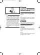
7CF-9-10 hyoshi 2/15/05 3:01 PM Page 1 Generator OWNER’S MANUAL EF2400iS PRINTED ON RECYCLED PAPER PRINTED IN JAPAN 05 9 02 – 0.
7CF-9-10 hyoshi 2/15/05 3:01 PM Page 2
7CF-9-10-a 3/9/05 9:21 AM Page 0-1 AE00002 INTRODUCTION Congratulations on your purchase of your new Yamaha. This manual will provide you with a good basic understanding of the operation and maintenance of this machine. If you have any questions regarding the operation or maintenance of your machine, please consult a Yamaha dealer. PRI-I.D. NUMBER AE00012 IDENTIFICATION NUMBER RECORDS Record your Primary I.D.
7CF-9-10-a 3/9/05 9:21 AM Page 0-2 AE00032 w PLEASE READ AND UNDERSTAND THIS MANUAL COMPLETELY BEFORE OPERATING THE MACHINE. NOTE: 9 Yamaha continually seeks advancements in product design and quality. Therefore, while this manual contains the most current product information available at the time of printing, there may be minor discrepancies between your engine and this manual. If there is any question concerning this manual, please consult your Yamaha dealer.
7CF-9-10-a 3/9/05 9:21 AM Page 0-3 AE00041 CONTENTS LIMITED WARRANTY (EF- AND EDL-SERIES)..........................................1 PERIODIC MAINTENANCE .................20 LOCATION OF IMPORTANT LABELS ..3 SPARK PLUG INSPECTION .............22 SAFETY INFORMATION ........................5 CARBURETOR ADJUSTMENT.........22 MAINTENANCE CHART ...................20 EXHAUST FUMES ARE ENGINE OIL REPLACEMENT ..........23 POISONOUS .......................................
7CF-9-10-a 3/9/05 9:21 AM Page 1 AE01120 YAMAHA MOTOR CORPORATION U.S.A. EF- AND EDL-SERIES GENERATOR LIMITED WARRANTY Yamaha Motor Corporation, U.S.A. hereby warrants that new Yamaha consumer generators purchased from an authorized Yamaha consumer generator dealer in the continental United States will be free from defects in material and workmanship for the period of time stated herein, subject to certain stated limitations.
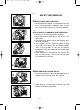
CF-9-10-a 3/9/05 9:21 AM Page 2 WARRANTY QUESTIONS AND ANSWERS Q. What costs are my responsibility during the warranty period? A. The customer’s responsibility includes all costs of normal maintenance service, non-warranty repairs, accident damages, as well as oil and spark plugs. Q. Is the warranty transferable to second owners? A. Yes. The remainder of the existing warranty can be transfered upon request.
7CF-9-10-a 3/9/05 9:21 AM Page 3 AE00062 LOCATION OF IMPORTANT LABELS Please read the following labels carefully before operating this machine. NOTE: Maintain or replace safety and instruction labels, as necessary.
7CF-9-10-a 3/9/05 9:21 AM Page 4 1 2 OIL HOT EXHAUST ***-28176-** zzzzzz AC output Rated zzHz zzzKVA zzzV Phase DC output Fuel Single zzV zzA Gasoline YAMAHA MOTOR CO., LTD. MADE IN JAPAN ***-24164-** 3 ENGINE AIR INDEX ( C a l i f o r n i a only ) IMPORTANT ENGINE INFORMATION ENGINE FAMILY : zzzzzzzzzzzz E M 0 REFER TO OWNER'S MANUAL FOR MAINTENANCE SPECIFICATIONS AND ADJUSTMENTS. DISPLACEMENT: zzz J IGNITION TIMING & IDLE MIXTURE IDLE SPEED: zzzz~zzzz VALVE LASH (A) IN: z.zz~z.
7CF-9-10-a 3/9/05 9:21 AM Page 5 AE00071 SAFETY INFORMATION AE00072 741-112 EXHAUST FUMES ARE POISONOUS 9 Never operate the engine in a closed area or it may cause unconsciousness and death within a short time. Operate the engine in a well ventilated area. AE00075 741-113 741-114 FUEL IS HIGHLY FLAMMABLE AND POISONOUS 9 Always turn off the engine when refuelling. 9 Never refuel while smoking or in the vicinity of an open flame.
7CF-9-10-a 3/9/05 9:21 AM Page 6 9 Keep the machine at least 1 m (3 ft) from buildings or other equipment, or the engine may overheat. a a 1 m (3 ft) 741-118 9 Avoid operating the engine with a dust cover. 741-119 9 Be sure to carry the generator only by its carrying handle(s). 1 1 Carrying handle(s) (shaded) 741-124 AE00083 ELECTRIC SHOCK PREVENTION 9 Never operate the engine in rain or snow. 741-120 9 Never touch the machine with wet hands or electrical shock will occur.
7CF-9-10-a 3/9/05 9:21 AM Page 7 Ground (earth) Lead Diameter: 0.12 mm (0.005 in)/ampere EX; 10 Ampere → 1.2 mm (0.05 in) AE01181 CONNECTION NOTES 9 Avoid connecting the generator to commercial power outlet. 1 1 Correct 2 Incorrect AE00091 2 CONNECTION w 1 741-122 Before the generator can be connected to a building’s electrical system, a licensed electrician must install an isolation (transfer) switch in the building’s main fuse box.
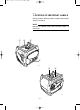
7CF-9-10-a 3/9/05 9:21 AM Page 8 AE00101 23 1 CONTROL FUNCTION 1 AE00102 DESCRIPTION 1 2 3 4 5 6 7 6 1 5 4 793-146 AE00103 32 1 CONTROL PANEL 1 2 3 4 5 6 7 8 9 7 Carrying handles (shaded) Fuel level gauge Fuel tank cap Oil filler cap Recoil starter Fuel cock Muffler Engine switch Twin Tech (parallel running terminal) DC protector Oil warning light AC pilot light Overload indicator light AC receptacle DC receptacle Ground (Earth) terminal 793-147 q o w e i –8– t r u y 793-148
7CF-9-10-a 3/9/05 9:21 AM Page 9 AE00111 OIL WARNING SYSTEM When the oil level falls below the lower level, the engine stops automatically. Unless you refill with oil, the engine will not start again. NOTE: If the engine stalls or does not start, turn the engine switch to “ON” position and then pull the recoil starter. If the oil warning light flickers for a few seconds, the engine oil is insufficient. Add oil and restart. AE00124 700-121 ENGINE SWITCH The engine switch controls the ignition system.
7CF-9-10-a 3/9/05 9:21 AM Page 10 AE00845 PRE-OPERATION CHECK NOTE: Pre-operation checks should be made each time the generator is used. w 741-123 The engine and muffler will be very hot after the engine has been run. Avoid touching the engine and muffler while they are still hot with any part of your body or clothing during inspection or repair. AE00856 FUEL Make sure there is sufficient fuel in the tank. q 707-033c Recommended fuel: Unleaded gasoline Fuel tank capacity: Total: 6.0 L (1.
7CF-9-10-a 3/9/05 9:21 AM Page 11 AE00222 ENGINE OIL Make sure the engine oil is at the upper level of the oil filler hole. Add oil as necessary. 700-128 1 Upper level q 700-103c 0°C 25°C Recommended oil: å YAMALUBE 4 (10W-30) or SAE 10W-30 type SE motor oil ∫ SAE #30 ç SAE #20 ∂ SAE 10W Engine oil quantity: 0.6 L (0.53 lmp qt, 0.63 US qt) A YAMALUBE 4(10W-30) D SAE 10W 32°F C SAE #20 B SAE #30 80°F NOTE: Recommended engine oil classification: API Service “SE” or “SF”.
7CF-9-10-a 3/9/05 9:21 AM Page 12 AE00955 OPERATION a 700-006a NOTE: The generator has been shipped without engine oil. Fill with oil or it will not start. 1 Upper level AE01171 STARTING THE ENGINE 761-085 NOTE: 9 Before starting the engine, do not connect any electric devices. 1. Turn the fuel cock lever to the “ON” position. 1 1 “ON” 705-075 2. Pull the choke knob fully out. 2 2 Choke knob 701-051 e NOTE: The choke is not required to start a warm engine.
7CF-9-10-a 3/9/05 9:21 AM Page 13 4. Pull slowly on the recoil starter until it is engaged, then pull it briskly. 5. After the engine starts, warm up the engine until the engine does not stop when the choke knob is returned to the original position. 704-019 6. Push the choke knob back to the original position.
7CF-9-10-a 3/9/05 9:21 AM Page 14 AE01180 APPLICATION RANGE AC DC Power factor 1 0.8–0.95 0.4–0.75 (Efficiency 0.85) EF2400iS –2,000W –1,600W –680W Rated voltage 12V Rated current 8A NOTE: 9 “–” means below. 9 Application wattage indicates when each device is used by itself. 9 The overload indicator light 1 comes on when total wattage exceeds the application range. (See page 16 for more details.
7CF-9-10-a 3/9/05 9:21 AM Page 15 AE01172 CONNECTION Alternating Current (AC) cC 761-086 9 Be sure all electric devices including the lines and plug connections are in good condition before connection to the generator. 9 Be sure any electric devices are turned off before plugging it in. 9 Be sure the total load is within generator rated output. 9 Be sure the receptacle load current is within receptacle rated current. 1. Wind the power lead 2 or 3 turns around handle. 2. Start the engine. 3.
7CF-9-10-a 3/9/05 9:21 AM Page 16 AE00788 q 760-029 Overload indicator light The overload indicator light 1 comes on when an overload of a connected electrical device is detected, the inverter control unit overheats, or the AC output voltage rises. The electronic breaker will then activate, stopping power generation in order to protect the generator and any connected electric devices.
7CF-9-10-a 3/9/05 9:21 AM Page 17 AE00904 Battery Charging cC Do not use AC and DC power at the same time or the generator may be damaged. NOTE: The generator DC rated voltage is 12V. 1. Wind the battery charging lead 2 or 3 turns around the handle and plug into DC receptacle. 761-086a 2 1 762-046 NOTE: 9 Make connections to the battery after starting the engine. 9 Clamp the red wire to the positive (+) terminal and the black wire to the negative (-) terminal of the battery.
7CF-9-10-a 3/9/05 9:21 AM Page 18 w Never smoke or make and break connections at the battery while charging. Sparks may ignite the battery gas. Battery electrolyte is poisonous and dangerous, causing severe burns, etc. contains sulfuric (sulphuric) acid. Avoid contact with skin, eyes or clothing. Antidote: EXTERNAL-Flush with water. INTERNAL-Drink large quantities of water or milk. Follow with milk of magnesia, beaten egg or vegetable oil. Call physician immediately.
7CF-9-10-a 3/9/05 9:21 AM Page 19 AE01173 STOPPING THE ENGINE NOTE: 9 Turn off any electric devices. 761-085 1. Disconnect any electric devices. 2. Turn the engine switch to the “5” (STOP) position. 1 5 “STOP” q 763-262 3. Turn the fuel cock lever to “OFF”.
7CF-9-10-b 3/9/05 10:35 AM Page 20 AE00401 PERIODIC MAINTENANCE AE00403 MAINTENANCE CHART Regular maintenance is most important for best performance and safe operation. w Stop the engine before starting maintenance work. No. Item Remarks Every Pre-Ope- Initial ration 1 3 6 12 check month months months months (daily) or 20 Hr or 50 Hr or 100 Hr or 300 Hr ** Spark Plug Check condition. Adjust gap and clean. Replace if necessary. 2.* ** Valve Clearance Check and adjust when engine is cold.
7CF-9-10-b 3/9/05 10:35 AM Page 21 No. Item Remarks Every Pre-Ope- Initial ration 1 3 6 12 check month months months months (daily) or 20 Hr or 50 Hr or 100 Hr or 300 Hr Fuel Filter Clean fuel tank filter. Replace if necessary. Fuel Line Check fuel hose for crack or damage. *Replace if necessary. 0 10. ** Choke knob Check choke operation. 0 11. Cooling System Check for fan damage. 12. Starting System Check recoil starter operation. ** 13.* Decarbonization More frequently if necessary. 14.
7CF-9-10-b 3/9/05 10:35 AM Page 22 AE01051 2 1 1 788-014 SPARK PLUG INSPECTION You should periodically remove and inspect the spark plug. 1. Loosen the bolt 1 and remove the side cover 2. 2. Remove the spark plug cap and the spark plug. 3. Check for discoloration and remove the carbon. Standard electrode color: Tan Color 4. Check the spark plug type and gap. 760-031 Standard Spark Plug: BPR4ES (NGK) Spark Plug Gap: 0.7–0.8 mm (0.028–0.031 in) a Gap a 5. Install the spark plug.
7CF-9-10-b 3/9/05 10:35 AM Page 23 AE01174 ENGINE OIL REPLACEMENT 1. Place the machine on a level surface and warm up the engine for several minutes. Then stop the engine. 2. Remove the rubber cap 1 on the bottom. 1 700-130 3. Place an oil pan under the engine . Remove the drain bolt 2. 5 2 700-132 4. Open the oil filler cover 3 as shown and remove the oil filler cap 4 so that the oil can be completely drained. 3 4 5. Check the drain bolt , gasket 5, oil filler cap and Oring 6.
7CF-9-10-b 3/9/05 10:35 AM Page 24 0°C 25°C A YAMALUBE 4(10W-30) D SAE 10W 32°F C SAE #20 B SAE #30 80°F 700-065 Recommended oil: å YAMALUBE 4 (10W-30) or SAE 10W-30 type SE motor oil ∫ SAE #30 ç SAE #20 ∂ SAE 10W Engine oil quantity: 0.6 L (0.53 Imp qt, 0.63 US qt) NOTE: Recommended engine oil classification: API Service “SE” or “SF”. cC Be sure no foreign material enters the crankcase. 8. Install the oil filler cap. 9. Install the rubber cap on the bottom.
7CF-9-10-b 3/9/05 10:35 AM Page 25 3. Use a flathead screw driver to pry the spark arrester out from the muffler. 711-078 4. Remove the spark arrester. q 1 Spark arrester 711-079 5. Remove the carbon deposits on the muffler screen and spark arrester using a wire brush. cC 711-075 When cleaning, use the wire brush lightly to avoid damaging or scratching of the muffler screen and spark arrester. 6. Check the muffler screen and spark arrester. Replace them if damaged. 7. Install the spark arrester.
7CF-9-10-b 3/9/05 10:35 AM Page 26 E01175 1 1 AIR FILTER 1. Loosen the bolt 1 and remove the cover 2. 2 788-017 2. Remove the air filter cover and element. 3. Wash the foam element in solvent and dry. 4. Oil the foam element and squeeze out excess oil. The foam element should be wet but not dripping. Recommended oil: Foam-air-filter oil or SAE #20 motor oil cC Do not wring out the element. This could cause it to tear. 5. Insert the element into the air filter.
7CF-9-10-b 3/9/05 10:35 AM Page 27 AE00471 FUEL TANK FILTER 1. Remove the fuel tank cap and filter. q 1 Filter 2. Clean the filter with solvent. If damaged, replace. 3. Wipe the filter and insert it. w Be sure the tank cap is tightened securely.
7CF-9-10-b 3/9/05 10:35 AM Page 28 AE01176 TROUBLESHOOTING 707-106 Engine won’t start 1. Fuel systems No fuel supplied to combustion chamber. 2 No fuel in tank .... Supply fuel. 2 Fuel in tank .... Fuel cock lever to “ON”. 2 Clogged fuel line .... Clean fuel line. 2 Clogged carburetor .... Clean carburetor. 705-075b 2. Engine oil system Insufficient 2 Oil level is low .... Add engine oil. 700-006 763-261a 3. Electrical systems 2 Engine switch to “ON”.
7CF-9-10-b 3/9/05 10:35 AM Page 29 AE00515 A ENGINE DOES NOT START B Turn the engine switch to “ON”, then pull the recoil starter and check if the oil warining light flickers. C H Does not flicker D E F Flickers. Check engine oil level. OK Consult a Yamaha dealer. G Level low Add engine oil. Pull the recoil starter and check the spark plug for spark strength. (See “WARNING”) K L w 9 To prevent FIRE HAZARDS be sure fuel is not present in the spark plug area.
7CF-9-10-b 3/9/05 10:35 AM Page 30 AE00601 STORAGE Long term storage of your machine will require some preventive procedures to guard against deterioration. AE01177 DRAIN THE FUEL 1. Remove the fuel tank cap. Drain the fuel from the fuel tank into an approved gasoline container using a commercially available hand siphon. Then, install the fuel tank cap. w 9 Fuel is highly flammable and poisonous. Check “SAFETY INFORMATION” (See page 5) carefully. 9 Wipe up any spilled fuel immediately. 1 707-109 2.
7CF-9-10-b 3/9/05 10:35 AM Page 31 AE00789 EXHAUST EMISSION CONTROL SYSTEM AND COMPONENTS Item Acronym 9 CARB. ASSY., LH. & JT., .......................CARB (Carburetor) CARBURETOR2 9 T.C.I. MAGNETO ASSY. & ....................EI (Electronic Ignition) PLUG, SPARK 9 CRANKCASE1 & HEAD, .......................PCV (Positive Crankcase CYLINDER1 Ventilation) 9 AIR FILTER ASSY. .................................ACL (Air Cleaner) 9 MUFF.
7CF-9-10-b 3/9/05 10:35 AM Page 32 AE00701 SPECIFICATIONS AE00702 DIMENSIONS Overall Length Overall Width Overall Height Dry Weight Unit mm (in) mm (in) mm (in) kg (lb) EF2400iS 527 (20.7) 419 (16.5) 461 (18.
7CF-9-10-b 3/9/05 10:35 AM Page 33 AE00751 WIRING DIAGRAM q W W W Y Y Y Y Y Y W W O L W W O L e O O O O L B @0 Br Br R R Br y u R O G Y Y R G/Y G L O L B/W B/W Y Y !0 Y W !1 B B/W B G/Y !2 B/W B/W B/W O O O o G/Y B/W !8 i R t BW G Y R L O G/Y R R L w Br Br R Br r O L L !9 !7 !6 !5 L B/W O Y G/Y O O G/Y G/Y !3 L B/W Y Y !4 770-054 1 Main coil 2 DC coil 3 Sub coil 4 DC rectifier 5 Control unit 6 AC pilot light 7 Parallel terminal 8 AC recepta
7CF-9-10 hyoshi 2/15/05 3:01 PM Page 1 Generator OWNER’S MANUAL EF2400iS PRINTED ON RECYCLED PAPER PRINTED IN JAPAN 05 9 02 – 0.
) AREA CODE PHONE NUMBER ( CITY & STATE ADDRESS ZIP MAIL THIS TO YAMAHA MOTOR CORPORATION, U.S.A. 9 Please complete and mail this form. It will help ensure that Yamaha has accurately registered your purchase for warranty. 9 Manufacturers are required to maintain a complete up-to-date list of all first purchasers of products against the possibility of a safety-related defect and recall.
Page 2 6/29/04 3:05 PM WarrantyCard_US PLACE STAMP HERE YAMAHA MOTOR CORPORATION U.S.A. P.O.