YAMAHA ® AUTHORIZED PRODUCT MANUAL DIGITAL PROGRAMMABLE ALGORITHM SYNTHESIZER
YAMAHA ® DIGITAL PROGRAMMABLE ALGORITHM SYNTHESIZER OWNER’S MANUAL
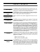
CONGRATULATIONS! Your Yamaha DX100 Digital Programmable Algorithm Synthesizer incorporates stateof-the-art digital FM tone generation technology, providing extraordinarily vibrant, rich voices and outstanding playability.
PRECAUTIONS 1. Location Avoid locations exposed to direct sunlight or other sources of heat. Also avoid locations subject to vibration, excessive dust, cold or moisture. 2. Cleaning Do not attempt to clean the exterior with chemical solvents, as this may damage the finish. Clean with a soft, dry cloth. 3. Service and Modifications Do not open the cabinet or attempt to make your own repairs or modifications to any part of the instrument.
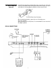
CHAPTER I: SETTING UP 1. Audio Outputs 2. Optional Foot Switch 3. Optional BC-1 Breath Con troller 4. Headphones 5. MIDI Terminals 6. Cassette The DX100 has a single mono audio output for its tone generator channel. This is labelled OUTPUT. It permits sending a mono signal to either a mono or stereo sound system, or a mixing console for recording or PA applications. The FOOT SW phone jack is for an optional footswitch.
NOTE: When setting up your system, be sure to turn the DX100 and any effects units used on BEFORE turning the main amplifier system on. This will prevent the initial power-on shock surge from possibly damaging your amplifier and speaker system. The DX100 features a Power-ON LED indicator, located immediately to the right of the LCD indicator on the top panel. It glows when the Power switch on the rear 8. Power-ON, Low Battery LED Indicator panel is turned ON.
11. When using dry batteries Insert 6 AA size dry batteries (optional). Remove the cover at the rear of the main unit and set the batteries while checking the polarity. When doing so, be sure to set the ribbon for removing batteries under the second one from the left. After inserting the dry batteries, replace the cover of the battery case. *AC power operation When operating this unit on AC power, it is recommended to use an economical AC adapter (optional).
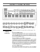
CHAPTER II: PLAYING THE DX100 1. DX100 Voice Memory Configuration The DX100 has three different voice memories which serve different purposes. They are: The 24-voice INTERNAL memory. This voice memory is used for quick selection of voices for performance, and it is to this memory that original voices you have edited or programmed are initially stored. Cassette LOAD and STORE operations are also carried out to and from the 24-voice INTERNAL memory.
mode, while the second group is accessed in the SHIFT mode (these modes will be described below. These voices may be selected and stored in the BANK or INTERNAL memories as desired. They can also be directly accessed and played using the PRESET SEARCH function. The chart below shows the overall DX100 voice memory configuration. The VOICE EDIT BUFFER is a special memory into which a voice is called when selected.
In this mode, you can play any of the voices currently in the DX100’s 24-voice INTERNAL memory individually. 3. The BANK PLAY Mode The BANK PLAY mode enables you to access the 96 BANK memory locations. These initially contain the first group of 96 voices from the 192-voice PRESET ROM. Using the SHIFT mode, however, you can also access the second group of presets while in the BANK PLAY mode. Later, you can store any voices you like in any order in the these BANKS.
4. The 192-Voice PRESET Memory The DX100 comes with 192 different pre-programmed voices in an internal ROM (Read Only Memory).These voiced can be loaded singly into the DX100's selectable 24-voice INTERNAL memory, or into any location in the DX100 bank memory.
PRESET SEARCH This function allows you to directly access the voices in the PRESET memory, in the order they appear in the PRESET memory. PRESET SEARCH is accessed in the FUNCTION mode. To enter the FUNCTION mode press the FUNCTION button. Then press any of the PRESET SEARCH selectors to access the corresponding voices (these are the same as the BANK A–D selectors used in the BANK PLAY mode).
CHAPTER III: THE FUNCTION MODE The FUNCTION mode permits access to four groups of functions: tuning functions, MIDI functions, memory management functions, and performance functions. In this chapter we’ll describe each of these functions; what they do and how they are programmed. 1. Accessing the FUNCTION Mode 2. Entering Function Data The FUNCTION mode is called by pressing the FUNCTION button. Individual parameters to be programmed are then called by pressing the appropriate voice button.
* Note that performance parameters 13 through 24 can be individually stored for each voice. They must therefore be stored in the appropriate INTERNAL RAM voice memory location after editing using the STORE function (see CHAPTER IV: VOICE PROGRAMMING, 4. Storing Voice Data). 13: POLY/MONO This function selects either the POLY or MONO note output mode. Voice programmed with the POLY mode permit simultaneous playing of up to 8 notes. In the MONO mode the DX100 acts as monophonic keyboard.
: PORTAMENTO MODE Two different portamento modes are available: Full Time Portamento and Fingered Portamento. When the POLY/MONO function is set to POLY (button 13), only the Full Time Portamento mode is accessible. In the MONO mode, you have a choice between the Full Time and Fingered portamento modes. (1) “Full T. Porta” (MONO and POLY modes): A conventional portamento effect in which portamento occurs whenever a new note is played.
LFO modulation can be made to modulate the pitch of the voice, producing a range of vibrato type effects. This function is used to set the maximum depth of pitch modulation which can be applied using the modulation wheel. The actual effect produced depends on the settings of the LFO parameters, these will be discussed in CHAPTER IV: VOICE PROGRAMMING. Note, however, that the appropriate voice PITCH MODULATION SENSITIVITY parameter must be set to a value higher than 0 for pitch modulation to be effective.
20: BREATH RANGE, PITCH This function is used to set the maximum depth of LFO pitch modulation that can be applied using the breath controller. The actual effect produced depends on the settings of the LFO parameters-these will be discussed in CHAPTER IV: VOlCE PROGRAMMING. Note, however, that the appropriate voice PITCH MODULATION SENSlTlVlTY parameter must be set to a value higher than 0 for pitch modulation to be effective.
23: BREATH RANGE, EG BIAS This function permits breath pressure applied to the BC-1 breath controller to directly control the amplitude or timbre of the voice, according to settings of the corresponding voice parameters which will be covered in CHAPTER IV. The LFO has no effect–only your breath pressure directly affects the amplitude or timbre of the voice. The data range is from 0 to 99. At 0, EG bias is OFF.
be used once after this function is called. Subsequent changes must be made using the DATA ENTRY slider and -1 /+1 buttons after the INTERNAL PLAY mode and KEY SHIFT function have been entered in succession. and KEY SHIFT function have been entered in succession. NOTE: The KEY SET function can not be individually programmed for each voice This section includes a single function: MASTER TUNE ADJ. 4. Tuning Functions 1: MASTER TUNE ADJ This is the DX100 MASTER TUNE function.
7: INIT VOICE This function sets all voice parameters in the voice edit buffer to their “initialized” values, permitting voice programming from an effectively neutral set of values—a “clean slate”. When this function is called, the LCD will read “Init. Voice?” Confirm your intention to initialize the voice edit buffer by pressing the +1 button.
for convenience and ease of selection during a performance, you would use the BANK EDIT function to place your 10 required voices in locations 1–10 in BANK A. There are 4 entire banks in the BANK memory. This means you can have 4 personally-arranged 24-voice groups to choose from, i.e., separate BANK for each set in a performance. To enter the BANK EDIT function, press the FUNCTION button, followed by the BANK EDIT button.
When this function is initially called, the LCD will read “Save to Tape ?” Confirm your intention to save the contents of the 24 voices to cassette tape by pressing the +1 button. The display will then read “Save ready?” At this point, reconfirm that the cassette recorder is set up properly, make sure a suitable blank tape is loaded into the cassette recorder, and start the recorder running in the RECORD mode. To begin the actual save operation, press the +1 button.
DATA ENTRY YES button again and start the cassette recorder running in the PLAY mode. Pressing the -1 button prior to the final step in the above process will abort the CASSETTE LOAD function. The DX100 will indicate each voice on the LCD as it is loaded. When the load function is completed, the LCD will read “Load Completed”. Stop the cassette recorder and turn the DX100’s MEMORY PROTECT function back ON. The LOAD function can be interrupted at any time by pressing the -1 button.
DX21 CASSETTE LOAD NOTE: If you have a voice set programmed on a Yamaha DX21 Digital Programmable Algorithm Synthesizer, these voices can be transferred from data cassette into the DX100. Of course, since the DX100 has 24 voice memories while the DX21 has 32, using the DX100 cassette LOAD operation will load only the first 24 voices of the DX21 32-voice set into the INTERNAL memory. The other voices (25—32) can be loaded using the DX100 LOAD SINGLE function.
is normally set to match the transmission or reception channel of the MlDI equipment to which the DX100 is connected. Data is entered using the DATA ENTRY control or -1/+1 buttons. Subsequent presses on the CHANNEL button call the “Omni: on/off”, “Midi R Ch=1–16”, and “Midi T Ch=1–16” selection modes. 4: CH INFO This is the MIDI channel information “button”. It turns transmission and reception of all MIDI BASIC EVENT DATA and OTHER EVENT DATA (with the exceptions noted below) ON or OFF.
CHAPTER IV: VOICE PROGRAMMING 1. The Basics of FM Synthesis Before you begin actually programming or editing your own voices, a basic understanding of how digital FM synthesis works will be necessary. In the following explanation, we will learn how the DX100’s FM voice generator produces complex voices. This information will help you to understand the process and make it easier for you to create and edit your own voices.
Operators do not have to be connected “vertically” in a modulator-carrier relationship, as shown above. The outputs of two operators can also be mixed-just as the stops in an organ are mixed. In this case the sounds are simply added together with no modulation effect. ALGORlTHMS We have seen two different ways that two operators may be combined. The DX100 uses four operators, offering many potential connection possibilities.
Most algorithms have multiple modulators and carriers. In one algorithm a given operator may be a carrier, while in the next it might function as a modulator–the only difference being how it is connected. In algorithm number 5 for example, there are two vertical stacks of two operators, and the outputs of the carriers in these stacks are connected in parallel (horizontally). Algorithm 5 has an equal number of modulators and carriers–two modulators and two carriers.
Still more variations can be achieved by changing the relative output levels between operators; the greater the level of the modulating operator, the more harmonics are present. FEEDBACK Note that every algorithm has one operator with a “feedback loop”–represented by a line from the output of the operator which feeds back to the input of the same operator. In effect, a feedback loop means that the operator is modulating itself.
content of the note changes (the timbre changes) from the time the note is initiated to the time it decays. Each of the 4 operators available in DX100 can be programmed with its own envelope. The envelope applied to a carrier will, generally, contribute to the overall volume envelope of the note, while an envelope applied to a modulator will contribute to the timbre envelope of the note. Here is a copy of the envelope diagram printed to the right of the algorithm diagrams on the DX100 panel.
2. The EDIT and COMPARE Modes To actually program or edit a voice, you need to enter the EDIT mode. This is done by pressing the EDIT/COMPARE button in the group of buttons. When the EDIT mode is activated, the LCD will indicate the operator ON/OFF status (the group of four 1s or 0S), the currently selected voice parameter, and the currently selected operator. The latter in the series applies only to parameters that deal with individual operators.
3. The Voice Parameters The following is a brief description of each available voice parameter, how it is programmed, and its effect. These parameters are selected by pressing the appropriately labelled (purple labels indicate voice parameters) button while the DX100 is in the EDIT mode. PB MODE: OPERATOR SELECT This switch (located immediately above the -1 DATA ENTRY button) selects the operator to be worked on. Only one operator can be selected at a time.
2: FEEDBACK Feedback can be applied to one operator in each algorithm. Pressing this button permits setting the amount (level) of feedback which will be applied. The feedback level range is from 0 to 7. At 0, feedback is OFF, and at 7 maximum feedback is applied. Data is entered via the DATA ENTRY slider or buttons. The LFO “LFO” stands for Low Frequency Oscillator. This oscillator is used to apply modulation effects such as tremolo or vibrato to the DX100 voices.
5: LFO DELAY Permits setting a delay of between 0 and approximately 10.7 seconds before the LFO modulation effect begins after a key is played. This is particularly useful for simulating brass instruments, human voice, etc., in which a vibrato effect is gradually applied after the note has been initiated. The data range is from 0 to 99. At 0 there is no delay, and a setting of 99 produces an initial delay of approximately 10.7 seconds, which slowly increases over a period of 10.7 seconds.
The beginning of the LFO cycle is normally synchronized with key-on timing. This parameter permits turning this synchronization on or off. All operators are affected simultaneously. When this parameter is on, the LFO cycle always begins from the peak of a positive half-cycle (90 degrees phase angle) when a key is played. This produces a clear, consistent attack on all notes. When LFO KEY SYNC is OFF, the LFO cycle starts from a random point when a key is played.
effects can be applied to the selected operators. A setting of 7 produces maximum sensitivity and therefore maximum effect depth. 12: KEY VELOCITY While the DX100 has no key velocity sensitivity of its own, its voice generators will accept key velocity data from an external MIDI controller keyboard which does have this feature.
ratio at a low operator level with even-ratio operators to add bite to a string sound and many other effects. The standard DX100 keyboard pitch is 8’; therefore, in terms of footage: 0.50 = 16’, 1.00 = 8’, and 2.00 = 4’. 14: DETUNE This parameter permits slight detuning of the selected operator in relation to the others, making it possible to create richer, fuller voice effects. If detune is applied to carriers, the result is a thick, multi-instrument effect.
The following EG curves show the parameters for some common instruments. PIANO E.G. CURVE ORGAN E.G. CURVE BRASS E.G. CURVE 20: OPERATOR OUT LEVEL Permits setting the output level of the selected operator. The data range is from 0 to 99. At 0, the operator is OFF. A setting of 99 produces maximum output level from the selected operator. Varying the output level of an operator functioning as a carrier results in a change in the overall level of the sound contributed to the voice by that operator.
4. Storing Voice Data If you have edited any of the above voice parameters and wish to store the new voice, you must use the STORE function BEFORE PRESSING ANY VOICE BUTTON AFTER EXITING THE EDIT OR FUNCTION MODES, and store the new data in one of the 24 INTERNAL memories. For this reason it is a good idea to have a free memory location ready before you begin editing.
If you choose to program a voice from scratch, you’ll need to have a clear memory location (or one containing a voice that you either don’t want or have already backed up on cassette tape, so that when you’ve completed programming the voice, you can save it). Since all editing is done in the separate voice edit buffer, nothing is erased while you are actually programming the voice. But when you save the new voice, whatever was in that memory location will be erased and replaced by the new data.
CHAPTER V: VOICE PROGRAMMING EXAMPLE In this section we’ll go through the steps in creating a fairly percussive electric piano voice from scratch. This simple example should help you understand the programming process. Initialize a Voice STEP 1: Enter the FUNCTION mode (press FUNCTION button) and call the MEMORY PROTECT function. Turn MEMORY PROTECT OFF. Call INIT VOICE function and press the YES button twice. This initializes the voice and automatically enters the EDIT mode.
STEP 4: Set the OP1 (carrier) EG Select the ENVELOPE GENERATOR AR parameter, and select operator 1 by pressing the OPERATOR SELECT button. We want an instantaneous attack, so AR should be set at 31. Select the D1R parameter and set to 10 for a relatively slow initial decay. Select the D1L parameter and set to 10. Select the D2R parameter and set to 8. Select the RR parameter and set to 8. Now play a note and listen to the volume envelope we’ve created. This is the basic form of the electric piano voice.
D1L = 0 D2R = 0 RR = 10 STEP 9: STEP 10: STEP 11: Copy OP3 (carrier) EG Parameters to OP4 (modulator) Hold down the EG COPY button and press the OPERATOR/AMS ON-OFF 4 button. Raise OP4 (modulator) Output Level Select OP4, select the OPERATOR OUTPUT LEVEL parameter and set it to 71. Set OP4 Frequency Ratio To get a metallic attack “ping,” we’ll set the OP4 output level frequence ratio to 7.00. With OP4 selected, press the OPERATOR FREQ RATIO button and set to 7.00.
STEP 15: Add Amplitude Modulation to OP2 As a final enhancement to our voice, let’s add just a touch of amplitude modulation to OP2—the main piano sound modulator. This will create a subtle chorus effect. Select the LFO WAVE parameter, set to triangle. Select the LFO SPEED parameter, set to 28. Select the AMD (Amplitude Modulation Depth) parameter, set to 52. Select the MODULATION SENSITIVITY, AMPLITUDE parameter, set to 1 for OP2 only (press the OPERATOR/AMS ON-OFF button). Now try the voice.
GENERAL SPECIFICATIONS Keyboard 49 keys, (Mini keybord) Sound Source FM Tone Generator (4 operators, 8 algorithms) Simultaneous Note Output 8 notes, reverse priority Internal Memory 24-voice internal RAM (alterable) 192-voice number bank (reading only) 96-voice number bank (alterable) Effects PITCH BLEND WHEEL, MODULATION, PORTAMENTO, SUSTAIN, KEY VELOCITY (reception only) Controls PITCH BEND, WHEEL, MODULATION WHEEL, VOLUME, LCD CONTRAST External Control Terminals BREATH CONTROL, FOOT SWITCH
MIDI DATA FORMAT 1.
2. Transmission Data All MIDI data is transmitted when the MIDI ON/OFF function is ON. The MIDI transmission channel is determined by the setting of the MIDI T CH function. 2-1. Channel Information 2-1-1 Channel Voice Message (1) Key On/Off Status Note. no. Velocity 1001nnnn(9n) 0kkkkkkk 01000000(40) 00000000(00) n=channel no. k=36(C1) ~ 84(C5) Key on Key off 1011nnnn(Bn) 0ccccccc 0vvvvvvv n=channel no. (2) Control Change Status Control no.
2-2 System Information 2-2-1 System Real-Time Message Active sensing Status 11111110(FE) Transmitted once approximately every 200 milliseconds 2-2-2 System Exclusive Message Transmitted only when MIDI SYS INFO is ON (1) Parameter Change Status ID no. Substatus/ch. no. Parameter group no. Parameter no. Data EOX 11110000(F0) 01000011(43) 0001 nnnn(1n) n=channel no.
Byte count 00000000(00) Data 0ddddddd Checksum EOX 0ddddddd 0eeeeeee 11110111(F7) 4096 bytes The data of 32 voices, including the 24 voices in RAM memory, will be transmitted if the YES key is pressed in response to the "MIDI Transmit?” display which appears when the SYS INFO key is pressed twice in the FUNCTION mode. The data for all 32 voices will also be transmitted when a format no. f=4 dump request is received. The transmitted data is shown in voice data table 5-1.
3.
4. Reception Data All MIDI data is received when the MIDI ON/OFF function is ON. When a specific MIDI receive channel has been selected using the MIDI R CH fuction, and the OMNl mode is OFF, MIDI data will be recieved only on the specified channel. MIDI data will be received on all channels when the OMNI mode is ON. 4-1. Channel Information 4-1-1 Channel Voice Message (1) Key Off Status Note no. Velocity 1000nnnn(8n) 0kkkkkkk 00000000(00) n=channel no.
Functions only on MSB data: MSB 00000000 01000000 01111111 Lowest value Center value Highest value 4-1-2 Channel Mode Message n=channel no. 1011nnnn 0ccccccc 0vvvvvvv Status Received whether MIDI CH INFO is ON or OFF V=0 V=1 V=0 C=123 C=126 C=127 All notes OFF MONO mode ON POLY mode ON 4-2 System Information 4-2-1 System Real-Time Message Active sensing Status 11111110(FE) within 300 milliseconds the MIDI receive buffer will be cleared and the currently output note will be turned OFF.
(3) 1 Voice Bulk Data Received only when MIDI SYS INFO is ON. The format is the same as for the transmitted 1 voice bulk data. The 93 voice data bytes are read into the voice edit buffer, replacing the current voice data. The 93 received data bytes are show in voice parameter table 5-2. CHORUS, FOOT VOLUME RANGE and PEG data are ignored. (4) 32 Voice Bulk Data Received only when MIDI SYS INFO is ON. The format is the same as for the transmitted 32 voice bulk data.
5-1. VOICE DATA (VMEM format) 5. System Exclusive Data Parameter no.
5-2. VOlCE PARAMETERS (VCED format) parameter no.
5-3. FUNCTION PARAMETERS Parameter no.
[ Digital Programmable Algorium Synthesizer] Model DX100 MIDI Implementation Chart Transmitted Function Date : 5/10, 1985 Version : 1.0 Recognized : : ...
VOICE/FUNCTION DATA DATA NAME : DATE : NUMBER : PROGRAMMER : 57
DATA NAME DATE : PROGRAMMER : No.
FCC INFORMATION (USA) While the following statements are provided to comply with FCC Regulations in the United States, the corrective measures listed below are applicable worldwide. This series of Yamaha professional music equipment uses frequencies that appear in the radio frequency range and if installed in the immediate proximity of some types of audio or video devices (within three meters), interference may occur.
YAMAHA Yamaha Corporation of America 6600 Orangethorpe Avenue, P.O.