
User Manual


23
System set-up
Once the Remote Antenna Receiver has been connected to the Base DSP unit,
connect that unit to the power mains and turn the switch on the front of the
unit to “1”. The unit will now power up. You will see messages on the front
screen providing information until the unit is operational. Once the Screen
with the VU screen is shown, and the Antenna symbol is constant, the system
is operational.
For additional system configuration instructions, see later sections describing
the different user interfaces in this manual.
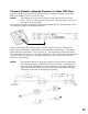
Analog Audio
The back panel of the Executive Elite 2 base unit provides two 3.5mm
Euroblock inputs and two 3.5mm Euroblock outputs, providing access to the
audio signal.
The Euroblock connectors included in the package are designed for easy
wiring. The three terminals (from left to right) correspond to positive +, negative
-, and shielded ground G.
To connect audio In/Out on the Base Station:
1. Use the screws on top of the connector to first open the terminals.
2. Insert an appropriate 3-conductor cable (2 conductors and shield) into the
terminals.
3. Tighten the screw to secure the cable.
4. Push the connector onto the pins centered under the desired input or
output port on the back of the Base DSP unit until firmly
secured.
The microphone output connectors need to be attached to the
line-level (0dBu) input connectors of the post-processing audio
equipment (mixer, DSP).
NOTE: Phantom power must be switched off on the mixer / DSP for the
input used to connect the Executive Elite. Phantom power might
cause damage to the Executive Elite inputs.
If back-channel audio uses the analog audio in, the Base DSP Unit input
connectors (also 0dBu) may be attached to the output channels of the post-
processing equipment.