68V15 Hyoshi 3/25/04 12:36 AM Page 1 F115D LF115D OWNER’S MANUAL Printed in Japan April 2004–1.0 × 1 ! Printed on recycled paper U.S.A.
68V15 Hyoshi 3/25/04 12:36 AM Page 2 EMU25060 ZMU01690 Read this owner’s manual carefully before operating your outboard motor.
Important manual information EMU25100 To the owner Thank you for choosing a Yamaha outboard motor. This Owner’s Manual contains information needed for proper operation, maintenance and care. A thorough understanding of these simple instructions will help you obtain maximum enjoyment from your new Yamaha. If you have any question about the operation or maintenance of your outboard motor, please consult a Yamaha dealer.
Table of contents General information .......................... 1 Identification numbers record........... 1 Outboard motor serial number .......... 1 Key number....................................... 1 Emission control information ............ 1 North American models..................... 1 Star labels ......................................... 2 Safety information ............................ 3 Important labels................................ 4 Warning labels ..................................
Table of contents control models) ............................. 34 Reverse (automatic reverse lock and power trim and tilt models)..... 34 Stopping engine ............................. 35 Procedure ....................................... 35 Trimming outboard motor............... 35 Adjusting trim angle ........................ 36 Adjusting boat trim .......................... 37 Tilting up and down ........................ 37 Procedure for tilting up .................... 38 Procedure for tilting down ...
General information EMU25170 Identification numbers record EMU25182 Outboard motor serial number The outboard motor serial number is stamped on the label attached to the port side of the clamp bracket or the upper part of the swivel bracket. Record your outboard motor serial number in the spaces provided to assist you in ordering spare parts from your Yamaha dealer or for reference in case your outboard motor is stolen. 1.
General information ZMU01699 ZMU04776 EMU25261 EMU25280 Manufactured date label This label is attached to the clamp bracket or the swivel bracket. One Star—Low Emission The one-star label identifies engines that meet the Air Resources Board’s 2001 exhaust emission standards. Engines meeting these standards have 75% lower emissions than conventional carbureted two-stroke engines. These engines are equivalent to the U.S. EPA’s 2006 standards for marine engines.
General information ● ZMU01703 ● EMU25300 Three Stars—Ultra Low Emission The three-star label identifies engines that meet the Air Resources Board’s 2008 exhaust emission standards. Engines meeting these standards have 65% lower emissions than One Star-Low-Emission engines. ● ● ● ZMU01704 EMU25361 Safety information ● ● ● 3 Before mounting or operating the outboard motor, read this entire manual. Reading it should give you an understanding of the motor and its operation.
General information of the road” on page 4. ● Stay informed about the weather. Check weather forecasts before boating. Avoid boating in hazardous weather. ● Tell someone where you are going: leave a Float Plan with a responsible person. Be sure to cancel the Float Plan when you return. ● Use common sense and good judgment when boating. Know your abilities, and be sure you understand how your boat handles under the different boating conditions you may encounter.
General information are waterway rules which apply when you are driving your boat. These rules are used internationally, and are also enforced by the United States Coast Guard and local agencies. You should be aware of these rules, and follow them whenever you encounter another vessel on the water. Several sets of rules prevail according to geographic location, but are all basically the same as the International Rules of the Road.
General information Meeting If you are meeting another power vessel head on, and are close enough to run the risk of collision, neither of you has the right-ofway! Both of you should alter course to avoid an accident. You should keep the other vessel on your port (left) side. This rule doesn’t apply if both of you will clear one another if you continue on your set course and speed. Overtaking If you are passing another vessel, you are the “Give-Way” vessel.
General information or trawls are considered to be “fishing vessels” under the International Rules. Vessels with trolling lines are not considered fishing vessels. Fishing vessels have the right-ofway regardless of position. Fishing vessels cannot, however, impede the passage of other vessels in narrow channels. Sailing vessel right-of-way Sailing vessels should normally be given the right-of-way. The exceptions to this are: 1.
General information ZMU01708 EMU25540 Fueling instructions EWM00010 WARNING GASOLINE AND ITS VAPORS ARE HIGHLY FLAMMABLE AND EXPLOSIVE! ● Do not smoke when refueling, and keep ● ● ● away from sparks, flames, or other sources of ignition. Stop engine before refueling. Refuel in a well-ventilated area. Refuel portable fuel tanks off the boat. Take care not to spill gasoline.
General information ● ● ● ● ● dry rags. Do not overfill the fuel tank. Tighten the filler cap securely after refueling. If you should swallow some gasoline, inhale a lot of gasoline vapor, or get gasoline in your eyes, get immediate medical attention. If any gasoline spills onto your skin, immediately wash with soap and water. Change clothing if gasoline spills on it. Touch the fuel nozzle to the filler opening or funnel to help prevent electrostatic sparks.
General information electric system could perform poorly or be overloaded, causing electric system damage. For electric start models, choose a battery which meets the following specifications. Yamaha dealers stock a range of propellers, and can advise you and install a propeller on your outboard that is best suited to your application. EMU25711 x Battery specifications Minimum cold cranking amps (CCA/ SAE): 380.0 A Minimum marine cranking amps (MCA/ ABYC): 502.
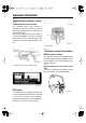
Basic components EMU25795 Main components NOTE: * May not be exactly as shown; also may not be included as standard equipment on all models. F115D, LF115D 1 9 2 2 10 11 12 14 15 16 17 13 3 8 4 7 5 6 18 ZMU04773 1. Top cowling 2. Top cowling lock lever(s) 3. Drain screw 4. Anti-cavitation plate 5. Trim tab (anode) 6. Propeller* 7. Cooling water inlet 8. Anode 9. Flushing device 10. Power trim and tilt switch 11. Remote control box (side mount type)* 12.
Basic components 1. Power trim and tilt switch 2. Remote control lever 3. Neutral interlock trigger 4. Neutral throttle lever 5. Main switch / choke switch 6. Engine stop lanyard switch 7. Throttle friction adjuster 1. Neutral “ ” 2. Forward “ ” 3. Reverse “ ” 4. Shift 5. Fully closed 6. Throttle 7. Fully open 1 2 4 F 2 6 4 5 N 1 R 3 4 6 5 2 7 3 7 ZMU04569 1. Remote control lever 2. Power trim and tilt switch 3. Free accelerator 4.
Basic components erator button and move the remote control lever. 2 3 1 1. Neutral interlock trigger EMU26211 Neutral throttle lever To open the throttle without shifting into either forward or reverse, put the remote control lever in the neutral position and lift the neutral throttle lever. ZMU04575 1. Fully open 2. Fully closed 3. Free accelerator NOTE: ● NOTE: The neutral throttle lever will operate only when the remote control lever is in neutral.
Basic components there is too much resistance, it could be difficult to move throttle lever or grip, which could result in an accident. ● ● to a secure place on your clothing, or your arm or leg while operating. Do not attach the lanyard to clothing that could tear loose. Do not route the lanyard where it could become entangled, preventing it from functioning. Avoid accidentally pulling the lanyard during normal operation. Loss of engine power means the loss of most steering control.
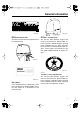
Basic components EMU26141 2. Lock plate Power trim and tilt switch on remote control or tiller handle EMU26090 Main switch The main switch controls the ignition system; its operation is described below. ● “ ” (off) With the main switch in the “ ” (off) position, the electrical circuits are off, and the key can be removed. ● “ ” (on) With the main switch in the “ ” (on) position, the electrical circuits are on, and the key cannot be removed.
Basic components while the boat is moving could increase the risk of falling overboard and could distract the operator, increasing the risk of collision with another boat or an obstacle. UP NOTE: ● ● On the dual engine control, the switch on the remote control grip controls both outboard motors at the same time. For instructions on using the power trim and tilt switches, see pages 35 and 37.
Basic components EMU26382 Top cowling lock lever (pull up type) 3 To remove the engine top cowling, pull up the lock lever(s) and lift off the cowling. When installing the cowling, check to be sure it fits properly in the rubber seal. Then lock the cowling by moving the lever(s) downward. 2 1 B A ZMU02525 1 1. Trim tab 2. Bolt 3. Cap ZMU04225 1.
Basic components 6 1 7 1 2 3 5 ZMU04256 1. Flushing device EMU26470 Tachometer This gauge shows the engine speed and has the following functions. 1 8 4 9 ZMU04185 1. Tachometer 2. Trim meter 3. Hour meter 4. Low oil pressure warning indicator 5. Overheat warning indicator 6. Water separator warning indicator 7. Engine trouble warning indicator 8. Set button 9.
Basic components indicator will flash. For further information on reading the indicator, see page 25. ECM00050 CAUTION: Do not continue to run the engine if the overheat warning indicator is on. Serious engine damage will occur. ZMU04754 EMU26521 Low oil pressure warning indicator If oil pressure drops too low, the warning indicator will start to blink. For further information, see page 26.
Basic components EMU26600 Speedometer (digital type) This gauge shows the boat speed. 1. Cap 2. Selector switch (for speed unit) 3. Selector switch (for fuel sensor) 1. Speedometer 2. Fuel gauge 3. Trip meter/clock/voltmeter 4. Warning indicator(s) EMU26610 Trim meter This gauge shows the trim angle of your outboard motor. NOTE: After the main switch is first turned on, all segments of the display come on as a test. After a few seconds, the gauge will change to normal operation.
Basic components ● the power trim and tilt switch. If the trim angle of your motor exceeds the trim operating range, the top segment on the trim meter display will blink. resets the trip counter to 0 (zero). NOTE: The total number of hours the engine has been run cannot be reset. EMU26690 Trip meter This gauge displays the distance the boat has traveled since the gauge was last reset. Press the “ ” (mode) button repeatedly until the indicator on the face of the gauge points to “ ” (trip).
Basic components display will begin blinking. Press the “ ” (mode) button until the desired minute is displayed. Press the “ ” (set) button again to start the clock. ZMU01745 EMU26720 Fuel warning indicator NOTE: The clock operates on battery power. Disconnecting the battery will stop the clock. Reset the clock after connecting the battery. EMU26710 Fuel gauge The fuel level is indicated by eight segments. When all segments are showing, the fuel tank is full.
Basic components vice has activated. For charging the battery, consult your Yamaha dealer. segments come on. EMU26750 Fuel flow meter The fuel flow meter displays the amount of fuel flow over a one hour period, at the current rate of engine operation. If twin engines are installed on your boat, the fuel flow meter displays the total fuel flow of both the port and starboard engines. It also displays “ ” (for port and starboard). 1.
Basic components until the indicator on the face of the gauge points to “ ” (economy). 1. Selector switch ZMU01752 ● The fuel consumption meter and fuel economy meter will indicate the same unit of measurement. EMU26760 Fuel consumption meter This gauge displays the total amount of fuel consumed since the gauge was last reset. Press the “ ” (mode) button repeatedly until the indicator on the face of the gauge points to total “ ” (total).
Basic components greater if the engines are of different year models. In addition, variations in propellers, even of the same basic dimensions of the same design, can also cause a slight variation in fuel consumption. NOTE: If the two engines’ speeds are not synchronized while cruising, they can be synchronized by adjusting trim angle or throttle.
Basic components ZMU02630 ZMU04227 ● The buzzer will sound. NOTE: ZMU03025 Dual engine drive users: Should the overheat warning system of one engine activate, the engine will slow down and the buzzer will sound. This will cause the other engine to slow down and the buzzer to sound. To switch off the warning activation on the engine not affected by overheating, turn off the main switch of the engine overheating.
Basic components ZMU04254 ● The buzzer will sound. ZMU02360 ON OFF START ON OFF START ZMU04584 If the warning system has activated, stop the engine as soon as it is safe to do so. Check the oil level and add oil as needed. If the oil level is correct, consult your Yamaha dealer. ECM00100 CAUTION: Do not continue to run the engine if the low oil pressure warning indicator is on. Serious engine damage could occur.
Operation EMU26901 Installation ECM00110 CAUTION: Incorrect engine height or obstructions to smooth water flow (such as the design or condition of the boat, or accessories such as transom ladders or depth finder transducers) can create airborne water spray while the boat is cruising. Severe engine damage may result if the motor is operated continuously in the presence of airborne water spray. NOTE: During water testing check the buoyancy of the boat, at rest, with its maximum load.
Operation ● board motor is affected by the boat/motor combination and the desired use. Test runs at different heights can help determine the optimum mounting height. Consult your Yamaha dealer or boat manufacturer for further information on determining the proper mounting height. For instructions on setting the trim angle of the outboard motor, see page 35. EMU30172 Breaking in engine 1.
Operation not working properly, have it inspected and repaired before operating the outboard motor. Otherwise an accident could occur. ECM00120 CAUTION: Do not start the engine out of water. Overheating and serious engine damage can occur. EMU27110 Fuel ● ● ● ● Check to be sure you have plenty of fuel for your trip. Make sure there are no fuel leaks or gasoline fumes. Check fuel line connections to be sure they are tight (if equipped Yamaha fuel tank or boat tank).
Operation EMU30021 EMU27450 Filling fuel EWM00060 WARNING Gasoline and its vapors are highly flammable and explosive. Keep away from sparks, cigarettes, flames, or other sources of ignition. 1. 2. 3. Remove the fuel tank cap. Carefully fill the fuel tank. Securely close the cap after filling the tank. Wipe up any spilled fuel.
Operation a secure place on your clothing, or your arm or leg. Then install the lock plate on the other end of the lanyard into the engine stop switch. EWM00120 WARNING ● ● EMU27490 Starting engine EMU27624 Electric start and remote control models 1. Place the remote control lever in “ ” (neutral). NOTE: The start-in-gear protection device prevents the engine from starting except when in neutral. N OFF ZMU04588 2.
Operation 3. Turn the main switch to “ possible to start the engine. The starter can also be damaged. If the engine will not start after 5 seconds of cranking, return the main switch to “ ” (on), wait 10 seconds, then crank the engine again. ” (on). NOTE: Dual engine users: When the main switch is turned on, the buzzer operates for a few seconds then stops automatically. The buzzer also operates if one of the engines stalls. 4.
Operation ZMU04229 EMU27740 Shifting N F EWM00180 WARNING Before shifting, make sure there are no swimmers or obstacles in the water near you. ECM00220 CAUTION: To change the boat direction or shifting position from forward to reverse or viceversa, first close the throttle so that the engine idles (or runs at low speeds). ZMU04597 EMU27784 Reverse (automatic reverse lock and power trim and tilt models) EWM00190 EMU27763 Forward (tiller handle and remote control models) Tiller control models 1.
Operation 2. N R 3. 4. After stopping the engine, disconnect the fuel line if there is a fuel joint on the outboard motor. Tighten the air vent screw on the fuel tank cap (if equipped). Remove the key if the boat will be left unattended. NOTE: ZMU04598 EMU27820 Stopping engine Before stopping the engine, first let it cool off for a few minutes at idle or low speed. Stopping the engine immediately after operating at high speed is not recommended. EMU27844 Procedure 1.
Operation the boat begins to feel unstable or is hard to steer, slow down and/or readjust the trim angle. bottom engine cowling (if equipped) only when the boat is at a complete stop with the engine off. Adjust the outboard motor trim angle using the power trim and tilt switch. 1. Power trim and tilt switch 1 1 DN UP ZMU04258 1.
Operation To raise the bow (trim-out), press the switch “ ” (up). To lower the bow (trim-in), press the switch “ ” (down). Make test runs with the trim set to different angles to find the position that works best for your boat and operating conditions. the propeller to ventilate, which reduces performance further, and the boat may “porpoise” (hop in the water), which could throw the operator and passengers overboard.
Operation if the boat is moored in shallows, the outboard motor should be tilted up to protect the propeller and casing from damage by collision with obstructions, and also to reduce salt corrosion. N EWM00220 WARNING Be sure all people are clear of the outboard motor when tilting up and down, also be careful not to pinch any body parts between the drive unit and engine bracket. ZMU03196 N EWM00250 WARNING Leaking fuel is a fire hazard.
Operation sure. 5. UP Models equipped with trim rods: Once the outboard motor is supported with the tilt support lever, press the power trim and tilt switch “ ” (down) to retract the trim rods. ECM00250 CAUTION: ZMU04602 UP Be sure to retract the trim rods completely during mooring. This protects the rods from marine growth and corrosion which could damage the power trim and tilt mechanism. ZMU04232 4.
Operation DN ZMU03453 3. Push the power tilt / power trim and tilt switch “ ” (down) to lower the outboard motor to the desired position. ZMU04255 EMU28060 Cruising in shallow water The outboard motor can be tilted up partially to allow operation in shallow water. EMU28090 DN Power trim and tilt models / power tilt models UP DN The outboard motor can be tilted up partially to allow operation in shallow water.
Operation N UP ZMU03525 N ZMU04602 UP ZMU04588 2. Slightly tilt the outboard motor up to the desired position using the power trim / tilt switch. ZMU04235 3. To return the outboard motor to the normal running position, press the power trim / tilt switch and slowly tilt the outboard motor down.
Maintenance EMU28215 Specifications Dimension: Overall length: 825 mm (32.5 in) Overall width: 498 mm (19.6 in) Overall height L: F115TR 1609 mm (63.3 in) Overall height X: 1736 mm (68.3 in) Transom height L: F115TR 516 mm (20.3 in) Transom height X: 643 mm (25.3 in) Weight (without propeller) L: F115TR 183.0 kg (403 lb) Weight (without propeller) X: 188.0 kg (414 lb) Performance: Full throttle operating range: 5000–6000 r/min Maximum output: 84.
Maintenance Wet sump Engine oil quantity (excluding oil filter): 4.3 L (4.55 US qt) (3.78 Imp.qt) Recommended gear oil: Hypoid gear oil SAE#90 Gear oil quantity: F115TR 760.0 cm3 (25.70 US oz) (26.81 Imp.oz) LF115TR 715.0 cm3 (24.18 US oz) (25.17 Imp.oz) Tightening torque for engine: Spark plug: 25.0 Nm (18.4 ft-lb) (2.55 kgf-m) Propeller nut: 55.0 Nm (40.6 ft-lb) (5.61 kgf-m) Engine oil drain bolt: 28.0 Nm (20.7 ft-lb) (2.86 kgf-m) Engine oil filter: 18.0 Nm (13.3 ft-lb) (1.
Maintenance cooling water inlet. lowing procedures. ECM01080 CAUTION: ● ● ● To prevent problems which can be caused by oil entering the cylinder from the sump, keep the outboard motor in the attitude shown when transporting and storing it. If storing or transporting the outboard motor on its side (not upright), put it on a cushion after draining the engine oil.
Maintenance “Yamaha Silicone Protectant” (Part No. LUB-SILCNE-13-00). parts while the engine is running. 6. 7. 8. 9. Run the engine at a fast idle for 10–15 minutes in neutral position while supplying fresh water. Just prior to turning off the engine, quickly spray “Yamaha Stor-Rite Engine Fogging Oil” (Part No. LUB-STRRT-1200) alternately into each carburetor/ each intake manifold. When properly done, the engine will smoke excessively and almost stall.
Maintenance equipment, lighted cigarettes, and so on.) ● DO NOT SMOKE when charging or handling batteries. KEEP BATTERIES AND ELECTROLYTIC FLUID OUT OF REACH OF CHILDREN. Batteries vary among manufacturers. Therefore the following procedures may not always apply. Consult your battery manufacturer’s instructions. Procedure 1. Disconnect and remove the battery from the boat. Always disconnect the black negative cable first to prevent the risk of shorting. 2. Clean the battery casing and terminals.
Maintenance instead of cooling the engine, which can cause serious overheating. Be sure the connector is tightened securely on the fitting after flushing the engine. NOTE: ● ● When flushing the engine with the boat in the water, tilting up the outboard motor until it is completely out of the water will achieve better results. For cooling system flushing instructions, see page 43. EMU28450 Cleaning the outboard motor After use, wash the exterior of the outboard motor with fresh water.
Maintenance EMU30560 Maintenance chart NOTE: ● ● ● ● Refer to the sections in this chapter for explanations of each owner-specific action. The maintenance cycle on these charts assume usage of 200 hours per year. Maintenance frequency should be adjusted according to usage conditions. Disassembly or repairs may be necessary depending on the outcome of maintenance checks.
Maintenance Initial Item Actions Throttle link / throttle cable / throttle pick-up timing Inspection / adjustment Water pump Inspection Engine oil Inspection / change Oil filter (cartridge) Change Spark plug(s) Timing belt 10 hours (1 month) Every 50 hours (3 months) 100 hours (6 months) 200 hours (1 year) Cleaning / adjustment / replacement Inspection / replacement NOTE: When operating in salt water, turbid or muddy water, the engine should be flushed with clean water after each use.
Maintenance EMU28931 Greasing Yamaha marine grease (Water resistant grease) F115D, LF115D ZMU04266 EMU28951 Cleaning and adjusting spark plug EWM00560 WARNING When removing or installing a spark plug, be careful not to damage the insulator. A damaged insulator could allow external sparks, which could lead to explosion or fire. The spark plug is an important engine component and is easy to inspect. The condition of the spark plug can indicate something about the condition of the engine.
Maintenance sources of ignition. EWM00910 WARNING Leaking fuel can result in fire or explosion. ● Check for fuel leakage regularly. ● If any fuel leakage is found, the fuel system must be repaired by a qualified mechanic. Improper repairs can make the outboard unsafe to operate. 1. Spark plug gap 2. Spark plug I.D. mark (NGK) Spark plug gap: 1.0–1.1 mm (0.039–0.043 in) Check the fuel lines for leaks, crack, or malfunction.
Maintenance 2. EMU28980 Inspecting fuel filter EWM00310 3. WARNING Gasoline is highly flammable, and its vapors are flammable and explosive. ● If you have any question about properly doing this procedure, consult your Yamaha dealer. ● Do not perform this procedure on a hot or running engine. Allow the engine to cool. ● There will be fuel in the fuel filter. Keep away from sparks, cigarettes, flames or other sources of ignition. ● This procedure will allow some fuel to spill. Catch fuel in a rag.
Maintenance ● parts while the engine is running. 2-hp models: The propeller rotates whenever the engine is running. Do not move the throttle control lever from the start position during warm-up. The boat could unexpectedly start to move, which could result in an accident. ECM00490 CAUTION: This procedure must be performed while the outboard motor is in the water. A flushing attachment or test tank can be used.
Maintenance Then tighten 1/4 to 1/2 turn more. Tighten the drain screw to the correct torque with a torque wrench as soon as possible. 4. Recommended engine oil: 4-stroke outboard motor oil Engine oil quantity (excluding oil filter): 4.3 L (4.55 US qt) (3.78 Imp.qt) ZMU04270 2. Add the correct amount of oil through the filler hole. Install the filler cap. Prepare a suitable container that holds a larger amount than the engine oil capacity.
Maintenance specified level if it is above the upper mark. EMU29130 Water leakage Start the engine and check that no water leaks from the joints between the exhaust cover, cylinder head, and body cylinder. EMU29140 Engine oil leakage Check for oil leaks on the around the engine. NOTE: If any leaks are found, consult your Yamaha dealer. ZMU02058 EMU29153 7. Dispose of used oil according to local regulations. NOTE: ● ● For more information on the disposal of used oil, consult your Yamaha dealer.
Maintenance NOTE: 2. Trim rods 3. Tilt support lever 4. Consult your Yamaha dealer if any operation is abnormal. Use the tilt support lever to lock the motor in the up position. Operate the tilt down switch briefly so the motor is supported by the tilt support lever. 1 ZMU02634 1. Tilt support lever 5. 6. Check that the tilt rod and trim rods are free of corrosion or other flaws. Activate the tilt-down switch until the trim rods have retracted completely into the cylinders.
Maintenance EMU29193 Removing the propeller 1. 2. Straighten the cotter pin and pull it out using a pair of pliers. Remove the propeller nut, washer, and spacer (if equipped). ZMU01897 Checkpoints ● Check each of the propeller blades for wear, erosion from cavitation or ventilation, or other damage. ● Check the propeller shaft for damage. ● Check the splines / shear pin for wear or damage. ● Check for fish line tangled around the propeller shaft. 1. Cotter pin 2. Propeller nut 3. Washer 4. Spacer 5.
Maintenance ● 1. 2. 3. 4. could be damaged. Be sure to use a new cotter pin and bend the ends over securely. Otherwise the propeller could come off during operation and be lost. Apply Yamaha marine grease or a corrosion resistant grease to the propeller shaft. Install the thrust washer and propeller on the propeller shaft. Install the spacer and washer. Tighten the propeller nut to the specified torque. Align the propeller nut with the propeller shaft hole.
Maintenance sition, and using a flexible or pressurized filling device, inject the gear oil into the gear oil drain screw hole. Recommended gear oil: Hypoid gear oil SAE#90 Gear oil quantity: F115TR 760.0 cm3 (25.70 US oz) (26.81 Imp.oz) LF115TR 715.0 cm3 (24.18 US oz) (25.17 Imp.oz) anodes on equipped models. Consult a Yamaha dealer for inspection and replacement of internal anodes attached to the power unit. ZMU01901 ZMU03274 6. 7.
Maintenance dling or working near batteries. Antidote (EXTERNAL): ● SKIN - Flush with water. ● EYES - Flush with water for 15 minutes and get immediate medical attention. Antidote (INTERNAL): ● Drink large quantities of water or milk followed by milk of magnesia, beaten egg, or vegetable oil. Get immediate medical attention. Batteries also generate explosive hydrogen gas; therefore, you should always follow these preventive measures: ● Charge batteries in a well-ventilated area.
Maintenance ● when installing the battery and disconnect the black battery cable first when removing it. Otherwise, the electrical parts can be damaged. The electrical contacts of the battery and cables must be clean and properly connected, or the battery will not start the engine. Connect the red battery cable to the POSITIVE (+) terminal first. Then connect the black battery cable to the NEGATIVE (-) terminal. EMU29400 Coating the boat bottom A clean hull improves boat performance.
Trouble Recovery EMU29422 Troubleshooting A problem in the fuel, compression, or ignition systems can cause poor starting, loss of power, or other problems. This section describes basic checks and possible remedies, and covers all Yamaha outboard motors. Therefore some items may not apply to your model. If your outboard motor requires repair, bring it to your Yamaha dealer. If the engine trouble warning indicator is flashing, consult your Yamaha dealer. Starter will not operate. Q.
Trouble Recovery Q. Is fuel system obstructed? A. Check for pinched or kinked fuel line or other obstructions in fuel system. Q. Is fuel contaminated or stale? A. Fill tank with clean, fresh fuel. Q. Is fuel filter clogged? A. Clean or replace filter. Q. Have ignition parts failed? A. Have serviced by a Yamaha dealer. Q. Has warning system activated? A. Find and correct cause of warning. Q. Is spark plug gap incorrect? A. Inspect and adjust as specified. Q. Is ignition wiring damaged or poorly connected? A.
Trouble Recovery A. Have serviced by a Yamaha dealer. Q. Is load on boat improperly distributed? A. Distribute load to place boat on an even plane. Q. Are weeds or other foreign matter tangled on gear housing? A. Remove foreign matter and clean lower unit. Q. Is water pump or thermostat faulty? A. Have serviced by a Yamaha dealer. Q. Is fuel system obstructed? A. Check for pinched or kinked fuel line or other obstructions in fuel system. Q. Is there excess water in fuel filter cup? A. Drain filter cup.
Trouble Recovery board motor unsafe to operate. Q. Is heat range of spark plug incorrect? A. Inspect spark plug and replace it with recommended type. If the outboard motor hits an object in the water, follow the procedure below. Q. Is high pressure fuel pump drive belt broken? A. Have serviced by a Yamaha dealer. Q. Is engine not responding properly to shift lever position? A. Have serviced by a Yamaha dealer. Engine vibrates excessively. Q. Is propeller damaged? A. Have propeller repaired or replaced.
Trouble Recovery 3 4 2 EMU29480 Replacing fuse 2 1 If the fuse has blown on an electric start model, remove the electrical cover, open the fuse holder, and replace the fuse with a new one of the proper amperage. 5 EWM00630 WARNING Be sure to use the specified fuse. An incorrect fuse or a piece of wire could allow excessive current flow. This could cause electric system damage and a fire hazard. NOTE: Consult your Yamaha dealer if the new fuse immediately blows again. ZMU04279 1.
Trouble Recovery of a discharged battery or a failure with the power trim and tilt unit/the power tilt, the engine can be tilted manually. 1. Loosen the manual valve screw by turning it counterclockwise until it stops. ● ● ● 1 ZMU03464 1. Manual valve screw 2. Put the engine in the desired position, then tighten the manual valve screw by turning it clockwise.
Trouble Recovery OFF ON START ZMU04250 3. 4. Lift up the rear of flywheel cover and pull it forward to remove it. Prepare the engine for starting. For further information, see page 32. Be sure the engine is in neutral and that the engine stop switch lanyard lock plate is attached to the engine stop switch. The main switch must be “ ” (on). ZMU01906 5. 6. 7. 8. 9. Insert the knotted end of the emergency starter rope into the notch in the flywheel rotor and wind the rope around the flywheel clockwise.
Trouble Recovery dure below in order to minimize engine damage. EMU29790 Procedure 1. 2. 3. 4. 5. Thoroughly wash away mud, salt, seaweed, and so on, with fresh water. Remove the spark plugs and face the spark plug holes downward to allow any water, mud, or contaminants to drain. Drain the fuel from the vapor separator, fuel filter, and fuel line. Feed fogging oil or engine oil through the intake manifold and spark plug holes while cranking with the emergency starter rope.
Consumer information EMU29811 Important warranty information for U.S.A.
Consumer information 71
Consumer information EMU29830 YAMAHA MOTOR CORPORATION, U.S.A.
Consumer information 73
Consumer information EMU29840 IMPORTANT WARRANTY INFORMATION IF YOU USE YOUR YAMAHA OUTSIDE U.S.A.
68V15 Hyoshi 3/25/04 12:36 AM Page 1 F115D LF115D OWNER’S MANUAL Printed in Japan April 2004–1.0 × 1 ! Printed on recycled paper U.S.A.
Warranty card 2/27/02 11:47 AM Page 1 OUTBOARD MOTOR WARRANTY REGISTRATION ENREGISTREMENT DE LA GARANTIE DU MOTEUR HORS-BORD Please complete and mail this card. This information is necessary to accurately register your unit for warranty. Veuillez signer ci-dessous pour attester que le montage et l’inspection ont été faits dans le respect des directives d’inspection et que la marche à suivre pour la garantie et l’entretien a été expliquée à l’acheteur au détail.
Warranty card 2/27/02 11:47 AM Page 2 PLACE POSTAGE HERE ATTN: WARRANTY DEPARTMENT