F200 LF200 F225 LF225 OWNER’S MANUAL U.S.A.
U69J17E0.book Page 1 Tuesday, March 7, 2006 10:00 AM ZMU01690 Read this owner’s manual carefully before operating your outboard motor.
U69J17E0.book Page 1 Tuesday, March 7, 2006 10:00 AM Important manual information EMU31280 To the owner Thank you for choosing a Yamaha outboard motor. This Owner’s Manual contains information needed for proper operation, maintenance and care. A thorough understanding of these simple instructions will help you obtain maximum enjoyment from your new Yamaha. If you have any question about the operation or maintenance of your outboard motor, please consult a Yamaha dealer.
U69J17E0.book Page 1 Tuesday, March 7, 2006 10:00 AM Table of contents General information .......................... 1 Identification numbers record .......... 1 Outboard motor serial number ........... 1 Key number ........................................ 1 Emission control information ........... 1 North American models...................... 1 Star labels .......................................... 2 Safety information ........................... 3 Important labels...............................
U69J17E0.book Page 2 Tuesday, March 7, 2006 10:00 AM Table of contents Filling fuel ...................................... 38 Ring Free Fuel Additive.................... 38 Operating engine........................... 38 Feeding fuel...................................... 38 Starting engine ................................. 39 Warming up engine ....................... 40 Electric start models ......................... 40 Shifting .......................................... 41 Braking ......................
U69J17E0.book Page 3 Tuesday, March 7, 2006 10:00 AM Table of contents Consumer information.................... 79 Important warranty information for U.S.A. and Canada ............... 79 YAMAHA MOTOR CORPORATION, U.S.A. FOUR-STROKE OUTBOARD MOTOR THREE-YEAR LIMITED WARRANTY ............... 81 IMPORTANT WARRANTY INFORMATION IF YOU USE YOUR YAMAHA OUTSIDE THE USA OR CANADA .............
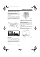
U69J17E0.book Page 1 Tuesday, March 7, 2006 10:00 AM General information EMU25170 Identification numbers record EMU25183 Outboard motor serial number The outboard motor serial number is stamped on the label attached to the port side of the clamp bracket. Record your outboard motor serial number in the spaces provided to assist you in ordering spare parts from your Yamaha dealer or for reference in case your outboard motor is stolen. 1.
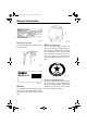
U69J17E0.book Page 2 Tuesday, March 7, 2006 10:00 AM General information 1. Star labels location EMU25262 Manufactured date label This label is attached to the clamp bracket or the swivel bracket. EMU25280 One Star—Low Emission The one-star label identifies engines that meet the Air Resources Board’s 2001 exhaust emission standards. Engines meeting these standards have 75% lower emissions than conventional carbureted two-stroke engines. These engines are equivalent to the U.S.
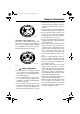
U69J17E0.book Page 3 Tuesday, March 7, 2006 10:00 AM General information ● ● ZMU01703 EMU25300 Three Stars—Ultra Low Emission The three-star label identifies engines that meet the Air Resources Board’s 2008 exhaust emission standards. Engines meeting these standards have 65% lower emissions than One Star-Low-Emission engines. ● ● ● ZMU01704 ● EMU25362 Safety information ● ● ● Before mounting or operating the outboard motor, read this entire manual.
U69J17E0.book Page 4 Tuesday, March 7, 2006 10:00 AM General information Know the marine laws and regulations where you will be boating—and obey them. For basic boating rules, see “Rules of the road” on page 5. ● Stay informed about the weather. Check weather forecasts before boating. Avoid boating in hazardous weather. ● Tell someone where you are going: leave a Float Plan with a responsible person. Be sure to cancel the Float Plan when you return. ● Use common sense and good judgment when boating.
U69J17E0.book Page 5 Tuesday, March 7, 2006 10:00 AM General information EMU25413 Label (counter rotation models) EWM01281 WARNING Use only a counterclockwise rotation propeller with this engine. Counterclockwise propellers are marked with a letter “L” after the size indication. The wrong type of propeller could cause the boat to go in an unexpected direction, which could lead to an accident.
U69J17E0.book Page 6 Tuesday, March 7, 2006 10:00 AM General information Crossing: (you are traveling across the other vessel’s path) Overtaking: (you are passing or being passed by another vessel) In the following illustration, your boat is in the center. You should give the right-of-way to any vessels shown in white area (you are the Give-Way vessel). Any vessels in the shaded area must yield to you (they are the Give-Way vessels). Both you and the meeting vessel must alter course to avoid each other.
U69J17E0.book Page 7 Tuesday, March 7, 2006 10:00 AM General information vessels, the operator should sound a prolonged blast on the whistle (4 to 6 seconds). If another vessel is around the bend, it too should sound the whistle. Even if no reply is heard, however, the vessel should still proceed around the bend with caution. If you navigate such waters with your boat, you will need to carry a portable air horn, available from local marine supply stores.
U69J17E0.book Page 8 Tuesday, March 7, 2006 10:00 AM General information ZMU01708 EMU25540 Fueling instructions ● EWM00010 WARNING GASOLINE AND ITS VAPORS ARE HIGHLY FLAMMABLE AND EXPLOSIVE! 8 ● ● Do not smoke when refueling, and keep away from sparks, flames, or other sources of ignition. Stop engine before refueling. Refuel in a well-ventilated area. Refuel portable fuel tanks off the boat.
U69J17E0.book Page 9 Tuesday, March 7, 2006 10:00 AM General information ● ● ● ● ● ● Take care not to spill gasoline. If gasoline spills, wipe it up immediately with dry rags. Do not overfill the fuel tank. Tighten the filler cap securely after refueling. If you should swallow some gasoline, inhale a lot of gasoline vapor, or get gasoline in your eyes, get immediate medical attention. If any gasoline spills onto your skin, immediately wash with soap and water. Change clothing if gasoline spills on it.
U69J17E0.book Page 10 Tuesday, March 7, 2006 10:00 AM General information ZMU01710 EMU25700 Battery requirement ECM01060 CAUTION: Do not use a battery that does not meet the specified capacity. If a battery which does not meet specifications is used, the electric system could perform poorly or be overloaded, causing electric system damage. damage the motor. Engine speed depends on the propeller size and boat load.
U69J17E0.book Page 11 Tuesday, March 7, 2006 10:00 AM General information For instructions on propeller removal and installation, see page 64. EMU25770 Start-in-gear protection Yamaha outboard motors or Yamaha-approved remote control units are equipped with start-in-gear protection device(s). This feature permits the engine to be started only when it is in neutral. Always select neutral before starting the engine.
U69J17E0.book Page 12 Tuesday, March 7, 2006 10:00 AM Basic components EMU25799 Main components NOTE: * May not be exactly as shown; also may not be included as standard equipment on all models. 1. Top cowling 2. Anti-cavitation plate 3. Trim tab (anode) 4. Propeller* 5. Cooling water inlet 6. Clamp bracket 7. Water separator 8. Top cowling lock lever(s) 9. Power trim and tilt switch 10.Flushing device 11.Remote control box (side mount type)* 12.Remote control box (binnacle mount type)* 13.
U69J17E0.book Page 13 Tuesday, March 7, 2006 10:00 AM Basic components 1 2 3 4 5 6 ZMU05429 1. 2. 3. 4. 5. 6. Tachometer unit (Square type)* Tachometer unit (Round type)* Speedometer unit (Square type)* Speed & fuel meter unit (Square type)* Speed & fuel meter unit (Round type)* Fuel management meter (Square type)* EMU26180 Remote control The remote control lever actuates both the shifter and the throttle. The electrical switches are mounted on the remote control box. 1. 2. 3. 4. 5. 6. 7.
U69J17E0.book Page 14 Tuesday, March 7, 2006 10:00 AM Basic components 1 F 2 2 6 4 4 N 1 5 7 3 7 ZMU04569 Remote control lever Power trim and tilt switch Free accelerator Throttle friction adjuster EMU26190 Remote control lever Moving the lever forward from the neutral position engages forward gear. Pulling the lever back from neutral engages reverse. The engine will continue to run at idle until the lever is moved about 35° (a detent can be felt).
U69J17E0.book Page 15 Tuesday, March 7, 2006 10:00 AM Basic components ● NOTE: The neutral throttle lever will operate only when the remote control lever is in neutral. The remote control lever will operate only when the neutral throttle lever is in the closed position. ● After the button is pushed, the throttle begins to open after the remote control lever is moved at least 35°. After using the free accelerator, return the remote control lever to the neutral position.
U69J17E0.book Page 16 Tuesday, March 7, 2006 10:00 AM Basic components NOTE: The engine cannot be started with the lock plate removed. ZMU04646 When constant speed is desired, tighten the adjuster to maintain the desired throttle setting. EMU25990 Engine stop lanyard switch The lock plate must be attached to the engine stop switch for the engine to run. The lanyard should be attached to a secure place on the operator’s clothing, or arm or leg.
U69J17E0.book Page 17 Tuesday, March 7, 2006 10:00 AM Basic components With the main switch in the “ ” (start) position, the starter motor turns to start the engine. When the key is released, it returns automatically to the “ ” (on) position. EMU26151 Power trim and tilt switch on bottom engine cowling OFF ON START OFF The power trim and tilt switch is located on the side of the bottom engine cowling. Pressing the switch “ ” (up) trims the outboard motor up, then tilts it up.
U69J17E0.book Page 18 Tuesday, March 7, 2006 10:00 AM Basic components EWM00840 NOTE: For instructions on using the power trim and tilt switch, see page 45. EMU26161 Power trim and tilt switches (twin binnacle type) The power trim and tilt system adjusts the outboard motor angle in relation to the transom. Pushing the switch “ ” (up) trims the outboard motor up, then tilts it up. Pressing the switch “ ” (down) tilts the outboard motor down and trims it down.
U69J17E0.book Page 19 Tuesday, March 7, 2006 10:00 AM Basic components 3. Cap EMU26340 Tilt support lever for power trim and tilt or hydro tilt model To keep the outboard motor in the tilted up position, lock the tilt support lever to the clamp bracket. EMU26460 Flushing device This device is used to clean the cooling water passages of the motor using a garden hose and tap water. ZMU01864 NOTE: For details on usage, see page 54.
U69J17E0.book Page 20 Tuesday, March 7, 2006 10:00 AM Basic components ● If the warning system has activated, stop the engine and consult a Yamaha dealer immediately. EMU31410 Digital tachometer The tachometer shows the engine speed and has the following functions. NOTE: All segments of the display will light momentarily after the main switch is turned on and will return to normal thereafter.
U69J17E0.book Page 21 Tuesday, March 7, 2006 10:00 AM Basic components ECM00020 CAUTION: ● ● Do not continue to run the engine if the low oil pressure warning indicator is on and the engine oil level is lower. Serious engine damage will occur. The low oil pressure warning indicator does not indicate the engine oil level. Use the oil dipstick to check the remaining oil quantity. For further information, see page 37. 1 ZMU01737 1.
U69J17E0.book Page 22 Tuesday, March 7, 2006 10:00 AM Basic components NOTE: The speedometer displays km/h, mph, or knots, according to operator preference. Select the desired unit of measurement by setting the selector switch on the back of the gauge. See the illustration for settings. ZMU01740 EMU26650 Hour meter (digital type) This meter shows the number of hours the engine has been run. It can be set to show the total number of hours or the number of hours for the current trip.
U69J17E0.book Page 23 Tuesday, March 7, 2006 10:00 AM Basic components EMU26690 Trip meter This gauge displays the distance the boat has traveled since the gauge was last reset. Press the “ ” (mode) button repeatedly until the indicator on the face of the gauge points to “ ” (trip). To reset the trip meter to zero, press the “ ” (set) and “ ” (mode) buttons at the same time. NOTE: The clock operates on battery power. Disconnecting the battery will stop the clock.
U69J17E0.book Page 24 Tuesday, March 7, 2006 10:00 AM Basic components ZMU01745 EMU26720 Fuel warning indicator If the fuel level decreases to one segment, the fuel level warning segment will begin to blink. ECM00880 CAUTION: 1. Low battery indicator EMU26740 Fuel management meter The fuel management meter shows the state of the fuel consumption while the engine is running. Do not continue to operate the engine with full throttle if a warning device has activated.
U69J17E0.book Page 25 Tuesday, March 7, 2006 10:00 AM Basic components EMU26750 Fuel flow meter The fuel flow meter displays the amount of fuel flow over a one hour period, at the current rate of engine operation. If twin engines are installed on your boat, the fuel flow meter displays the total fuel flow of both the port and starboard engines. It also displays “ ” (for port and starboard). 1. Selector switch ● The fuel consumption meter and fuel economy meter will indicate the same unit of measurement.
U69J17E0.book Page 26 Tuesday, March 7, 2006 10:00 AM Basic components even of the same basic dimensions of the same design, can also cause a slight variation in fuel consumption. EMU26780 Twin-engine speed synchronizer ZMU01752 NOTE: If twin engines are installed on your boat, the gauge will only display the total fuel economy of both engines.
U69J17E0.book Page 27 Tuesday, March 7, 2006 10:00 AM Basic components EMU31680 NOTE: Tachometer unit If the two engines’ speeds are not synchronized while cruising, they can be synchronized by adjusting trim angle or throttle. The tachometer shows the engine revolutions per minute.
U69J17E0.book Page 28 Tuesday, March 7, 2006 10:00 AM Basic components Preoperation checks Place the gear shift lever in neutral and turn the main switch to “ ” (on). After all the displays come on and the total hour display comes on, the gauge will change to normal operation. If the buzzer sounds and the water separator warning indicator blinks, consult your Yamaha dealer immediately. 6. Water detection warning indicator 7. Battery voltage 8. Oil pressure (4-stroke models) NOTE: 1 2 ZMU05417 1.
U69J17E0.book Page 29 Tuesday, March 7, 2006 10:00 AM Basic components vice has activated while the appropriate engine oil quantity is maintained, consult your Yamaha dealer. ECM01590 CAUTION: ● ECM01600 CAUTION: Do not continue to run the engine if the low oil pressure warning device has activated. Serious engine damage will occur. Overheat warning If the engine temperature rises too high while cruising, the overheat warning indicator will start to blink.
U69J17E0.book Page 30 Tuesday, March 7, 2006 10:00 AM Basic components ECM00910 CAUTION: Gasoline mixed with water could cause damage to the engine. port soon if the low battery voltage warning device has activated. For charging the battery, consult your Yamaha dealer. Engine trouble warning This indicator will blink when the engine malfunctions while cruising. Get back to the port soon and consult a Yamaha dealer immediately.
U69J17E0.book Page 31 Tuesday, March 7, 2006 10:00 AM Basic components 1 1 2 2 3 ZMU05432 1. Set button 2. Mode button ZMU05435 1. Speedometer 2. Fuel meter 3. Multifunction display 1 NOTE: After the main switch is first turned on, all the displays come on as a test. After a few seconds, the gauge will change to normal operation. 3 2 NOTE: ZMU05433 1. Speedometer 2. Fuel meter 3.
U69J17E0.book Page 32 Tuesday, March 7, 2006 10:00 AM Basic components EMU31630 Fuel management meter This meter has functions of fuel flow meter, total consumption display, fuel economy display, and remaining fuel display. 1 2 ZMU05436 1. Set button 2. Mode button 2 1 1 ZMU05438 1. Set button 2. Mode button 3 1 2 ZMU05437 1. Speedometer 2. Fuel meter 3. Multifunction display 2 ZMU05439 NOTE: After the main switch is first turned on, all the displays come on as a test.
U69J17E0.book Page 33 Tuesday, March 7, 2006 10:00 AM Basic components EMU26801 Warning system ECM00090 CAUTION: ON Do not continue to operate the engine if a warning device has activated. Consult your Yamaha dealer if the problem cannot be located and corrected. OFF START ON OFF START EMU26824 Overheat warning (twin engines) This engine has an overheat warning device. If the engine temperature rises too high, the warning device will activate.
U69J17E0.book Page 34 Tuesday, March 7, 2006 10:00 AM Basic components ● The buzzer will sound. ON OFF START ON OFF START ZMU04584 If the warning system has activated, stop the engine as soon as it is safe to do so. Check the oil level and add oil as needed. If the oil level is correct and the warning device does not switch off, consult your Yamaha dealer. ECM00100 CAUTION: Do not continue to run the engine if the low oil pressure warning indicator is on. Serious engine damage could occur.
U69J17E0.book Page 35 Tuesday, March 7, 2006 10:00 AM Operation EMU26901 EWM00830 Installation ECM00110 CAUTION: Incorrect engine height or obstructions to smooth water flow (such as the design or condition of the boat, or accessories such as transom ladders or depth finder transducers) can create airborne water spray while the boat is cruising. Severe engine damage may result if the motor is operated continuously in the presence of airborne water spray.
U69J17E0.book Page 36 Tuesday, March 7, 2006 10:00 AM Operation NOTE: ● ● 1. Center line (keel line) EMU26930 Mounting height (boat bottom) To run your boat at optimum efficiency, the water resistance (drag) of the boat and outboard motor must be made as little as possible. The mounting height of the outboard motor greatly affects the water resistance.
U69J17E0.book Page 37 Tuesday, March 7, 2006 10:00 AM Operation EMU27103 EMU31720 Preoperation checks EWM00080 Stop switches ● WARNING If any item in the preoperation check is not working properly, have it inspected and repaired before operating the outboard motor. Otherwise an accident could occur. ECM00120 CAUTION: Do not start the engine out of water. Overheating and serious engine damage can occur.
U69J17E0.book Page 38 Tuesday, March 7, 2006 10:00 AM Operation NOTE: Be sure to completely insert the dipstick into the dipstick guide. bly the critical piston-ring-land area, and fuel system components. Follow product labeling for use instructions. EMU27450 Operating engine EMU30021 Filling fuel EWM00060 WARNING Gasoline and its vapors are highly flammable and explosive. Keep away from sparks, cigarettes, flames, or other sources of ignition. 1. 2. 3. Remove the fuel tank cap.
U69J17E0.book Page 39 Tuesday, March 7, 2006 10:00 AM Operation 2. Attach the engine stop switch lanyard to a secure place on your clothing, or your arm or leg. Then install the lock plate on the other end of the lanyard into the engine stop switch. EWM00120 WARNING ● 1. Arrow ● EMU27490 Starting engine EMU27624 Electric start and remote control models 1. Place the remote control lever in “ ” (neutral).
U69J17E0.book Page 40 Tuesday, March 7, 2006 10:00 AM Operation 3. Turn the main switch to “ ” (on). NOTE: Dual engine users: When the main switch is turned on, the buzzer operates for a few seconds then stops automatically. The buzzer also operates if one of the engines stalls. OFF ON START ZMU01881 ON 4. Turn the main switch to “ ” (start), and hold it for a maximum of 5 seconds. Immediately after the engine starts, release the main switch to return it to “ ” (on). 5.
U69J17E0.book Page 41 Tuesday, March 7, 2006 10:00 AM Operation ● ● A continuous flow of water from the pilot hole shows that the water pump is pumping water through the cooling passages. If water is not flowing out of the pilot hole at all times while the engine is running, overheating and serious damage could occur. Stop the engine and check whether the cooling water inlet on the lower case or the cooling water pilot hole is blocked.
U69J17E0.book Page 42 Tuesday, March 7, 2006 10:00 AM Operation To shift from in gear (forward/reverse) to neutral 1. Close the throttle so that the engine slows to idle speed. N ZMU04588 EMU31741 Braking EWM01510 WARNING ● ● 2. After the engine is at idle speed in gear move the remote control lever firmly and crisply into the neutral position.
U69J17E0.book Page 43 Tuesday, March 7, 2006 10:00 AM Operation engine, and propeller. Correct trim is also affected by variables such as the load in the boat, sea conditions, and running speed. EWM00740 WARNING Excessive trim for the operating conditions (either trim up or trim down) can cause boat instability and can make steering the boat more difficult. This increases the possibility of an accident. If the boat begins to feel unstable or is hard to steer, slow down and/or readjust the trim angle.
U69J17E0.book Page 44 Tuesday, March 7, 2006 10:00 AM Operation complete stop with the engine off. Do not adjust the trim angle with this switch while the boat is moving. Adjust the outboard motor trim angle using the power trim and tilt switch. To lower the bow (trim-in), press the switch “ ” (down). Make test runs with the trim set to different angles to find the position that works best for your boat and operating conditions.
U69J17E0.book Page 45 Tuesday, March 7, 2006 10:00 AM Operation EWM01540 WARNING Be sure all people are clear of the outboard motor when tilting up and down, also be careful not to pinch any body parts between the drive unit and engine bracket. ECM00991 CAUTION: ● Bow Down Too much trim-in causes the boat to “plow” through the water, decreasing fuel economy and making it hard to increase speed. Operating with excessive trim-in at higher speeds also makes the boat unstable.
U69J17E0.book Page 46 Tuesday, March 7, 2006 10:00 AM Operation N ZMU04588 2. 3. Disconnect the fuel line from the outboard motor or close the fuel cock. Press the power trim and tilt switch / power tilt switch “ ” (up) until the outboard motor has tilted up completely. 4. Push the tilt support knob into the clamp bracket or pull the tilt support lever toward you to support the engine.
U69J17E0.book Page 47 Tuesday, March 7, 2006 10:00 AM Operation ECM00250 CAUTION: Be sure to retract the trim rods completely during mooring. This protects the rods from marine growth and corrosion which could damage the power trim and tilt mechanism. DN UP DN ZMU01936 DN ZMU01884 EMU28055 Procedure for tilting down (power trim and tilt models / power tilt models) 1. 2.
U69J17E0.book Page 48 Tuesday, March 7, 2006 10:00 AM Operation EWM00660 N WARNING ● ● Place the gear shift in neutral before setting up for shallow water cruising. Return the outboard motor to its normal position as soon as the boat is back in deeper water. ECM01490 CAUTION: ● ● If the engine speed is suddenly increased when the outboard motor is partially tilted up, the power trim and tilt unit could be damaged.
U69J17E0.book Page 49 Tuesday, March 7, 2006 10:00 AM Operation Cruising in turbid water Yamaha strongly recommends that you use the optional chromium-plated water pump kit (not available for some models) if you use the outboard motor in turbid or muddy water conditions.
U69J17E0.book Page 50 Tuesday, March 7, 2006 10:00 AM Maintenance EMU31480 Specifications NOTE: “(AL)” stated in the specification data below represents the numerical value for the aluminum propeller installed. Likewise, “(SUS)” represents the value for stainless steel propeller installed and “(PL)” for plastic propeller installed. EMU28218 Dimension: Overall length: 892 mm (35.1 in) Overall width: 634 mm (25.0 in) Overall height X: 1805 mm (71.1 in) Transom height X: 643 mm (25.
U69J17E0.book Page 51 Tuesday, March 7, 2006 10:00 AM Maintenance Gear oil quantity: F200TR 1150.0 cm³ (38.88 US oz) (40.56 Imp.oz) F225TR 1150.0 cm³ (38.88 US oz) (40.56 Imp.oz) LF200TR 1000.0 cm³ (33.81 US oz) (35.27 Imp.oz) LF225TR 1000.0 cm³ (33.81 US oz) (35.27 Imp.oz) Tightening torque for engine: Spark plug: 25.0 Nm (18.4 ft-lb) (2.55 kgf-m) Propeller nut: 55.0 Nm (40.6 ft-lb) (5.61 kgf-m) Engine oil drain bolt: 28.0 Nm (20.7 ft-lb) (2.86 kgf-m) Engine oil filter: 18.0 Nm (13.3 ft-lb) (1.
U69J17E0.book Page 52 Tuesday, March 7, 2006 10:00 AM Maintenance ● Store the outboard motor in a dry, wellventilated place, not in direct sunlight. ECM00310 CAUTION: Avoid running the outboard motor at high speed while on the flushing attachment, otherwise overheating could occur. ZMU04261 EMU28303 Procedure EMU30740 Flushing with the flushing attachment 1. Wash the outboard motor body using fresh water. For further information, see page 55. 2.
U69J17E0.book Page 53 Tuesday, March 7, 2006 10:00 AM Maintenance 6. Run the engine at a fast idle for a few minutes in neutral position while supplying fresh water. 7. Just prior to turning off the engine, quickly spray “Yamaha Stor-Rite Engine Fogging Oil” (Part No. LUB-STRRT-12-00) alternately into the intake silencer or the fogging hole of the silencer cover, if equipped. When properly done, the engine will smoke excessively and almost stall. 8.
U69J17E0.book Page 54 Tuesday, March 7, 2006 10:00 AM Maintenance Batteries vary among manufacturers. Therefore the following procedures may not always apply. Consult your battery manufacturer’s instructions. Procedure 1. Disconnect and remove the battery from the boat. Always disconnect the black negative cable first to prevent the risk of shorting. 2. Clean the battery casing and terminals. Fill each cell to the upper level with distilled water. 3.
U69J17E0.book Page 55 Tuesday, March 7, 2006 10:00 AM Maintenance instead of cooling the engine, which can cause serious overheating. Be sure the connector is tightened securely on the fitting after flushing the engine. NOTE: ● ● When flushing the engine with the boat in the water, tilting up the outboard motor until it is completely out of the water will achieve better results. For cooling system flushing instructions, see page 51.
U69J17E0.book Page 56 Tuesday, March 7, 2006 10:00 AM Maintenance EMU30563 Maintenance chart NOTE: ● ● ● ● ● Refer to the sections in this chapter for explanations of each owner-specific action. The maintenance cycle on these charts assume usage of 200 hours per year and regular flushing of the cooling water passages. Maintenance frequency should be adjusted when operating the engine under adverse conditions such as extended trolling.
U69J17E0.
U69J17E0.book Page 58 Tuesday, March 7, 2006 10:00 AM Maintenance EMU28931 Greasing Yamaha marine grease (Water resistant grease) EMU28952 Cleaning and adjusting spark plug EWM00560 WARNING When removing or installing a spark plug, 58 be careful not to damage the insulator. A damaged insulator could allow external sparks, which could lead to explosion or fire.
U69J17E0.book Page 59 Tuesday, March 7, 2006 10:00 AM Maintenance The spark plug is an important engine component and is easy to inspect. The condition of the spark plug can indicate something about the condition of the engine. For example, if the center electrode porcelain is very white, this could indicate an intake air leak or carburetion problem in that cylinder. Do not attempt to diagnose any problems yourself. Instead, take the outboard motor to a Yamaha dealer.
U69J17E0.book Page 60 Tuesday, March 7, 2006 10:00 AM Maintenance ECM01240 CAUTION: Change the engine oil after the first 10 hours of operation, and every 100 hours or at 6-month intervals thereafter. Otherwise the engine will wear quickly. NOTE: Change the engine oil when the oil is still warm. The engine oil can be extracted with an oil changer (recommended), or drained by removing the oil drain screw. Extracting the oil with an oil changer (normal oil change) 1.
U69J17E0.book Page 61 Tuesday, March 7, 2006 10:00 AM Maintenance 3. Remove the oil filler cap. Add the correct amount of oil through the filler hole, and install the filler cap. 1. Oil dipstick 2. Lower level mark “ ” 3. Upper level mark “ ” 1. Oil filler cap Recommended engine oil: 4-stroke outboard motor oil Engine oil quantity (excluding oil filter): 5.6 L (5.92 US qt) (4.93 Imp.qt) 7. Start the engine and make sure that the low oil pressure warning indicator remains off.
U69J17E0.book Page 62 Tuesday, March 7, 2006 10:00 AM Maintenance 2. 3. Tilt the outboard motor 5–10 degrees up, then turn it entirely to the starboard side until the drain screw is directly below. Prepare a suitable container that holds a larger amount than the engine oil capacity. Loosen and remove the drain screw while holding the container under the drain hole. Let the oil drain completely. Wipe up any spilled oil immediately. 1. Oil dipstick 2. Lower level mark “ ” 3. Upper level mark “ ” 9.
U69J17E0.book Page 63 Tuesday, March 7, 2006 10:00 AM Maintenance EMU29112 EMU29153 Checking wiring and connectors Checking power trim and tilt system ● ● Check that each grounding wire is properly secured. Check that each connector is engaged securely. EWM00430 WARNING ● ● 1. 2. 3. Never get under the lower unit while it is tilted, even when the tilt support lever is locked. Severe injury could occur if the outboard motor accidentally falls.
U69J17E0.book Page 64 Tuesday, March 7, 2006 10:00 AM Maintenance EMU29171 Checking propeller EWM00321 WARNING 1. Tilt support lever 5. 6. 7. 8. Check that the tilt rod and trim rods are free of corrosion or other flaws. Activate the tilt-down switch until the trim rods have retracted completely into the cylinders. Activate the trim-up switch until the tilt rod is fully extended. Unlock the tilt support lever. Tilt the outboard motor down. Check that the tilt rod and trim rods operate smoothly.
U69J17E0.book Page 65 Tuesday, March 7, 2006 10:00 AM Maintenance 6. Thrust washer 3. Remove the propeller and thrust washer. EMU30670 Installing the Propeller EMU29242 Spline models EWM00770 WARNING ● Check the propeller shaft oil seal for damage. NOTE: If the shear pin equipped: it is designed to break if the propeller hits a hard underwater obstacle to help protect the propeller and drive mechanism. The propeller will then spin freely on the shaft.
U69J17E0.book Page 66 Tuesday, March 7, 2006 10:00 AM Maintenance NOTE: If the propeller nut does not align with the propeller shaft hole after tightening to the specified torque, tighten the nut further to align it with the hole. EMU29282 Changing gear oil 1. Gear oil drain screw 2. Oil level plug 3. Gasket EWM00800 WARNING ● ● Be sure the outboard motor is securely fastened to the transom or a stable stand. You could be severely injured if the outboard motor falls on you.
U69J17E0.book Page 67 Tuesday, March 7, 2006 10:00 AM Maintenance 5. With the outboard motor in a vertical position, and using a flexible or pressurized filling device, inject the gear oil into the gear oil drain screw hole. Recommended gear oil: Hypoid gear oil SAE#90 Gear oil quantity: F200TR 1150.0 cm³ (38.88 US oz) (40.56 Imp.oz) F225TR 1150.0 cm³ (38.88 US oz) (40.56 Imp.oz) LF200TR 1000.0 cm³ (33.81 US oz) (35.27 Imp.oz) LF225TR 1000.0 cm³ (33.81 US oz) (35.27 Imp.oz) 6. 7.
U69J17E0.book Page 68 Tuesday, March 7, 2006 10:00 AM Maintenance Avoid bodily contact with electrolytic fluid as it can cause severe burns or permanent eye injury. ● Wear protective eye gear when handling or working near batteries. Antidote (EXTERNAL): ● SKIN - Flush with water. ● EYES - Flush with water for 15 minutes and get immediate medical attention. Antidote (INTERNAL): ● Drink large quantities of water or milk followed by milk of magnesia, beaten egg, or vegetable oil.
U69J17E0.book Page 69 Tuesday, March 7, 2006 10:00 AM Maintenance ● ● Connect the red battery cable first when installing the battery and disconnect the black battery cable first when removing it. Otherwise, the electrical parts can be damaged. The electrical contacts of the battery and cables must be clean and properly connected, or the battery will not start the engine. Connect the RED battery cable to the POSITIVE (+) terminal first. Then connect the BLACK battery cable to the NEGATIVE (-) terminal.
U69J17E0.book Page 70 Tuesday, March 7, 2006 10:00 AM Maintenance EMU29400 Coating the boat bottom A clean hull improves boat performance. The boat bottom should be kept as clean of marine growth as possible. If necessary, the boat bottom can be coated with an anti-fouling paint approved for your area to inhibit marine growth. Do not use anti-fouling paint which includes copper or graphite. These paints can cause more rapid engine corrosion.
U69J17E0.book Page 71 Tuesday, March 7, 2006 10:00 AM Trouble Recovery EMU29424 Troubleshooting A problem in the fuel, compression, or ignition systems can cause poor starting, loss of power, or other problems. This section describes basic checks and possible remedies, and covers all Yamaha outboard motors. Therefore some items may not apply to your model. If your outboard motor requires repair, bring it to your Yamaha dealer.
U69J17E0.book Page 72 Tuesday, March 7, 2006 10:00 AM Trouble Recovery A. Check for pinched or kinked fuel line or other obstructions in fuel system. Q. Is fuel contaminated or stale? A. Fill tank with clean, fresh fuel. Q. Is fuel filter clogged? A. Clean or replace filter. Q. Have ignition parts failed? A. Have serviced by a Yamaha dealer. Q. Has warning system activated? A. Find and correct cause of warning. Q. Is spark plug gap incorrect? A. Inspect and adjust as specified. Q.
U69J17E0.book Page 73 Tuesday, March 7, 2006 10:00 AM Trouble Recovery Q. Is load on boat improperly distributed? A. Distribute load to place boat on an even plane. A. Remove foreign matter and clean lower unit. Q. Is water pump or thermostat faulty? A. Have serviced by a Yamaha dealer. Q. Is fuel system obstructed? A. Check for pinched or kinked fuel line or other obstructions in fuel system. Q. Is there excess water in fuel filter cup? A. Drain filter cup. Q. Is fuel filter clogged? A.
U69J17E0.book Page 74 Tuesday, March 7, 2006 10:00 AM Trouble Recovery A. Connect correctly. If the outboard motor hits an object in the water, follow the procedure below. Q. Is heat range of spark plug incorrect? A. Inspect spark plug and replace it with recommended type. Q. Is high pressure fuel pump drive belt broken? A. Have serviced by a Yamaha dealer. Q. Is engine not responding properly to shift lever position? A. Have serviced by a Yamaha dealer. 1. 2. Engine vibrates excessively. Q.
U69J17E0.book Page 75 Tuesday, March 7, 2006 10:00 AM Trouble Recovery EMU29492 Replacing fuse If the fuse has blown on an electric start model, open the fuse box and use a fuse puller to replace the fuse with a spare one of the proper amperage. EWM00630 WARNING Be sure to use the specified fuse. An incorrect fuse or a piece of wire could allow excessive current flow. This could cause electric system damage and a fire hazard. 1. Fuse box 2.
U69J17E0.book Page 76 Tuesday, March 7, 2006 10:00 AM Trouble Recovery ● NOTE: Consult your Yamaha dealer if the new fuse immediately blows again. ● EMU29522 Power trim and tilt / power tilt will not operate If the engine cannot be tilted up or down with the power trim and tilt / the power tilt because of a discharged battery or a failure with the power trim and tilt unit / the power tilt unit, the engine can be tilted manually. 1.
U69J17E0.book Page 77 Tuesday, March 7, 2006 10:00 AM Trouble Recovery NOTE: Properly dispose of the rag. 6. Firmly screw the filter cup onto the filter housing. NOTE: Be careful not to twist the water detection switch lead when screwing the filter cup onto the filter housing. 7. Connect the water detection switch coupler securely until a click is heard. 1. Water detection switch coupler 4. Unscrew the filter cup from the filter housing.
U69J17E0.book Page 78 Tuesday, March 7, 2006 10:00 AM Trouble Recovery EMU29970 Procedure 1. 2. 3. 4. 5. Thoroughly wash away mud, salt, seaweed, and so on, with fresh water. Remove the spark plugs and face the spark plug holes downward to allow any water, mud, or contaminants to drain. Drain the fuel from the vapor separator, fuel filter, and fuel line. Spray “Fogging Oil” or supply engine oil through the intake manifold and spark plug holes while rotating the flywheel manually.
U69J17E0.book Page 79 Tuesday, March 7, 2006 10:00 AM Consumer information EMU29811 Important warranty information for U.S.A.
U69J17E0.
U69J17E0.book Page 81 Tuesday, March 7, 2006 10:00 AM Consumer information EMU29830 YAMAHA MOTOR CORPORATION, U.S.A.
U69J17E0.
U69J17E0.
A5-tate_Blank.
A5-tate_Blank.
YAMAHA MOTOR CORPORATION, USA Printed in Japan March 2006–1.
MONTH MOIS PHONE NUMBER ( ) NUMÉRO DE TÉLÉPHONE ADDRESS ADRESSE OWNER’S NAME NOM DU PROPRIÉTAIRE DATE SOLD DATE DE LIVRAISON CITY VILLE YAMAHA MOTOR CO., LTD. MADE IN JAPAN PAYS D'ORIGINE JAPON DAY JOUR FIRST PRÉNOM STATE/PROVINCE PROVINCE STREET RUE YEAR ANNÉE PLEASURE LOISIR COMMERCIAL COMMERCIAL ZIP CODE POSTAL LAST NOM DE FAMILLE USAGE (Check One) UTILISATION (En cocher un.) DEALER NAME NOM DU CONCESSIONNAIRE YAMAHA DEALER NUMBER NO.
Warranty card 2/27/02 11:47 AM Page 2 ATTN: WARRANTY DEPARTMENT PLACE POSTAGE HERE