OWNER’S MANUAL FJR1300AP 5P5-28199-E0
U5P5E0E0.book Page 1 Tuesday, March 21, 2006 12:00 PM EAU26943 DECLARATION of CONFORMITY We Company: MORIC CO., LTD. Address: 1450-6 Mori Mori-Machi Shuchi-gun Shizuoka 437-0292 Japan Hereby declare that the product: Kind of equipment: IMMOBILIZER Type-designation: 5SL-00 is in compliance with following norm(s) or documents: R&TTE Directive(1999/5/EC) EN300 330-2 v1.1.
U5P5E0E0.book Page 1 Tuesday, March 21, 2006 12:00 PM INTRODUCTION EAU10100 Welcome to the Yamaha world of motorcycling! As the owner of the FJR1300AP, you are benefiting from Yamaha’s vast experience and newest technology regarding the design and manufacture of high-quality products, which have earned Yamaha a reputation for dependability. Please take the time to read this manual thoroughly, so as to enjoy all advantages of your FJR1300AP.
U5P5E0E0.book Page 1 Tuesday, March 21, 2006 12:00 PM IMPORTANT MANUAL INFORMATION EAU40940 Particularly important information is distinguished in this manual by the following notations: The Safety Alert Symbol means ATTENTION! BECOME ALERT! YOUR SAFETY IS INVOLVED! WARNING Failure to follow WARNING instructions could result in severe injury or death to the motorcycle operator, a bystander, or a person inspecting or repairing the motorcycle.
U5P5E0E0.book Page 2 Tuesday, March 21, 2006 12:00 PM IMPORTANT MANUAL INFORMATION EAU10200 FJR1300AP OWNER’S MANUAL ©2006 by Yamaha Motor Co., Ltd. 1st edition, March 2006 All rights reserved. Any reprinting or unauthorized use without the written permission of Yamaha Motor Co., Ltd. is expressly prohibited. Printed in Japan.
U5P5E0E0.book Page 1 Tuesday, March 21, 2006 12:00 PM TABLE OF CONTENTS SAFETY INFORMATION ..................1-1 DESCRIPTION ..................................2-1 Left view ..........................................2-1 Right view ........................................2-2 Controls and instruments.................2-3 INSTRUMENT AND CONTROL FUNCTIONS .......................................3-1 Immobilizer system .........................3-1 Main switch/steering lock ................
U5P5E0E0.book Page 2 Tuesday, March 21, 2006 12:00 PM TABLE OF CONTENTS Lubricating the swingarm pivots ...6-24 Lubricating the rear suspension ...6-24 Checking the front fork .................6-25 Checking the steering ...................6-25 Checking the wheel bearings .......6-26 Battery ..........................................6-26 Replacing the fuses ......................6-28 Headlight bulb ..............................6-29 Front turn signal light ....................
U5P5E0E0.book Page 1 Tuesday, March 21, 2006 12:00 PM SAFETY INFORMATION EAU40950 1 MOTORCYCLES ARE SINGLE TRACK VEHICLES. THEIR SAFE USE AND OPERATION ARE DEPENDENT UPON THE USE OF PROPER RIDING TECHNIQUES AS WELL AS THE EXPERTISE OF THE OPERATOR. EVERY OPERATOR SHOULD KNOW THE FOLLOWING REQUIREMENTS BEFORE RIDING THIS MOTORCYCLE. HE OR SHE SHOULD: ● OBTAIN THOROUGH INSTRUCTIONS FROM A COMPETENT SOURCE ON ALL ASPECTS OF MOTORCYCLE OPERATION.
U5P5E0E0.book Page 2 Tuesday, March 21, 2006 12:00 PM SAFETY INFORMATION ● ● ● due to EXCESSIVE SPEED or undercornering (insufficient lean angle for the speed). • Always obey the speed limit and never travel faster than warranted by road and traffic conditions. • Always signal before turning or changing lanes. Make sure that other motorists can see you. The posture of the operator is important for proper control.
U5P5E0E0.book Page 3 Tuesday, March 21, 2006 12:00 PM SAFETY INFORMATION 1 evenly as possible on both sides of the motorcycle to minimize imbalance or instability. ● Shifting weights can create a sudden imbalance. Make sure that accessories and cargo are securely attached to the motorcycle before riding. Check accessory mounts and cargo restraints frequently. ● Never attach any large or heavy items to the handlebar, front fork, or front fender.
U5P5E0E0.book Page 4 Tuesday, March 21, 2006 12:00 PM SAFETY INFORMATION ● ● Never start the engine or let it run for any length of time in a closed area. The exhaust fumes are poisonous and may cause loss of consciousness and death within a short time. Always operate your motorcycle in an area that has adequate ventilation. Always turn the engine off before leaving the motorcycle unattended and remove the key from the main switch.
U5P5E0E0.book Page 1 Tuesday, March 21, 2006 12:00 PM DESCRIPTION EAU10410 Left view 2 1. 2. 3. 4. 5. 6. 7. 8. 9. Air filter element (page 6-13) 10.Shift pedal (page 3-15) 11.Engine oil filler cap (page 6-8) 12.Engine oil filter cartridge (page 6-8) 13.
U5P5E0E0.book Page 2 Tuesday, March 21, 2006 12:00 PM DESCRIPTION EAU10420 Right view 2 1. 2. 3. 4. 5. 6. 7. 8. 9. Shock absorber assembly rebound damping force adjusting knob (page 3-27) 10.
U5P5E0E0.book Page 3 Tuesday, March 21, 2006 12:00 PM DESCRIPTION EAU10430 Controls and instruments 2 1. 2. 3. 4. 5. 6. 7. 8. 9. Right handlebar switches (page 3-13) 10.Brake lever (page 3-16) 11.Throttle grip (page 6-15) 12.Main switch/steering lock (page 3-2) 13.Headlight beam adjusting knob (page 3-23) 14.
U5P5E0E0.book Page 1 Tuesday, March 21, 2006 12:00 PM INSTRUMENT AND CONTROL FUNCTIONS EAU10972 Immobilizer system 1. Code re-registering key (red bow) 2. Standard keys (black bow) This vehicle is equipped with an immobilizer system to help prevent theft by re-registering codes in the standard keys. This system consists of the following.
U5P5E0E0.book Page 2 Tuesday, March 21, 2006 12:00 PM INSTRUMENT AND CONTROL FUNCTIONS EAU10471 Main switch/steering lock EAU26811 ON All electrical circuits are supplied with power; the meter lighting, taillights, license plate light and auxiliary lights come on, and the engine can be started. The key cannot be removed. NOTE: The headlights come on automatically when the engine is started and stay on until the key is turned to “OFF”.
U5P5E0E0.book Page 3 Tuesday, March 21, 2006 12:00 PM INSTRUMENT AND CONTROL FUNCTIONS To unlock the steering EAU39460 (Parking) The steering is locked, and the taillights, license plate light and auxiliary lights are on. The hazard lights and turn signal lights can be turned on, but all other electrical systems are off. The key can be removed. The steering must be locked before the key can be turned to “ ”. EAU11003 Indicator and warning lights 3 ECA11020 CAUTION: 1. Push. 2. Turn.
U5P5E0E0.book Page 4 Tuesday, March 21, 2006 12:00 PM INSTRUMENT AND CONTROL FUNCTIONS EAU11060 EAU11530 Neutral indicator light “ ” This indicator light comes on when the transmission is in the neutral position. Engine trouble warning light “ ” This warning light comes on or flashes when an electrical circuit monitoring the engine is defective. When this occurs, have a Yamaha dealer check the selfdiagnosis system. (See page 3-6 for an explanation of the self-diagnosis device.
U5P5E0E0.book Page 5 Tuesday, March 21, 2006 12:00 PM INSTRUMENT AND CONTROL FUNCTIONS mobilizer system is enabled. After 24 hours have passed, the indicator light will stop flashing, however the immobilizer system is still enabled. This model is also equipped with a selfdiagnosis device for the immobilizer system. (See page 3-6 for an explanation of the self-diagnosis device.) EAU11601 Speedometer EAU11872 Tachometer 3 1. Tachometer 2. Speedometer 3.
U5P5E0E0.book Page 6 Tuesday, March 21, 2006 12:00 PM INSTRUMENT AND CONTROL FUNCTIONS EAU26867 Multi-function display ● ● ● ● ● ● 3 ● ● 1. Multi-function display 2. “SELECT” button 3.
U5P5E0E0.book Page 7 Tuesday, March 21, 2006 12:00 PM INSTRUMENT AND CONTROL FUNCTIONS distance traveled from that point. In that case, pushing the “SELECT” button switches the display between the various tripmeter and odometer modes in the following order: F-TRIP → TRIP 1 → TRIP 2 → ODO → F-TRIP To reset a tripmeter, select it by pushing the “SELECT” button, and then push the “SELECT” button for at least one second while the display is flashing.
U5P5E0E0.book Page 8 Tuesday, March 21, 2006 12:00 PM INSTRUMENT AND CONTROL FUNCTIONS will start flashing. If this occurs, have a Yamaha dealer check the electrical circuit. ECA10020 CAUTION: Do not operate the engine if it is overheated. Ambient temperature, instantaneous fuel consumption and average fuel consumption modes (except for the UK) Coolant temperature meter Transmission gear display 3 1.
U5P5E0E0.book Page 9 Tuesday, March 21, 2006 12:00 PM INSTRUMENT AND CONTROL FUNCTIONS Ambient temperature mode ● The accuracy of the temperature reading may be affected when riding slowly (approximately under 20 km/h) or when stopped at traffic signals, railroad crossings, etc. Instantaneous fuel consumption mode 1. Ambient temperature This display shows the ambient temperature from –9 °C to 50 °C in 1 °C increments. The temperature displayed may vary from the ambient temperature.
U5P5E0E0.book Page 10 Tuesday, March 21, 2006 12:00 PM INSTRUMENT AND CONTROL FUNCTIONS 3 The average fuel consumption display can be set to either “AV _ _._ km/L” or “AV _ _._ L/100 km”. When the average fuel consumption mode is selected, the display flashes for five seconds, and then, depending on the unit set, “AV _ _._ km/L” (average distance that can be traveled using 1.0 L of fuel) or “AV _ _._ L/100 km” (average amount of fuel necessary to travel 100 km) is displayed.
U5P5E0E0.book Page 11 Tuesday, March 21, 2006 12:00 PM INSTRUMENT AND CONTROL FUNCTIONS 20 km/h (12.5 mi/h)] or when stopped at traffic signals, railroad crossings, etc. Average fuel consumption mode Instantaneous fuel consumption mode ● After resetting the average fuel consumption display, “_ _._” will be shown for that display until the vehicle has traveled 1 km (0.6 mi). ECA15472 CAUTION: If there is a malfunction, “– –.–” will be displayed. Have a Yamaha dealer check the vehicle. 1.
U5P5E0E0.book Page 12 Tuesday, March 21, 2006 12:00 PM INSTRUMENT AND CONTROL FUNCTIONS If any of those circuits are defective, the multi-function display will indicate a two-digit error code (e.g., 11, 12, 13). If the multi-function display indicates such an error code, note the code number, and then have a Yamaha dealer check the vehicle. ECA11790 3 CAUTION: If the multi-function display indicates an error code, the vehicle should be checked as soon as possible in order to avoid engine damage.
U5P5E0E0.book Page 13 Tuesday, March 21, 2006 12:00 PM INSTRUMENT AND CONTROL FUNCTIONS EAU12331 Anti-theft alarm (optional) This model can be equipped with an optional anti-theft alarm by a Yamaha dealer. Contact a Yamaha dealer for more information. EAU12345 Handlebar switches Right Left 3 1. 2. 3. 4. 5. Pass switch “ ” Windshield position adjusting switch “ Dimmer switch “ / ” Turn signal switch “ / ” Horn switch “ ” 1. Engine stop switch “ 2. Hazard switch “ ” 3.
U5P5E0E0.book Page 14 Tuesday, March 21, 2006 12:00 PM INSTRUMENT AND CONTROL FUNCTIONS position. To cancel the turn signal lights, push the switch in after it has returned to the center position. EAU12500 Horn switch “ ” Press this switch to sound the horn. EAU12660 EAU12493 3 Windshield position adjusting switch “ ” To move the windshield up, push this switch in direction (a). To move the windshield down, push the switch in direction (b).
U5P5E0E0.book Page 15 Tuesday, March 21, 2006 12:00 PM INSTRUMENT AND CONTROL FUNCTIONS EAU12830 Clutch lever Make sure that the appropriate setting on the adjusting dial is aligned with the arrow mark on the clutch lever. The clutch lever is equipped with a clutch switch, which is part of the ignition circuit cut-off system. (See page 3-30.) EAU12870 Shift pedal 3 1. 2. 3. 4. Clutch lever Arrow mark Clutch lever position adjusting dial Distance between clutch lever and handlebar grip 1.
U5P5E0E0.book Page 16 Tuesday, March 21, 2006 12:00 PM INSTRUMENT AND CONTROL FUNCTIONS EAU26822 Brake lever EAU39540 Brake pedal EAU39530 ABS The brake lever is located at the right handlebar grip. To apply the front brake, pull the lever toward the handlebar grip. The Yamaha ABS (Anti-lock Brake System) features a dual electronic control system, which acts on the front and rear brakes independently.
U5P5E0E0.book Page 17 Tuesday, March 21, 2006 12:00 PM INSTRUMENT AND CONTROL FUNCTIONS ● This ABS has a test mode which allows the owner to experience the pulsating at the brake lever or brake pedal when the ABS is operating. However, special tools are required, so please consult your Yamaha dealer when performing this test. EAU13070 NOTE: The fuel tank cap cannot be closed unless the key is in the lock. In addition, the key cannot be removed if the cap is not properly closed and locked.
U5P5E0E0.book Page 18 Tuesday, March 21, 2006 12:00 PM INSTRUMENT AND CONTROL FUNCTIONS EAU13220 Fuel ECA10070 CAUTION: Immediately wipe off spilled fuel with a clean, dry, soft cloth, since fuel may deteriorate painted surfaces or plastic parts. EAU13320 3 1. Fuel tank filler tube 2. Fuel level Make sure that there is sufficient fuel in the tank. When refueling, be sure to insert the pump nozzle into the fuel tank filler hole and to fill the tank to the bottom of the filler tube as shown.
U5P5E0E0.book Page 19 Tuesday, March 21, 2006 12:00 PM INSTRUMENT AND CONTROL FUNCTIONS EAU39450 Fuel tank breather/overflow hose EAU13441 Catalytic converter EAU40960 Seat This vehicle is equipped with catalytic converters in the exhaust system. EWA10860 WARNING The exhaust system is hot after operation. Make sure that the exhaust system has cooled down before doing any maintenance work.
U5P5E0E0.book Page 20 Tuesday, March 21, 2006 12:00 PM INSTRUMENT AND CONTROL FUNCTIONS EAU40970 Adjusting the seat height The seat height can be adjusted to one of two positions to suit the rider’s preference. The seat height was adjusted to the lower position at delivery. 3 1. Projection 2. Seat holder NOTE: ● Make sure that the seat is properly secured before riding. ● The seat height can be adjusted to change the riding position. (See page 3-20.) 1. Seat height position adjuster 3.
U5P5E0E0.book Page 21 Tuesday, March 21, 2006 12:00 PM INSTRUMENT AND CONTROL FUNCTIONS 6. Align the projection on the bottom of the seat with the “H” position slot, and then push the rear of the seat down to lock it in place as shown. 3 1. Seat height position adjuster 2. “H” mark 3. Match mark 5. Insert the projection on the front of the seat into seat holder B as shown. 1. Projection 2. Seat holder B (for high position) 3. Seat holder cover 1. Seat height position adjuster 2. “L” mark 3.
U5P5E0E0.book Page 22 Tuesday, March 21, 2006 12:00 PM INSTRUMENT AND CONTROL FUNCTIONS 6. Align the projection on the bottom of the seat with the “L” position slot, and then push the rear of the seat down to lock it in place as shown. EAU14451 Storage compartment 3 1. Storage compartment The storage compartment is located under the seat. (See page 3-19.) 1. “L” position slot EWA10961 WARNING NOTE: Make sure that the seat is properly secured before riding.
U5P5E0E0.book Page 23 Tuesday, March 21, 2006 12:00 PM INSTRUMENT AND CONTROL FUNCTIONS EAU39480 ECA11800 Accessory box CAUTION: The accessory box is located beside the meter panel. Do not place heat-sensitive items in the accessory box. The accessory box gets extremely hot especially when the engine is running or is hot. To open the accessory box 1. Insert the key into the main switch, and then turn it to “ON”. 2. Push the accessory box button, and then open the accessory box lid.
U5P5E0E0.book Page 24 Tuesday, March 21, 2006 12:00 PM INSTRUMENT AND CONTROL FUNCTIONS EAU39641 Handlebar position The handlebars can be adjusted to one of three positions to suit the rider’s preference. Have a Yamaha dealer adjust the position of the handlebars. EAU39621 Opening and closing the cowlings The cowlings can be tilted back 30 mm (1.18 in) for added ventilation to suit the riding conditions. 3 1. Quick fastener screw 2.
U5P5E0E0.book Page 25 Tuesday, March 21, 2006 12:00 PM INSTRUMENT AND CONTROL FUNCTIONS EAU39671 EAU14731 Rear view mirrors Adjusting the front fork The rear view mirrors of this vehicle can be folded forward or backward for parking in narrow spaces. Fold the mirrors back to their original position before riding. This front fork is equipped with spring preload adjusting bolts, rebound damping force adjusting knobs and compression damping force adjusting screws.
U5P5E0E0.book Page 26 Tuesday, March 21, 2006 12:00 PM INSTRUMENT AND CONTROL FUNCTIONS load and thereby soften the suspension, turn the adjusting bolt on each fork leg in direction (b). Rebound damping force Compression damping force 1. Rebound damping force adjusting knob 1. Compression damping force adjusting screw To increase the rebound damping force and thereby harden the rebound damping, turn the adjusting knob on each fork leg in direction (a).
U5P5E0E0.book Page 27 Tuesday, March 21, 2006 12:00 PM INSTRUMENT AND CONTROL FUNCTIONS Adjusting the shock absorber assembly load and thereby harden the suspension, move the spring preload adjusting lever in direction (a). This shock absorber assembly is equipped with a spring preload adjusting lever and a rebound damping force adjusting knob. Rebound damping force ECA10100 CAUTION: Never attempt to turn an adjusting mechanism beyond the maximum or minimum settings.
U5P5E0E0.book Page 28 Tuesday, March 21, 2006 12:00 PM INSTRUMENT AND CONTROL FUNCTIONS 3 Rebound damping setting: Minimum (soft): 20 click(s) in direction (b)* Standard: 12 click(s) in direction (b)* Maximum (hard): 3 click(s) in direction (b)* * With the adjusting knob fully turned in direction (a) ● ● Do not deform or damage the gas cylinder in any way, as this will result in poor damping performance. Always have a Yamaha dealer service the shock absorber.
U5P5E0E0.book Page 29 Tuesday, March 21, 2006 12:00 PM INSTRUMENT AND CONTROL FUNCTIONS EAU15301 NOTE: When the vehicle is stopped or traveling at extremely low speeds (e.g., in traffic jams), the grip warmer temperature is lower than when traveling at higher speeds. ECA15520 CAUTION: ● ● ● Be sure to wear gloves when using the grip warmers. If the ambient temperature is 20 °C (68 °F) or higher, do not set the grip warmer adjusting knob to the “HI” position.
U5P5E0E0.book Page 30 Tuesday, March 21, 2006 12:00 PM INSTRUMENT AND CONTROL FUNCTIONS EAU15321 Ignition circuit cut-off system 3 The ignition circuit cut-off system (comprising the sidestand switch, clutch switch and neutral switch) has the following functions. ● It prevents starting when the transmission is in gear and the sidestand is up, but the clutch lever is not pulled. ● It prevents starting when the transmission is in gear and the clutch lever is pulled, but the sidestand is still down.
U5P5E0E0.book Page 31 Tuesday, March 21, 2006 12:00 PM INSTRUMENT AND CONTROL FUNCTIONS With the engine turned off: 1. Move the sidestand down. 2. Make sure that the engine stop switch is turned on. 3. Turn the key on. 4. Shift the transmission into the neutral position. 5. Push the start switch. Does the engine start? YES NOTE: This check is most reliable if performed with a warmed-up engine. NO The neutral switch may be defective. The motorcycle should not be ridden until checked by a Yamaha dealer.
U5P5E0E0.book Page 32 Tuesday, March 21, 2006 12:00 PM INSTRUMENT AND CONTROL FUNCTIONS EAU39651 EWA14360 Auxiliary DC jack WARNING This vehicle is equipped with an auxiliary DC jack in the accessory box. A 12-V accessory connected to the auxiliary jack can be used when the key is in the “ON” position and should only be used when the engine is running. 3 To prevent electrical shock or shortcircuiting, make sure that the cap is installed when the auxiliary DC jack is not being used.
U5P5E0E0.book Page 1 Tuesday, March 21, 2006 12:00 PM PRE-OPERATION CHECKS EAU15591 The condition of a vehicle is the owner’s responsibility. Vital components can start to deteriorate quickly and unexpectedly, even if the vehicle remains unused (for example, as a result of exposure to the elements). Any damage, fluid leakage or loss of tire air pressure could have serious consequences.
U5P5E0E0.book Page 2 Tuesday, March 21, 2006 12:00 PM PRE-OPERATION CHECKS EAU15603 Pre-operation check list ITEM 4 CHECKS PAGE Fuel • Check fuel level in fuel tank. • Refuel if necessary. • Check fuel line for leakage. 3-18 Engine oil • Check oil level in engine. • If necessary, add recommended oil to specified level. • Check vehicle for oil leakage. 6-8 Final gear oil • Check vehicle for oil leakage. 6-10 Coolant • Check coolant level in reservoir.
U5P5E0E0.book Page 3 Tuesday, March 21, 2006 12:00 PM PRE-OPERATION CHECKS ITEM CHECKS PAGE Throttle grip • Make sure that operation is smooth. • Check cable free play. • If necessary, have Yamaha dealer adjust cable free play and lubricate cable and grip housing. Control cables • Make sure that operation is smooth. • Lubricate if necessary. Wheels and tires • • • • Brake and shift pedals • Make sure that operation is smooth. • Lubricate pedal pivoting points if necessary.
U5P5E0E0.book Page 1 Tuesday, March 21, 2006 12:00 PM OPERATION AND IMPORTANT RIDING POINTS EAU15950 EAU39890 Starting the engine EWA10270 WARNING ● ● 5 ● Become thoroughly familiar with all operating controls and their functions before riding. Consult a Yamaha dealer regarding any control or function that you do not thoroughly understand. Never start the engine or operate it in a closed area for any length of time.
U5P5E0E0.book Page 2 Tuesday, March 21, 2006 12:00 PM OPERATION AND IMPORTANT RIDING POINTS ECA11040 CAUTION: EAU16671 Shifting ECA10260 CAUTION: ● For maximum engine life, never accelerate hard when the engine is cold! NOTE: The engine is warm when it quickly responds to the throttle. 1. Shift pedal 2. Neutral position ● Shifting gears lets you control the amount of engine power available for starting off, accelerating, climbing hills, etc. The gear positions are shown in the illustration.
U5P5E0E0.book Page 3 Tuesday, March 21, 2006 12:00 PM OPERATION AND IMPORTANT RIDING POINTS EAU16810 Tips for reducing fuel consumption 5 Fuel consumption depends largely on your riding style. Consider the following tips to reduce fuel consumption: ● Shift up swiftly, and avoid high engine speeds during acceleration. ● Do not rev the engine while shifting down, and avoid high engine speeds with no load on the engine. ● Turn the engine off instead of letting it idle for an extended length of time (e.g.
U5P5E0E0.book Page 4 Tuesday, March 21, 2006 12:00 PM OPERATION AND IMPORTANT RIDING POINTS EAU17212 Parking When parking, stop the engine, and then remove the key from the main switch. EWA10310 WARNING ● ● Since the engine and exhaust system can become very hot, park in a place where pedestrians or children are not likely to touch them. Do not park on a slope or on soft ground, otherwise the vehicle may overturn.
U5P5E0E0.book Page 1 Tuesday, March 21, 2006 12:00 PM PERIODIC MAINTENANCE AND MINOR REPAIR EAU17240 EAU17380 Owner’s tool kit 6 Safety is an obligation of the owner. Periodic inspection, adjustment and lubrication will keep your vehicle in the safest and most efficient condition possible. The most important points of inspection, adjustment, and lubrication are explained on the following pages.
U5P5E0E0.book Page 2 Tuesday, March 21, 2006 12:00 PM PERIODIC MAINTENANCE AND MINOR REPAIR EAU17705 Periodic maintenance and lubrication chart NOTE: ● The annual checks must be performed every year, except if a kilometer-based maintenance is performed instead. ● From 50000 km, repeat the maintenance intervals starting from 10000 km. ● Items marked with an asterisk should be performed by a Yamaha dealer as they require special tools, data and technical skills. ODOMETER READING (× 1000 km) NO.
U5P5E0E0.book Page 3 Tuesday, March 21, 2006 12:00 PM PERIODIC MAINTENANCE AND MINOR REPAIR ODOMETER READING (× 1000 km) NO. ITEM CHECK OR MAINTENANCE JOB 1 10 20 30 40 9 * Wheels • Check runout and for damage. √ √ √ √ 10 * Tires • • • • √ √ √ √ 11 * Wheel bearings • Check bearing for looseness or damage. √ √ √ √ • Check operation and for excessive play. √ √ √ √ 12 * Swingarm 13 * Steering bearings Check tread depth and for damage. Replace if necessary. Check air pressure.
U5P5E0E0.book Page 4 Tuesday, March 21, 2006 12:00 PM PERIODIC MAINTENANCE AND MINOR REPAIR ODOMETER READING (× 1000 km) NO. ITEM 1 23 * Cooling system 20 30 40 ANNUAL CHECK √ √ √ √ CHECK OR MAINTENANCE JOB 10 √ • Check coolant level and vehicle for coolant leakage. • Change. Every 3 years 24 Final gear oil • Check oil level and vehicle for oil leakage. • Change. √ √ √ √ √ 25 * Front and rear brake switches • Check operation.
U5P5E0E0.book Page 5 Tuesday, March 21, 2006 12:00 PM PERIODIC MAINTENANCE AND MINOR REPAIR EAU18771 Removing and installing panels The panels shown need to be removed to perform some of the maintenance jobs described in this chapter. Refer to this section each time a panel needs to be removed and installed. 1. Panel B 1. Panel A 2. Bolt 3. Quick fastener To install the panel Place the panel in the original position, and then install the bolts and the quick fastener. 6 1. Panel A EAU41110 Panel B 1.
U5P5E0E0.book Page 6 Tuesday, March 21, 2006 12:00 PM PERIODIC MAINTENANCE AND MINOR REPAIR EAU41120 Panel C To remove the panel 1. Remove the seat. (See page 3-19.) 2. Remove the bolt and the quick fastener screws, and then take the panel off. 1. Panel B 2. Bolt 3. Quick fastener screw 2. Install the seat. To install the panel 1. Place the panel in the original position, and then install the bolts and the quick fastener screws. 6 1. Panel C 2. Bolt 3. Quick fastener screw To install the panel 1.
U5P5E0E0.book Page 7 Tuesday, March 21, 2006 12:00 PM PERIODIC MAINTENANCE AND MINOR REPAIR EAU19642 Checking the spark plugs 6 The spark plugs are important engine components, which should be checked periodically, preferably by a Yamaha dealer. Since heat and deposits will cause any spark plug to slowly erode, they should be removed and checked in accordance with the periodic maintenance and lubrication chart. In addition, the condition of the spark plugs can reveal the condition of the engine.
U5P5E0E0.book Page 8 Tuesday, March 21, 2006 12:00 PM PERIODIC MAINTENANCE AND MINOR REPAIR EAU19881 Engine oil and oil filter cartridge The engine oil level should be checked before each ride. In addition, the oil must be changed and the oil filter cartridge replaced at the intervals specified in the periodic maintenance and lubrication chart. NOTE: The engine oil should be between the minimum and maximum level marks. 2. Place an oil pan under the engine to collect the used oil. 3.
U5P5E0E0.book Page 9 Tuesday, March 21, 2006 12:00 PM PERIODIC MAINTENANCE AND MINOR REPAIR Tightening torque: Oil filter cartridge: 17 Nm (1.7 m·kgf, 12 ft·lbf) 7. Install the engine oil drain bolt, and then tighten it to the specified torque. 1. Oil filter cartridge 2. Oil filter wrench 6 NOTE: An oil filter wrench is available at a Yamaha dealer. 5. Apply a thin coat of engine oil to the O-ring of the new oil filter cartridge. NOTE: Check the washer for damage and replace it if necessary. 1.
U5P5E0E0.book Page 10 Tuesday, March 21, 2006 12:00 PM PERIODIC MAINTENANCE AND MINOR REPAIR ECA11620 CAUTION: ● ● In order to prevent clutch slippage (since the engine oil also lubricates the clutch), do not mix any chemical additives. Do not use oils with a diesel specification of “CD” or oils of a higher quality than specified. In addition, do not use oils labeled “ENERGY CONSERVING II” or higher. Make sure that no foreign material enters the crankcase.
U5P5E0E0.book Page 11 Tuesday, March 21, 2006 12:00 PM PERIODIC MAINTENANCE AND MINOR REPAIR 2. Remove the oil filler bolt, and then check the oil level in the final gear case. NOTE: The oil level should be at the brim of the filler hole. 6 1. Final gear oil filler bolt 2. Final gear oil drain bolt 3. Correct oil level 3. If the oil is below the brim of the filler hole, add sufficient oil of the recommended type to raise it to the correct level. 4.
U5P5E0E0.book Page 12 Tuesday, March 21, 2006 12:00 PM PERIODIC MAINTENANCE AND MINOR REPAIR EAU20070 Coolant The coolant level should be checked before each ride. In addition, the coolant must be changed at the intervals specified in the periodic maintenance and lubrication chart. NOTE: The coolant should be between the minimum and maximum level marks. EAU39510 To check the coolant level The coolant level should be checked as follows before each ride.
U5P5E0E0.book Page 13 Tuesday, March 21, 2006 12:00 PM PERIODIC MAINTENANCE AND MINOR REPAIR ● wise the engine may not be sufficiently cooled and the cooling system will not be protected against frost and corrosion. If water has been added to the coolant, have a Yamaha dealer check the antifreeze content of the coolant as soon as possible, otherwise the effectiveness of the coolant will be reduced. EAU33030 EWA10380 WARNING Never attempt to remove the radiator cap when the engine is hot.
U5P5E0E0.book Page 14 Tuesday, March 21, 2006 12:00 PM PERIODIC MAINTENANCE AND MINOR REPAIR out with compressed air as shown. If the air filter element is damaged, replace it. ECA15410 CAUTION: Make sure that the fuel tank breather/overflow hose is not pinched. 1. Air filter case cover 2. Screw 4. Pull the air filter element out. 6. Insert the air filter element into the air filter case. 1. Fuel tank breather/overflow hose ECA10480 CAUTION: ● ● 1. Air filter element 5.
U5P5E0E0.book Page 15 Tuesday, March 21, 2006 12:00 PM PERIODIC MAINTENANCE AND MINOR REPAIR EAU21310 Checking the engine idling speed EAU21381 Checking the throttle cable free play The engine idling speed must be checked as follows and, if necessary, adjusted by a Yamaha dealer at the intervals specified in the periodic maintenance and lubrication chart. Start the engine and warm it up for several minutes at 1000–2000 r/min while occasionally revving it to 4000–5000 r/min.
U5P5E0E0.book Page 16 Tuesday, March 21, 2006 12:00 PM PERIODIC MAINTENANCE AND MINOR REPAIR EAU21500 Tires To maximize the performance, durability, and safe operation of your motorcycle, note the following points regarding the specified tires. Tire air pressure The tire air pressure should be checked and, if necessary, adjusted before each ride. EWA10440 WARNING ● ● The tire air pressure must be checked and adjusted on cold tires (i.e.
U5P5E0E0.book Page 17 Tuesday, March 21, 2006 12:00 PM PERIODIC MAINTENANCE AND MINOR REPAIR Tire inspection EWA10470 WARNING ● ● 1. Tire sidewall 2. Tire tread depth 6 The tires must be checked before each ride. If the center tread depth reaches the specified limit, if the tire has a nail or glass fragments in it, or if the sidewall is cracked, have a Yamaha dealer replace the tire immediately. Have a Yamaha dealer replace excessively worn tires.
U5P5E0E0.book Page 18 Tuesday, March 21, 2006 12:00 PM PERIODIC MAINTENANCE AND MINOR REPAIR Front tire: Size: 120/70 ZR17M/C (58W) Manufacturer/model: METZELER/Roadtec Z6G BRIDGESTONE/BT020F Rear tire: Size: 180/55 ZR17M/C (73W) Manufacturer/model: METZELER/Roadtec Z6C BRIDGESTONE/BT020R FRONT and REAR: Tire air valve: TR412 Valve core: #9100 (original) ● ● “broken in”.
U5P5E0E0.book Page 19 Tuesday, March 21, 2006 12:00 PM PERIODIC MAINTENANCE AND MINOR REPAIR EAU22072 Clutch lever 6 Since this model is equipped with a hydraulic clutch, adjusting the clutch lever free play is not needed. However, it is necessary to check the clutch fluid level and check the hydraulic system for leakage before each ride.
U5P5E0E0.book Page 20 Tuesday, March 21, 2006 12:00 PM PERIODIC MAINTENANCE AND MINOR REPAIR indicator groove has almost disappeared, have a Yamaha dealer replace the brake pads as a set. EAU22500 EAU22680 Checking the brake and clutch fluid levels Clutch Front brake Rear brake pads 1. Minimum level mark 1. Minimum level mark 1. Lining thickness Rear brake Check each rear brake pad for damage and measure the lining thickness. If a brake pad is damaged or if the lining thickness is less than 0.
U5P5E0E0.book Page 21 Tuesday, March 21, 2006 12:00 PM PERIODIC MAINTENANCE AND MINOR REPAIR ● ● When checking the fluid level, make sure that the top of the brake or clutch fluid reservoir is level. Use only the recommended quality brake fluid, otherwise the rubber seals may deteriorate, causing leakage and poor braking or clutch performance. Recommended brake and clutch fluid: DOT 4 brake fluid ● 6 ● ● Refill with the same type of brake fluid.
U5P5E0E0.book Page 22 Tuesday, March 21, 2006 12:00 PM PERIODIC MAINTENANCE AND MINOR REPAIR EAU23100 EAU23111 Checking and lubricating the cables Checking and lubricating the throttle grip and cable The operation of all control cables and the condition of the cables should be checked before each ride, and the cables and cable ends should be lubricated if necessary. If a cable is damaged or does not move smoothly, have a Yamaha dealer check or replace it.
U5P5E0E0.book Page 23 Tuesday, March 21, 2006 12:00 PM PERIODIC MAINTENANCE AND MINOR REPAIR EAU23140 Recommended lubricant: Lithium-soap-based grease (all-purpose grease) Checking and lubricating the brake and clutch levers Brake lever Clutch lever 6 The operation of the brake and clutch levers should be checked before each ride, and the lever pivots should be lubricated if necessary.
U5P5E0E0.book Page 24 Tuesday, March 21, 2006 12:00 PM PERIODIC MAINTENANCE AND MINOR REPAIR EAU23211 EAUM1650 EAU23250 Checking and lubricating the centerstand and sidestand Lubricating the swingarm pivots Lubricating the rear suspension The operation of the centerstand and sidestand should be checked before each ride, and the pivots and metal-tometal contact surfaces should be lubricated if necessary.
U5P5E0E0.book Page 25 Tuesday, March 21, 2006 12:00 PM PERIODIC MAINTENANCE AND MINOR REPAIR EAU23271 EAU23280 Checking the front fork Checking the steering The condition and operation of the front fork must be checked as follows at the intervals specified in the periodic maintenance and lubrication chart. Worn or loose steering bearings may cause danger. Therefore, the operation of the steering must be checked as follows at the intervals specified in the periodic maintenance and lubrication chart. 1.
U5P5E0E0.book Page 26 Tuesday, March 21, 2006 12:00 PM PERIODIC MAINTENANCE AND MINOR REPAIR EAU23290 Checking the wheel bearings EAU39520 Battery The front and rear wheel bearings must be checked at the intervals specified in the periodic maintenance and lubrication chart. If there is play in the wheel hub or if the wheel does not turn smoothly, have a Yamaha dealer check the wheel bearings. 1. Battery 2. Positive battery terminal 3. Negative battery terminal The battery is located under panel A.
U5P5E0E0.book Page 27 Tuesday, March 21, 2006 12:00 PM PERIODIC MAINTENANCE AND MINOR REPAIR battery tends to discharge more quickly if the vehicle is equipped with optional electrical accessories. ● KEEP THIS AND ALL BATTERIES OUT OF THE REACH OF CHILDREN. EWA10760 WARNING ● 6 ● Electrolyte is poisonous and dangerous since it contains sulfuric acid, which causes severe burns. Avoid any contact with skin, eyes or clothing and always shield your eyes when working near batteries.
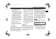
U5P5E0E0.book Page 28 Tuesday, March 21, 2006 12:00 PM PERIODIC MAINTENANCE AND MINOR REPAIR EAU23657 Replacing the fuses The main fuse, the fuse boxes and the ABS motor fuse are located under panel A. (See page 6-5.) 1. 2. 3. 4. 5. 1. 2. 3. 4. Main fuse Fuse box ABS motor fuse ABS motor spare fuse Fuse box Right radiator fan fuse Left radiator fan fuse Hazard fuse Backup fuse (for odometer, clock and immobilizer system) 6. Headlight fuse 7. Signaling system fuse 8. ABS control unit fuse 9.
U5P5E0E0.book Page 29 Tuesday, March 21, 2006 12:00 PM PERIODIC MAINTENANCE AND MINOR REPAIR 3. Turn the key to “ON” and turn on the electrical circuit in question to check if the device operates. 4. If the fuse immediately blows again, have a Yamaha dealer check the electrical system. EAU40360 EAU39880 Headlight bulb Front turn signal light If a headlight does not come on, have a Yamaha dealer check its electrical circuit or replace the bulb.
U5P5E0E0.book Page 30 Tuesday, March 21, 2006 12:00 PM PERIODIC MAINTENANCE AND MINOR REPAIR EAU40990 Replacing a rear turn signal light bulb or a tail/brake light bulb 1. Remove the socket (together with the defective bulb) by turning it counterclockwise. EAU24310 Replacing the license plate light bulb 1. Remove the license plate light unit by removing the screws. 1. Screw 2. License plate light unit 1. Turn signal light bulb socket 2. Tail/brake light bulb socket 2.
U5P5E0E0.book Page 31 Tuesday, March 21, 2006 12:00 PM PERIODIC MAINTENANCE AND MINOR REPAIR EAU39020 6 EAU25870 Auxiliary light bulb Troubleshooting If the auxiliary light does not come on, have a Yamaha dealer check the electrical circuit or replace the bulb. Although Yamaha motorcycles receive a thorough inspection before shipment from the factory, trouble may occur during operation. Any problem in the fuel, compression, or ignition systems, for example, can cause poor starting and loss of power.
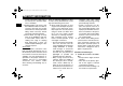
U5P5E0E0.book Page 32 Tuesday, March 21, 2006 12:00 PM PERIODIC MAINTENANCE AND MINOR REPAIR EAU25911 Troubleshooting charts Starting problems or poor engine performance EWA10840 WARNING Keep away open flames and do not smoke while checking or working on the fuel system. 1. Fuel There is enough fuel. Check the compression. There is no fuel. Supply fuel. There is compression. Check the ignition. There is no compression. Have a Yamaha dealer check the vehicle.
U5P5E0E0.book Page 33 Tuesday, March 21, 2006 12:00 PM PERIODIC MAINTENANCE AND MINOR REPAIR Engine overheating EWA10400 WARNING ● ● Do not remove the radiator cap when the engine and radiator are hot. Scalding hot fluid and steam may be blown out under pressure, which could cause serious injury. Be sure to wait until the engine has cooled.
U5P5E0E0.book Page 1 Tuesday, March 21, 2006 12:00 PM MOTORCYCLE CARE AND STORAGE ucts onto seals, gaskets and wheel axles. Always rinse the dirt and degreaser off with water. EAU26060 Care While the open design of a motorcycle reveals the attractiveness of the technology, it also makes it more vulnerable. Rust and corrosion can develop even if high-quality components are used. A rusty exhaust pipe may go unnoticed on a car, however, it detracts from the overall appearance of a motorcycle.
U5P5E0E0.book Page 2 Tuesday, March 21, 2006 12:00 PM MOTORCYCLE CARE AND STORAGE After normal use Remove dirt with warm water, a mild detergent, and a soft, clean sponge, and then rinse thoroughly with clean water. Use a toothbrush or bottlebrush for hard-to-reach areas. Stubborn dirt and insects will come off more easily if the area is covered with a wet cloth for a few minutes before cleaning.
U5P5E0E0.book Page 3 Tuesday, March 21, 2006 12:00 PM MOTORCYCLE CARE AND STORAGE ● Avoid using abrasive polishing compounds as they will wear away the paint. NOTE: Consult a Yamaha dealer for advice on what products to use. EAU26241 Storage Short-term Always store your motorcycle in a cool, dry place and, if necessary, protect it against dust with a porous cover.
U5P5E0E0.book Page 4 Tuesday, March 21, 2006 12:00 PM MOTORCYCLE CARE AND STORAGE 7 4. Lubricate all control cables and the pivoting points of all levers and pedals as well as of the sidestand/centerstand. 5. Check and, if necessary, correct the tire air pressure, and then lift the motorcycle so that both of its wheels are off the ground. Alternatively, turn the wheels a little every month in order to prevent the tires from becoming degraded in one spot. 6.
U5P5E0E0.book Page 1 Tuesday, March 21, 2006 12:00 PM SPECIFICATIONS Dimensions: Overall length: 2230 mm (87.8 in) Overall width: 750 mm (29.5 in) Overall height: 1450 mm (57.1 in) Seat height: 800 mm (31.5 in) Wheelbase: 1545 mm (60.8 in) Ground clearance: 130 mm (5.12 in) Minimum turning radius: 3100 mm (122.0 in) Weight: With oil and fuel: 288.0 kg (635 lb) Engine: Engine type: Liquid cooled 4-stroke, DOHC Cylinder arrangement: Forward-inclined parallel 4-cylinder Displacement: 1298.0 cm³ (79.20 cu.
U5P5E0E0.book Page 2 Tuesday, March 21, 2006 12:00 PM SPECIFICATIONS 3rd: 31/23 (1.348) 4th: 28/26 (1.077) 5th: 26/28 (0.929) Chassis: Frame type: Diamond Caster angle: 26.00 ° Trail: 109.0 mm (4.
U5P5E0E0.book Page 3 Tuesday, March 21, 2006 12:00 PM SPECIFICATIONS Voltage, capacity: 12 V, 12.0 Ah Headlight: Bulb type: Halogen bulb Bulb voltage, wattage × quantity: Headlight: 12 V, 60 W/55.0 W × 2 Tail/brake light: 12 V, 5.0 W/21.0 W × 2 Front turn signal light: 12 V, 21.0 W × 2 Rear turn signal light: 12 V, 21.0 W × 2 Auxiliary light: 12 V, 5.0 W × 2 License plate light: 12 V, 5.
U5P5E0E0.book Page 1 Tuesday, March 21, 2006 12:00 PM CONSUMER INFORMATION EAU26351 Identification numbers EAU26381 EAU26400 Key identification number Vehicle identification number 1. Key identification number 2. Code re-registering key (red bow) 3. Standard keys (black bow) 1.
U5P5E0E0.book Page 2 Tuesday, March 21, 2006 12:00 PM CONSUMER INFORMATION EAU26460 Model label 1. Model label The model label is affixed to the location shown. Record the information on this label in the space provided. This information will be needed when ordering spare parts from a Yamaha dealer.
U5P5E0E0.book Page 1 Tuesday, March 21, 2006 12:00 PM INDEX A ABS....................................................... 3-16 ABS warning light.................................... 3-4 Accessory box....................................... 3-23 Air filter element, cleaning..................... 6-13 Anti-theft alarm (optional)...................... 3-13 Auxiliary DC jack................................... 3-32 Auxiliary light bulb ................................. 6-31 Engine stop switch......................
U5P5E0E0.book Page 2 Tuesday, March 21, 2006 12:00 PM INDEX Storage ................................................... 7-3 Storage compartment ........................... 3-22 Swingarm pivots, lubricating................. 6-24 T Tachometer ............................................ 3-5 Throttle cable free play, checking......... 6-15 Throttle grip and cable, checking and lubricating..................... 6-22 Tires...................................................... 6-16 Tool kit .....................
A5-yoko_Blank.
A5-yoko_Blank.
YAMAHA MOTOR CO., LTD. PRINTED ON RECYCLED PAPER PRINTED IN JAPAN 2006.06-0.