Read this manual carefully before operating this vehicle.
U2D213E0.book Page 1 Friday, September 26, 2008 3:12 PM EAU10042 Read this manual carefully before operating this vehicle. This manual should stay with this vehicle if it is sold.
U2D213E0.book Page 1 Friday, September 26, 2008 3:12 PM INTRODUCTION EAU10081 Congratulations on your purchase of the Yamaha FJR13AEY(C). This model is the result of Yamaha’s vast experience in the production of fine sporting, touring, and pacesetting racing machines. It represents the high degree of craftsmanship and reliability that have made Yamaha a leader in these fields. This manual will give you an understanding of the operation, inspection, and basic maintenance of this motorcycle.
U2D213E0.book Page 1 Friday, September 26, 2008 3:12 PM IMPORTANT MANUAL INFORMATION EAU10132 Particularly important information is distinguished in this manual by the following notations: This is the safety alert symbol. It is used to alert you to potential personal injury hazards. Obey all safety messages that follow this symbol to avoid possible injury or death. WARNING NOTICE TIP A WARNING indicates a hazardous situation which, if not avoided, could result in death or serious injury.
U2D213E0.book Page 2 Friday, September 26, 2008 3:12 PM IMPORTANT MANUAL INFORMATION EAU10193 FJR13AEY(C) OWNER’S MANUAL ©2008 by Yamaha Motor Corporation, U.S.A. 1st edition, September 2008 All rights reserved. Any reprinting or unauthorized use without the written permission of Yamaha Motor Corporation, U.S.A. is expressly prohibited. Printed in Japan.
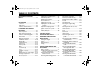
U2D213E0.book Page 1 Friday, September 26, 2008 3:12 PM TABLE OF CONTENTS LOCATION OF IMPORTANT LABELS .............................................1-1 SAFETY INFORMATION ..................2-1 DESCRIPTION ..................................3-1 Left view ..........................................3-1 Right view ........................................3-2 Controls and instruments.................3-3 INSTRUMENT AND CONTROL FUNCTIONS .......................................4-1 YCC-S system .......................
U2D213E0.book Page 2 Friday, September 26, 2008 3:12 PM TABLE OF CONTENTS Lubricating the swingarm pivots ...7-27 Lubricating the rear suspension ...7-28 Checking the front fork .................7-28 Checking the steering ...................7-29 Checking the wheel bearings .......7-29 Battery ..........................................7-29 Replacing the fuses ......................7-31 Headlight bulb ..............................7-32 Front turn signal light ....................
U2D213E0.book Page 1 Friday, September 26, 2008 3:12 PM LOCATION OF IMPORTANT LABELS EAU10383 1 Read and understand all of the labels on your vehicle. They contain important information for safe and proper operation of your vehicle. Never remove any labels from your vehicle. If a label becomes difficult to read or comes off, a replacement label is available from your Yamaha dealer.
U2D213E0.book Page 2 Friday, September 26, 2008 3:12 PM LOCATION OF IMPORTANT LABELS 3 California only 1 California only PRESS.
U2D213E0.book Page 3 Friday, September 26, 2008 3:12 PM LOCATION OF IMPORTANT LABELS 1 5 8 6 9 7 NOTICE Cleaning with alkaline or acid cleaner, gasoline or solvent will damage windshield. Use neutral detergent. 270 kPa, {2.70 kgf/cm 2 }, 39psi 290 kPa, {2.90 kgf/cm 2 }, 42psi 270 kPa, {2.70 kgf/cm 2 }, 39psi 290 kPa, {2.
U2D213E0.book Page 1 Friday, September 26, 2008 3:12 PM SAFETY INFORMATION EAU10283 Be a Responsible Owner As the vehicle’s owner, you are responsible for the safe and proper operation of your motorcycle. Motorcycles are single-track vehicles. Their safe use and operation are dependent upon the use of proper riding techniques as well as the expertise of the operator. Every operator should know the following requirements before riding this motorcycle.
U2D213E0.book Page 2 Friday, September 26, 2008 3:12 PM SAFETY INFORMATION 2 ● ● due to excessive speed or undercornering (insufficient lean angle for the speed). • Always obey the speed limit and never travel faster than warranted by road and traffic conditions. • Always signal before turning or changing lanes. Make sure that other motorists can see you. The posture of the operator and passenger is important for proper control.
U2D213E0.book Page 3 Friday, September 26, 2008 3:12 PM SAFETY INFORMATION ● ● Do not run engine in poorly ventilated or partially enclosed areas such as barns, garages, or carports. Do not run engine outdoors where engine exhaust can be drawn into a building through openings such as windows and doors. Loading Adding accessories or cargo to your motorcycle can adversely affect stability and handling if the weight distribution of the motorcycle is changed.
U2D213E0.book Page 4 Friday, September 26, 2008 3:12 PM SAFETY INFORMATION modifications not specifically recommended by Yamaha, even if sold and installed by a Yamaha dealer. 2 Aftermarket Parts, Accessories, and Modifications While you may find aftermarket products similar in design and quality to genuine Yamaha accessories, recognize that some aftermarket accessories or modifications are not suitable because of potential safety hazards to you or others.
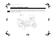
U2D213E0.book Page 1 Friday, September 26, 2008 3:12 PM DESCRIPTION EAU10410 Left view 3 1. 2. 3. 4. 5. 6. 7. 8. 9. YCC-S clutch fluid reservoir (page 7-23) 10.Shock absorber assembly spring preload adjusting lever (page 4-25) 11.Air filter element (page 7-18) 12.Shift pedal (page 4-12) 13.Engine oil filler cap (page 7-12) 14.Engine oil filter cartridge (page 7-12) 15.
U2D213E0.book Page 2 Friday, September 26, 2008 3:12 PM DESCRIPTION EAU10420 Right view 3 1. 2. 3. 4. 5. 6. 7. 8. 9. Shock absorber assembly rebound damping force adjusting knob (page 4-25) 10.
U2D213E0.book Page 3 Friday, September 26, 2008 3:12 PM DESCRIPTION EAU10430 Controls and instruments 3 1. 2. 3. 4. 5. 6. 7. 8. 9. Throttle grip (page 7-19) 10.Main switch/steering lock (page 4-1) 11.Headlight beam adjusting knob (page 4-22) 12.Grip warmer adjusting knob (page 4-27) 13.
U2D213E0.book Page 1 Friday, September 26, 2008 3:12 PM INSTRUMENT AND CONTROL FUNCTIONS EAU40472 YCC-S system 4 This vehicle features the YCC-S (Yamaha Chip Controlled-Shift) system. The basic function of this system allows the rider to shift gears without the use of a clutch lever. Furthermore, a shift lever is equipped on the handlebar, allowing the rider to choose to shift gears either with the shift pedal or by hand.
U2D213E0.book Page 2 Friday, September 26, 2008 3:12 PM INSTRUMENT AND CONTROL FUNCTIONS EAU10661 OFF All electrical systems are off. The key can be removed. To lock the steering To unlock the steering 1. Push. 2. Turn. 1. Push. 2. Turn. EWA10061 WARNING Never turn the key to “OFF” or “LOCK” while the vehicle is moving. Otherwise the electrical systems will be switched off, which may result in loss of control or an accident. EAU10691 LOCK The steering is locked, and all electrical systems are off.
U2D213E0.book Page 3 Friday, September 26, 2008 3:12 PM INSTRUMENT AND CONTROL FUNCTIONS EAU11003 Indicator and warning lights EAU11060 Neutral indicator light “ ” This indicator light comes on when the transmission is in the neutral position. EAU11080 High beam indicator light “ ” This indicator light comes on when the high beam of the headlight is switched on. 4 EAU40516 Engine trouble “ ”/YCC-S “SHIFT” indicators and warning light Engine trouble warning light indicator “ ” and EAU11121 1.
U2D213E0.book Page 4 Friday, September 26, 2008 3:12 PM INSTRUMENT AND CONTROL FUNCTIONS YCC-S indicator “SHIFT” and warning light TIP In order to be able to move the vehicle after it has stopped, if shifting is impossible using the hand shift lever and shift pedal, proceed as follows: Place the vehicle on the centerstand, then while rotating the rear wheel, push the shift pedal rod and pivot forward until the transmission is in the neutral position.
U2D213E0.book Page 5 Friday, September 26, 2008 3:12 PM INSTRUMENT AND CONTROL FUNCTIONS EAU11601 EAU11872 EAU40855 Speedometer Tachometer Multi-function display 1. Tachometer 2. Speedometer 3. Multi-function display 1. Tachometer 2. Tachometer red zone 1. Multi-function display 2. Select button 3. Reset button 4 The speedometer shows the riding speed.
U2D213E0.book Page 6 Friday, September 26, 2008 3:12 PM INSTRUMENT AND CONTROL FUNCTIONS ● ● ● ● ● ● ● ● a fuel reserve tripmeter (which shows the distance traveled on the fuel reserve) a clock a fuel meter a coolant temperature meter a transmission gear display an ambient temperature display a fuel consumption display (instantaneous and average consumption functions) a self-diagnosis device TIP Be sure to turn the key to “ON” before using the select and reset buttons.
U2D213E0.book Page 7 Friday, September 26, 2008 3:12 PM INSTRUMENT AND CONTROL FUNCTIONS Clock Fuel meter play segments will start flashing. If this occurs, have a Yamaha dealer check the electrical circuit. Coolant temperature meter 4 1. Clock 2. Select button 3. Reset button To set the clock: 1. Push the select button and reset button together for at least two seconds. 2. When the hour digits start flashing, push the reset button to set the hours. 3.
U2D213E0.book Page 8 Friday, September 26, 2008 3:12 PM INSTRUMENT AND CONTROL FUNCTIONS ECA10021 NOTICE Do not continue to operate the engine if it is overheating. Ambient temperature, instantaneous fuel consumption and average fuel consumption modes Ambient temperature mode Transmission gear display 1. Ambient temperature 1. Ambient temperature/instantaneous fuel consumption/average fuel consumption 2. Select button 3. Reset button 1. Transmission gear display 2.
U2D213E0.book Page 9 Friday, September 26, 2008 3:12 PM INSTRUMENT AND CONTROL FUNCTIONS 20 km/h (12.5 mi/h)] or when stopped at traffic signals, railroad crossings, etc. Average fuel consumption mode Instantaneous fuel consumption mode ● After resetting the average fuel consumption display, “_ _._” will be shown for that display until the vehicle has traveled 1 km (0.6 mi). ECA15472 NOTICE If there is a malfunction, “– –.–” will be displayed. Have a Yamaha dealer check the vehicle. 4 1.
U2D213E0.book Page 10 Friday, September 26, 2008 3:12 PM INSTRUMENT AND CONTROL FUNCTIONS If the multi-function display indicates such an error code, note the code number, and then have a Yamaha dealer check the vehicle. EAU12347 Handlebar switches Right Left ECA11790 NOTICE If the multi-function display indicates an error code, the vehicle should be checked as soon as possible in order to avoid engine damage. 1. 2. 3. 4. 5.
U2D213E0.book Page 11 Friday, September 26, 2008 3:12 PM INSTRUMENT AND CONTROL FUNCTIONS EAU12493 EAU12660 Windshield position adjusting switch “ ” To move the windshield up, push this switch in direction (a). To move the windshield down, push the switch in direction (b). Engine stop switch “ / ” Set this switch to “ ” before starting the engine. Set this switch to “ ” to stop the engine in case of an emergency, such as when the vehicle overturns or when the throttle cable is stuck.
U2D213E0.book Page 12 Friday, September 26, 2008 3:12 PM INSTRUMENT AND CONTROL FUNCTIONS The hand shift control switch enables shifting gears with the hand shift lever. When the switch is set to enable hand shifting, the hand shift control indicator light will come on. EAU40493 Shift pedal TIP ● ● The shift pedal can be used to shift gears whether the hand shift lever is enabled or not. When the main switch is turned to “OFF”, the hand shifting mode will automatically be disabled.
U2D213E0.book Page 13 Friday, September 26, 2008 3:12 PM INSTRUMENT AND CONTROL FUNCTIONS EAU40481 Hand shift lever “ ”/“ ” EAU26823 Brake lever EAU39540 Brake pedal The brake lever is located at the right handlebar grip. To apply the front brake, pull the lever toward the handlebar grip. 4 1. Hand shift lever “ ” 2. Hand shift lever “ ” 3. Hand shift control switch The hand shift lever must be enabled by pressing the hand shift control switch prior to shifting gears.
U2D213E0.book Page 14 Friday, September 26, 2008 3:12 PM INSTRUMENT AND CONTROL FUNCTIONS EAU39531 ABS The Yamaha ABS (Anti-lock Brake System) features a dual electronic control system, which acts on the front and rear brakes independently. The ABS is monitored by an ECU (Electronic Control Unit), which will have recourse to manual braking if a malfunction occurs. ● EWA10090 WARNING ● ● The ABS performs best on long braking distances.
U2D213E0.book Page 15 Friday, September 26, 2008 3:12 PM INSTRUMENT AND CONTROL FUNCTIONS EAU13074 Fuel tank cap EAU13221 TIP The fuel tank cap cannot be closed unless the key is in the lock. In addition, the key cannot be removed if the cap is not properly closed and locked. EWA11091 WARNING Make sure that the fuel tank cap is properly closed after filling fuel. Leaking fuel is a fire hazard. 4 1. Fuel tank cap lock cover 2. Unlock. Fuel Make sure there is sufficient gasoline in the tank.
U2D213E0.book Page 16 Friday, September 26, 2008 3:12 PM INSTRUMENT AND CONTROL FUNCTIONS ately. If gasoline spills on your skin, wash with soap and water. If gasoline spills on your clothing, change your clothes. EAU13301 1. Fuel tank filler tube 2. Fuel level 3. Wipe up any spilled fuel immediately. NOTICE: Immediately wipe off spilled fuel with a clean, dry, soft cloth, since fuel may deteriorate painted surfaces or plastic parts. [ECA10071] 4. Be sure to securely close the fuel tank cap.
U2D213E0.book Page 17 Friday, September 26, 2008 3:12 PM INSTRUMENT AND CONTROL FUNCTIONS EAU13445 NOTICE This vehicle is equipped with catalytic converters in the exhaust system. Use only unleaded gasoline. The use of leaded gasoline will cause unrepairable damage to the catalytic converter. EWA10862 WARNING 4 ECA10701 Catalytic converters The exhaust system is hot after operation.
U2D213E0.book Page 18 Friday, September 26, 2008 3:12 PM INSTRUMENT AND CONTROL FUNCTIONS 2. Install the passenger seat. To install the passenger seat 1. Insert the projections on the rear of the passenger seat into the seat holders as shown, and then push the front of the seat down to lock it in place. TIP ● ● 1. Rider seat lock lever 2. Rider seat 1. Projection 2. Seat holder To install the rider seat 1.
U2D213E0.book Page 19 Friday, September 26, 2008 3:12 PM INSTRUMENT AND CONTROL FUNCTIONS EAU39632 Adjusting the rider seat height The rider seat height can be adjusted to one of two positions to suit the rider’s preference. The rider seat height was adjusted to the lower position at delivery. 1. Rider seat height position adjuster 4 3. Move the rider seat holder cover to the lower position as shown. 1. Rider seat height position adjuster 2. “H” mark 3. Match mark 5.
U2D213E0.book Page 20 Friday, September 26, 2008 3:12 PM INSTRUMENT AND CONTROL FUNCTIONS 6. Align the projection on the bottom of the rider seat with the “L” position slot, and then push the rear of the seat down to lock it in place as shown. 6. Align the projection on the bottom of the rider seat with the “H” position slot, and then push the rear of the seat down to lock it in place as shown. 1. Rider seat height position adjuster 2. “L” mark 3. Match mark 1. “H” position slot 5.
U2D213E0.book Page 21 Friday, September 26, 2008 3:12 PM INSTRUMENT AND CONTROL FUNCTIONS EAU14461 Storage compartment EAU39480 Accessory box The accessory box is located beside the meter panel. To open the accessory box 1. Insert the key into the main switch, and then turn it to “ON”. 2. Push the accessory box button, and then open the accessory box lid. 4 2. Remove the key. ECA11800 NOTICE Do not place heat-sensitive items in the accessory box.
U2D213E0.book Page 22 Friday, September 26, 2008 3:12 PM INSTRUMENT AND CONTROL FUNCTIONS EAU39611 Adjusting the headlight beams The headlight beam adjusting knobs are used to raise or lower the height of the headlight beams. It may be necessary to adjust the headlight beams to increase visibility and help prevent blinding oncoming drivers when carrying more or less load than usual. Obey local laws and regulations when adjusting the headlights.
U2D213E0.book Page 23 Friday, September 26, 2008 3:12 PM INSTRUMENT AND CONTROL FUNCTIONS EAU39671 Rear view mirrors The rear view mirrors of this vehicle can be folded forward or backward for parking in narrow spaces. Fold the mirrors back to their original position before riding. 4 1. Quick fastener screw 1. Quick fastener screw 2. Pull the cowling to the open position, and then install the quick fastener screws. 2.
U2D213E0.book Page 24 Friday, September 26, 2008 3:12 PM INSTRUMENT AND CONTROL FUNCTIONS EAU14732 Adjusting the front fork EWA10180 WARNING Always adjust both fork legs equally, otherwise poor handling and loss of stability may result. This front fork is equipped with spring preload adjusting bolts, rebound damping force adjusting knobs and compression damping force adjusting screws.
U2D213E0.book Page 25 Friday, September 26, 2008 3:12 PM INSTRUMENT AND CONTROL FUNCTIONS Compression damping force 4 1. Compression damping force adjusting screw To increase the compression damping force and thereby harden the compression damping, turn the adjusting screw on each fork leg in direction (a). To decrease the compression damping force and thereby soften the compression damping, turn the adjusting screw on each fork leg in direction (b).
U2D213E0.book Page 26 Friday, September 26, 2008 3:12 PM INSTRUMENT AND CONTROL FUNCTIONS For riding solo, move the spring preload adjusting lever in direction (b). For riding with a passenger, move the spring preload adjusting lever in direction (a). Rebound damping force 1. Rebound damping force adjusting knob To increase the rebound damping force and thereby harden the rebound damping, turn the adjusting knob in direction (a).
U2D213E0.book Page 27 Friday, September 26, 2008 3:12 PM INSTRUMENT AND CONTROL FUNCTIONS EAU40502 EAU15301 Grip warmer adjusting knob Sidestand The sidestand is located on the left side of the frame. Raise the sidestand or lower it with your foot while holding the vehicle upright. EWA14510 WARNING Do not turn the grip warmer knob while the vehicle is moving. ECA15520 NOTICE ● 4 ● ● Be sure to wear gloves when using the grip warmers.
U2D213E0.book Page 28 Friday, September 26, 2008 3:12 PM INSTRUMENT AND CONTROL FUNCTIONS below and have a Yamaha dealer repair it if it does not function properly. EAU40524 Ignition circuit cut-off system The ignition circuit cut-off system (comprising the sidestand switch and brake light switches) has the following functions. ● It prevents starting when the sidestand is up, but neither brake is applied. ● It prevents starting when either brake is applied, but the sidestand is still down.
U2D213E0.book Page 29 Friday, September 26, 2008 3:12 PM INSTRUMENT AND CONTROL FUNCTIONS With the engine turned off: 1. Move the sidestand down. 2. Make sure that the engine stop switch is set to “ 3. Turn the key on. 4. Shift the transmission into the neutral position. 5. Keep the front or rear brake applied. 6. Push the start switch. Does the engine start? 4 YES WARNING • The vehicle must be placed on the center- ”. stand during this inspection.
U2D213E0.book Page 30 Friday, September 26, 2008 3:12 PM INSTRUMENT AND CONTROL FUNCTIONS EAU39652 Auxiliary DC jack ECA15430 NOTICE The accessory connected to the auxiliary DC jack should not be used with the engine turned off, and the load must never exceed 30 W (2.5 A), otherwise the battery may discharge. 1. Auxiliary DC jack cap EWA14360 WARNING To prevent electrical shock or shortcircuiting, make sure that the cap is installed when the auxiliary DC jack is not being used.
U2D213E0.book Page 1 Friday, September 26, 2008 3:12 PM FOR YOUR SAFETY – PRE-OPERATION CHECKS EAU15596 Inspect your vehicle each time you use it to make sure the vehicle is in safe operating condition. Always follow the inspection and maintenance procedures and schedules described in the Owner’s Manual. EWA11151 WARNING Failure to inspect or maintain the vehicle properly increases the possibility of an accident or equipment damage. Do not operate the vehicle if you find any problem.
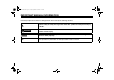
U2D213E0.book Page 2 Friday, September 26, 2008 3:12 PM FOR YOUR SAFETY – PRE-OPERATION CHECKS ITEM CHECKS PAGE Rear brake • • • • • • • Check operation. If soft or spongy, have Yamaha dealer bleed hydraulic system. Check brake pads for wear. Replace if necessary. Check fluid level in reservoir. If necessary, add recommended brake fluid to specified level. Check hydraulic system for leakage. 7-23, 7-23 YCC-S clutch • • • • Check operation. Check fluid level in reservoir.
U2D213E0.book Page 3 Friday, September 26, 2008 3:12 PM FOR YOUR SAFETY – PRE-OPERATION CHECKS ITEM Sidestand switch CHECKS • Check operation of ignition circuit cut-off system. • If system is not working correctly, have Yamaha dealer check vehicle.
U2D213E0.book Page 1 Friday, September 26, 2008 3:12 PM OPERATION AND IMPORTANT RIDING POINTS EAU15951 EAU46632 EAU40845 Starting the engine Read the Owner’s Manual carefully to become familiar with all controls. If there is a control or function you do not understand, ask your Yamaha dealer. EWA10271 WARNING Failure to familiarize yourself with the controls can lead to loss of control, which could cause an accident or injury.
U2D213E0.book Page 2 Friday, September 26, 2008 3:12 PM OPERATION AND IMPORTANT RIDING POINTS ● ● Engine trouble/YCC-S indicators and warning light ABS warning light EAU40572 Shifting ECA16311 NOTICE If a warning light or indicator does not go off, see page 4-3 for the corresponding circuit check. 6 2. Shift the transmission into the neutral position (see page 6-2) with the front or rear brake applied. The neutral indicator light should come on.
U2D213E0.book Page 3 Friday, September 26, 2008 3:12 PM OPERATION AND IMPORTANT RIDING POINTS ● Always return the throttle to the closed position while changing gears to avoid damaging the engine, transmission, and drive train, which are not designed to withstand the shock of forced shifting. TIP ● ● ● When shifting from neutral to first gear, the engine speed must be lower than approximately 1300 r/min and the sidestand must be up. Shifting up is impossible if the engine speed is too low.
U2D213E0.book Page 4 Friday, September 26, 2008 3:12 PM OPERATION AND IMPORTANT RIDING POINTS EAU16841 Engine break-in 6 There is never a more important period in the life of your engine than the period between 0 and 1600 km (1000 mi). For this reason, you should read the following material carefully. Since the engine is brand new, do not put an excessive load on it for the first 1600 km (1000 mi). The various parts in the engine wear and polish themselves to the correct operating clearances.
U2D213E0.book Page 5 Friday, September 26, 2008 3:12 PM OPERATION AND IMPORTANT RIDING POINTS ● ● Do not park on a slope or on soft ground, otherwise the vehicle may overturn, increasing the risk of a fuel leak and fire. Do not park near grass or other flammable materials which might catch fire.
U2D213E0.book Page 1 Friday, September 26, 2008 3:12 PM PERIODIC MAINTENANCE AND ADJUSTMENT EAU17232 Periodic inspection, adjustment, and lubrication will keep your vehicle in the safest and most efficient condition possible. Safety is an obligation of the vehicle owner/operator. The most important points of vehicle inspection, adjustment, and lubrication are explained on the following pages.
U2D213E0.book Page 2 Friday, September 26, 2008 3:12 PM PERIODIC MAINTENANCE AND ADJUSTMENT EAU17361 Owner’s tool kit 1. Owner’s tool kit The owner’s tool kit is located under the rider seat. (See page 4-17.) The service information included in this manual and the tools provided in the owner’s tool kit are intended to assist you in the performance of preventive maintenance and minor repairs. However, additional tools such as a torque wrench may be necessary to perform certain maintenance work correctly.
U2D213E0.book Page 3 Friday, September 26, 2008 3:12 PM PERIODIC MAINTENANCE AND ADJUSTMENT EAU17600 Periodic maintenance chart for the emission control system INITIAL No. ITEM ROUTINE 600 mi (1000 km) or 1 month ODOMETER READINGS 4000 mi (7000 km) or 6 months 8000 mi 12000 mi 16000 mi 20000 mi (13000 km) (19000 km) (25000 km) (31000 km) or or or or 12 months 18 months 24 months 30 months Fuel line • Check fuel hoses for cracks or damage. • Replace if necessary.
U2D213E0.book Page 4 Friday, September 26, 2008 3:12 PM PERIODIC MAINTENANCE AND ADJUSTMENT EAU32185 General maintenance and lubrication chart INITIAL No. ITEM ROUTINE 600 mi (1000 km) or 1 month ODOMETER READINGS 4000 mi (7000 km) or 6 months 8000 mi 12000 mi 16000 mi 20000 mi (13000 km) (19000 km) (25000 km) (31000 km) or or or or 12 months 18 months 24 months 30 months 1 * Air filter element • Clean with compressed air. • Replace if necessary.
U2D213E0.book Page 5 Friday, September 26, 2008 3:12 PM PERIODIC MAINTENANCE AND ADJUSTMENT INITIAL No. ROUTINE Swingarm pivot bearings • Check bearing assemblies for looseness. • Moderately repack with lithiumsoap-based grease. 10 * Steering bearings • Check bearing assemblies for looseness. • Moderately repack with lithiumsoap-based grease every 16000 mi (25000 km) or 24 months.
U2D213E0.book Page 6 Friday, September 26, 2008 3:12 PM PERIODIC MAINTENANCE AND ADJUSTMENT INITIAL ITEM 18 * Shock absorber assembly • Check operation and for oil leakage. • Replace if necessary. 19 * Rear suspension link pivots • Apply lithium-soap-based grease lightly. 20 Engine oil • Change (warm engine before draining). √ 21 * Engine oil filter cartridge • Replace. √ 22 * Cooling system ROUTINE 600 mi (1000 km) or 1 month No.
U2D213E0.book Page 7 Friday, September 26, 2008 3:12 PM PERIODIC MAINTENANCE AND ADJUSTMENT INITIAL No. ITEM ROUTINE 26 * Throttle grip housing and cable • Check operation and free play. • Adjust the throttle cable free play if necessary. • Lubricate the throttle grip housing and cable. 27 * Lights, signals and switches • Check operation. • Adjust headlight beam.
U2D213E0.book Page 8 Friday, September 26, 2008 3:12 PM PERIODIC MAINTENANCE AND ADJUSTMENT EAU18771 Removing and installing panels The panels shown need to be removed to perform some of the maintenance jobs described in this chapter. Refer to this section each time a panel needs to be removed and installed. 1. Panel B 1. Panel A 2. Bolt 3. Quick fastener To install the panel Place the panel in the original position, and then install the bolts and the quick fastener. 7 1.
U2D213E0.book Page 9 Friday, September 26, 2008 3:12 PM PERIODIC MAINTENANCE AND ADJUSTMENT 3. Pull the bottom of the panel outward, pull the front of the panel downward, and then slide the panel forward to release it in the rear as shown. 1 1 1. Panel B 2. Bolt 3. Quick fastener screw 1. Panel B 1 1. Panel B 1 7 1. Panel C 1. Panel C 2. Bolt 3. Quick fastener screw 1.
U2D213E0.book Page 10 Friday, September 26, 2008 3:12 PM PERIODIC MAINTENANCE AND ADJUSTMENT 1 1. Panel C 1. Panel B 2. Rear cowling 1 1 2 1 1. Panel B 2 2 1 1 7 1. Panel C To install the panel 1. Insert the rear of the panel into the rear cowling as shown, and then insert the top edge of the panel into the fuel tank side cover. 1. Panel B 2. Fuel tank side cover 2. Push the bottom of the panel in as shown. 7-10 1. Panel C 2.
U2D213E0.book Page 11 Friday, September 26, 2008 3:12 PM PERIODIC MAINTENANCE AND ADJUSTMENT EAU19642 2 1 1. Panel C 2. Fuel tank side cover 1 7 1. Panel C 3. Install the bolts and the quick fastener screws. 4. Install the seats. Checking the spark plugs The spark plugs are important engine components, which should be checked periodically, preferably by a Yamaha dealer.
U2D213E0.book Page 12 Friday, September 26, 2008 3:12 PM PERIODIC MAINTENANCE AND ADJUSTMENT EAU19681 Tightening torque: Spark plug: 12.5 Nm (1.25 m·kgf, 9.0 ft·lbf) Canister (for California only) EAU19885 Engine oil and oil filter cartridge The engine oil level should be checked before each ride. In addition, the oil must be changed and the oil filter cartridge replaced at the intervals specified in the periodic maintenance and lubrication chart.
U2D213E0.book Page 13 Friday, September 26, 2008 3:12 PM PERIODIC MAINTENANCE AND ADJUSTMENT 4. Remove the engine oil filler cap and drain bolt to drain the oil from the crankcase. 1. Engine oil level check window 2. Maximum level mark 3. Minimum level mark 4. If the engine oil is below the minimum level mark, add sufficient oil of the recommended type to raise it to the correct level. 7 To change the engine oil (with or without oil filter cartridge replacement) 1. Place the vehicle on a level surface.
U2D213E0.book Page 14 Friday, September 26, 2008 3:12 PM PERIODIC MAINTENANCE AND ADJUSTMENT Tightening torque: Oil filter cartridge: 17 Nm (1.7 m·kgf, 12 ft·lbf) 8. Install the engine oil drain bolt, and then tighten it to the specified torque. 1. O-ring TIP Make sure that the O-ring is properly seated. 7. Install the new oil filter cartridge, and then tighten it to the specified torque with a torque wrench. TIP Check the washer for damage and replace it if necessary.
U2D213E0.book Page 15 Friday, September 26, 2008 3:12 PM PERIODIC MAINTENANCE AND ADJUSTMENT 1 11. Turn the engine off, and then check the oil level and correct it if necessary. 2 1. “CD” specification 2. “ENERGY CONSERVING II” The final gear case must be checked for oil leakage before each ride. If any leakage is found, have a Yamaha dealer check and repair the vehicle.
U2D213E0.book Page 16 Friday, September 26, 2008 3:12 PM PERIODIC MAINTENANCE AND ADJUSTMENT 2. Remove the final gear oil filler bolt, and then check the oil level in the final gear case. TIP The oil level should be at the brim of the filler hole. 1. Final gear oil filler bolt 2. Final gear oil drain bolt 3. Correct oil level 3. If the oil is below the brim of the filler hole, add sufficient oil of the recommended type to raise it to the correct level. 4.
U2D213E0.book Page 17 Friday, September 26, 2008 3:12 PM PERIODIC MAINTENANCE AND ADJUSTMENT EAU20070 Coolant The coolant level should be checked before each ride. In addition, the coolant must be changed at the intervals specified in the periodic maintenance and lubrication chart. EAU40153 To check the coolant level 1. Place the vehicle on the centerstand. TIP ● ● 7 The coolant level must be checked on a cold engine since the level varies with engine temperature.
U2D213E0.book Page 18 Friday, September 26, 2008 3:12 PM PERIODIC MAINTENANCE AND ADJUSTMENT EAU33031 Changing the coolant The coolant must be changed at the intervals specified in the periodic maintenance and lubrication chart. Have a Yamaha dealer change the coolant. WARNING! Never attempt to remove the radiator cap when the engine is hot.
U2D213E0.book Page 19 Friday, September 26, 2008 3:12 PM PERIODIC MAINTENANCE AND ADJUSTMENT EAU21382 Checking the throttle cable free play EAU21401 EAU21751 Valve clearance Tires The valve clearance changes with use, resulting in improper air-fuel mixture and/or engine noise. To prevent this from occurring, the valve clearance must be adjusted by a Yamaha dealer at the intervals specified in the periodic maintenance and lubrication chart.
U2D213E0.book Page 20 Friday, September 26, 2008 3:12 PM PERIODIC MAINTENANCE AND ADJUSTMENT Tire air pressure (measured on cold tires): 0–90 kg (0–198 lb): Front: 270 kPa (2.70 kgf/cm², 39 psi) Rear: 290 kPa (2.90 kgf/cm², 42 psi) FJR13AEY 90–208 kg (198–459 lb) FJR13AEYC 90–207 kg (198–456 lb): Front: 270 kPa (2.70 kgf/cm², 39 psi) Rear: 290 kPa (2.90 kgf/cm², 42 psi) High-speed riding: Front: 270 kPa (2.70 kgf/cm², 39 psi) Rear: 290 kPa (2.
U2D213E0.book Page 21 Friday, September 26, 2008 3:12 PM PERIODIC MAINTENANCE AND ADJUSTMENT This motorcycle is equipped with cast wheels and tubeless tires with valves. EWA10481 WARNING ● ● ● 7 The front and rear tires should be of the same make and design, otherwise the handling characteristics of the motorcycle may be different, which could lead to an accident. Always make sure that the valve caps are securely installed to prevent air pressure leakage.
U2D213E0.book Page 22 Friday, September 26, 2008 3:12 PM PERIODIC MAINTENANCE AND ADJUSTMENT EAU21960 EAU40620 EAU36502 Cast wheels YCC-S clutch Rear brake light switch To maximize the performance, durability, and safe operation of your vehicle, note the following points regarding the specified wheels. ● The wheel rims should be checked for cracks, bends or warpage before each ride. If any damage is found, have a Yamaha dealer replace the wheel. Do not attempt even the smallest repair to the wheel.
U2D213E0.book Page 23 Friday, September 26, 2008 3:12 PM PERIODIC MAINTENANCE AND ADJUSTMENT EAU22390 Checking the front and rear brake pads The front and rear brake pads must be checked for wear at the intervals specified in the periodic maintenance and lubrication chart. cator groove has almost disappeared, have a Yamaha dealer replace the brake pads as a set. EAU22500 EAU40591 Checking the brake and YCC-S clutch fluid levels Front brake Rear brake pads EAU43431 Front brake pads 1.
U2D213E0.book Page 24 Friday, September 26, 2008 3:12 PM PERIODIC MAINTENANCE AND ADJUSTMENT YCC-S clutch 1. Minimum level mark Insufficient brake fluid may allow air to enter the brake or YCC-S clutch systems, possibly causing them to become ineffective. Before riding, check that the brake fluid is above the minimum level mark and replenish if necessary. A low brake fluid level may indicate worn brake pads and/or brake system leakage.
U2D213E0.book Page 25 Friday, September 26, 2008 3:12 PM PERIODIC MAINTENANCE AND ADJUSTMENT EAU40601 7 EAU23093 EAU23111 Changing the brake and YCC-S clutch fluids Checking and lubricating the cables Checking and lubricating the throttle grip and cable Have a Yamaha dealer change the brake and YCC-S clutch fluids at the intervals specified in the TIP after the periodic maintenance and lubrication chart.
U2D213E0.book Page 26 Friday, September 26, 2008 3:12 PM PERIODIC MAINTENANCE AND ADJUSTMENT EAU44271 Checking and lubricating the brake and shift pedals EAU23153 Recommended lubricant: Lithium-soap-based grease Checking and lubricating the brake lever The operation of the brake lever should be checked before each ride, and the lever pivots should be lubricated if necessary.
U2D213E0.book Page 27 Friday, September 26, 2008 3:12 PM PERIODIC MAINTENANCE AND ADJUSTMENT EAU23213 Checking and lubricating the centerstand and sidestand 7 EAUM1650 Recommended lubricant: Lithium-soap-based grease The operation of the centerstand and sidestand should be checked before each ride, and the pivots and metal-tometal contact surfaces should be lubricated if necessary.
U2D213E0.book Page 28 Friday, September 26, 2008 3:12 PM PERIODIC MAINTENANCE AND ADJUSTMENT EAU23250 Lubricating the rear suspension EAU23272 Checking the front fork The condition and operation of the front fork must be checked as follows at the intervals specified in the periodic maintenance and lubrication chart. To check the condition Check the inner tubes for scratches, damage and excessive oil leakage.
U2D213E0.book Page 29 Friday, September 26, 2008 3:12 PM PERIODIC MAINTENANCE AND ADJUSTMENT EAU45511 7 EAU23290 Checking the steering Checking the wheel bearings Worn or loose steering bearings may cause danger. Therefore, the operation of the steering must be checked as follows at the intervals specified in the periodic maintenance and lubrication chart. 1. Place the vehicle on the centerstand. WARNING! To avoid injury, securely support the vehicle so there is no danger of it falling over.
U2D213E0.book Page 30 Friday, September 26, 2008 3:12 PM PERIODIC MAINTENANCE AND ADJUSTMENT ● ● skin, eyes or clothing and always shield your eyes when working near batteries. In case of contact, administer the following FIRST AID. • EXTERNAL: Flush with plenty of water. • INTERNAL: Drink large quantities of water or milk and immediately call a physician. • EYES: Flush with water for 15 minutes and seek prompt medical attention. Batteries produce explosive hydrogen gas.
U2D213E0.book Page 31 Friday, September 26, 2008 3:12 PM PERIODIC MAINTENANCE AND ADJUSTMENT EAU23659 Replacing the fuses 7 20 The main fuse, the fuse boxes and the ABS motor fuse are located under panel A. (See page 7-8.) 2 14 0 13 12 11 10 9 8 7 1. 2. 3. 4. Main fuse Fuse box ABS motor fuse ABS motor spare fuse 1. Fuse box 2. Right radiator fan fuse 3. Left radiator fan fuse 4. Hazard fuse 5. Backup fuse (for odometer and clock) 6. ABS solenoid fuse 7. Fuel injection system fuse 8.
U2D213E0.book Page 32 Friday, September 26, 2008 3:12 PM PERIODIC MAINTENANCE AND ADJUSTMENT 3. Turn the key to “ON” and turn on the electrical circuit in question to check if the device operates. 4. If the fuse immediately blows again, have a Yamaha dealer check the electrical system. EAU40361 EAU39880 Headlight bulb Front turn signal light If a headlight does not come on, have a Yamaha dealer check its electrical circuit or replace the bulb.
U2D213E0.book Page 33 Friday, September 26, 2008 3:12 PM PERIODIC MAINTENANCE AND ADJUSTMENT EAU27003 Replacing a rear turn signal light bulb or a tail/brake light bulb 6. Install the passenger seat. EAU24312 Replacing the license plate light bulb 1. Remove the license plate light unit by removing the screws. 1. Remove the passenger seat. (See page 4-17.) 2. Remove the socket (together with the bulb) by turning it counterclockwise. 1. Screw 2. License plate light unit 2.
U2D213E0.book Page 34 Friday, September 26, 2008 3:12 PM PERIODIC MAINTENANCE AND ADJUSTMENT 3. Remove the burnt-out bulb by pulling it out. 4. Insert a new bulb into the socket. 5. Install the socket (together with the bulb) by pushing it in. 6. Install the license plate light unit by installing the screws. EAU25871 Troubleshooting Although Yamaha motorcycles receive a thorough inspection before shipment from the factory, trouble may occur during operation.
U2D213E0.book Page 35 Friday, September 26, 2008 3:12 PM PERIODIC MAINTENANCE AND ADJUSTMENT EAU42501 Troubleshooting charts Starting problems or poor engine performance 1. Fuel There is enough fuel. Check the compression. There is no fuel. Supply fuel. There is compression. Check the ignition. There is no compression. Have a Yamaha dealer check the vehicle. Check the fuel level in the fuel tank. The engine does not start. Check the compression. 2. Compression Operate the electric starter. 3.
U2D213E0.book Page 36 Friday, September 26, 2008 3:12 PM PERIODIC MAINTENANCE AND ADJUSTMENT Engine overheating EWAT1040 WARNING ● ● Do not remove the radiator cap when the engine and radiator are hot. Scalding hot fluid and steam may be blown out under pressure, which could cause serious injury. Be sure to wait until the engine has cooled. Place a thick rag, like a towel, over the radiator cap, and then slowly rotate the cap counterclockwise to the detent to allow any residual pressure to escape.
U2D213E0.book Page 1 Friday, September 26, 2008 3:12 PM MOTORCYCLE CARE AND STORAGE EAU37833 Matte color caution ECA15192 NOTICE Some models are equipped with matte colored finished parts. Be sure to consult a Yamaha dealer for advice on what products to use before cleaning the vehicle. Using a brush, harsh chemical products or cleaning compounds when cleaning these parts will scratch or damage their surface. Wax also should not be applied to any matte colored finished parts.
U2D213E0.book Page 2 Friday, September 26, 2008 3:12 PM MOTORCYCLE CARE AND STORAGE ● ● ● off any detergent residue using plenty of water, as it is harmful to plastic parts. Do not use any harsh chemical products on plastic parts. Be sure to avoid using cloths or sponges which have been in contact with strong or abrasive cleaning products, solvent or thinner, fuel (gasoline), rust removers or inhibitors, brake fluid, antifreeze or electrolyte.
U2D213E0.book Page 3 Friday, September 26, 2008 3:12 PM MOTORCYCLE CARE AND STORAGE 3. To prevent corrosion, it is recommended to apply a corrosion protection spray on all metal, including chrome- and nickel-plated, surfaces. 4. Use spray oil as a universal cleaner to remove any remaining dirt. 5. Touch up minor paint damage caused by stones, etc. 6. Wax all painted surfaces. 7. Let the motorcycle dry completely before storing or covering it.
U2D213E0.book Page 4 Friday, September 26, 2008 3:12 PM MOTORCYCLE CARE AND STORAGE 3. Perform the following steps to protect the cylinders, piston rings, etc. from corrosion. a. Remove the spark plug caps and spark plugs. b. Pour a teaspoonful of engine oil into each spark plug bore. c. Install the spark plug caps onto the spark plugs, and then place the spark plugs on the cylinder head so that the electrodes are grounded. (This will limit sparking during the next step.) d.
U2D213E0.book Page 1 Friday, September 26, 2008 3:12 PM SPECIFICATIONS Dimensions: Overall length: 2230 mm (87.8 in) Overall width: 750 mm (29.5 in) Overall height: 1450 mm (57.1 in) Seat height: 805 mm (31.7 in) Wheelbase: 1545 mm (60.8 in) Ground clearance: 130 mm (5.12 in) Minimum turning radius: 3100 mm (122.0 in) Weight: With oil and fuel: FJR13AEY 295.0 kg (650 lb) FJR13AEYC 296.
U2D213E0.book Page 2 Friday, September 26, 2008 3:12 PM SPECIFICATIONS Transmission type: Constant mesh 5-speed Operation: Left foot and left hand Gear ratio: 1st: 43/17 (2.529) 2nd: 39/22 (1.773) 3rd: 31/23 (1.348) 4th: 28/26 (1.077) 5th: 26/28 (0.929) Chassis: Frame type: Diamond Caster angle: 26.00 ° Trail: 109.0 mm (4.
U2D213E0.book Page 3 Friday, September 26, 2008 3:12 PM SPECIFICATIONS Spring/shock absorber type: Coil spring/gas-oil damper Wheel travel: 125.0 mm (4.92 in) Electrical system: Ignition system: TCI (digital) Charging system: AC magneto Battery: Model: GT14B-4 Voltage, capacity: 12 V, 12.0 Ah Headlight: Bulb type: Halogen bulb Bulb voltage, wattage × quantity: 9 Headlight: 12 V, 60 W/55 W × 2 Tail/brake light: 12 V, 5.0 W/21.0 W × 2 Front turn signal/position light: 12 V, 21 W/5.
U2D213E0.book Page 1 Friday, September 26, 2008 3:12 PM CONSUMER INFORMATION EAU26351 Identification numbers EAU26381 EAU26400 Key identification number Vehicle identification number 1. Key identification number 1. Vehicle identification number The key identification number is stamped into the key tag. Record this number in the space provided and use it for reference when ordering a new key. The vehicle identification number is stamped into the steering head pipe.
U2D213E0.book Page 2 Friday, September 26, 2008 3:12 PM CONSUMER INFORMATION EAU26520 Model label 1. Model label The model label is affixed to the frame under the passenger seat. (See page 4-17.) Record the information on this label in the space provided. This information will be needed when ordering spare parts from a Yamaha dealer.
U2D213E0.book Page 3 Friday, September 26, 2008 3:12 PM CONSUMER INFORMATION EAU26551 Reporting safety defects If you believe that your vehicle has a defect which could cause a crash or could cause injury or death, you should immediately inform the National Highway Traffic Safety Administration (NHTSA) in addition to notifying Yamaha Motor Corporation, U.S.A.
U2D213E0.
U2D213E0.book Page 5 Friday, September 26, 2008 3:12 PM CONSUMER INFORMATION EAU26632 Maintenance record Copies of work orders and/or receipts for parts purchased and installed on your vehicle will be required to document that maintenance has been completed in accordance with the emissions warranty. The chart below is printed only as a reminder that maintenance work is required. It is not acceptable proof of maintenance work.
U2D213E0.
U2D213E0.book Page 7 Friday, September 26, 2008 3:12 PM CONSUMER INFORMATION EAU26663 YAMAHA MOTOR CORPORATION, U.S.A. STREET AND ENDURO MOTORCYCLE LIMITED WARRANTY Yamaha Motor Corporation, U.S.A. hereby warrants that new Yamaha motorcycles will be free from defects in material and workmanship for the period of time stated herein, subject to certain stated limitations.
U2D213E0.book Page 8 Friday, September 26, 2008 3:12 PM CONSUMER INFORMATION WARRANTY QUESTIONS AND ANSWERS CUSTOMER SERVICE Q. What costs are my responsibility during the warranty period? A. The customer’s responsibility includes all costs of normal maintenance services, non-warranty repairs, accident and collision damages, and oil, oil filters, air filters, spark plugs, and brake shoes.
U2D213E0.book Page 9 Friday, September 26, 2008 3:12 PM CONSUMER INFORMATION EAU26750 YAMAHA EXTENDED SERVICE (Y.E.S.) Keep your Yamaha protected even after your warranty expires with genuine Yamaha Extended Service (Y.E.S.). In addition, Travel and Recreation Interruption Protection (TRIP) is included at no extra cost.
U2D213E0.book Page 10 Friday, September 26, 2008 3:12 PM CONSUMER INFORMATION We urge you to act now. You’ll get the excellent benefits of TRIP coverage right away, and you’ll rest easy knowing you’ll have strong factory-backed protection even after your Yamaha Limited Warranty expires. A special note: If visiting your dealer isn’t convenient, contact Yamaha with your Primary ID number (your frame number). We’ll be happy to help you get the Y.E.S. coverage you need. Yamaha Service Marketing P.O.
U2D213E0.book Page 1 Friday, September 26, 2008 3:12 PM INDEX A ABS ...................................................... 4-14 ABS warning light ................................... 4-4 Accessory box ...................................... 4-21 Air filter element.................................... 7-18 Auxiliary DC jack .................................. 4-30 Engine trouble/YCC-S indicators and warning light..........................................4-3 F Final gear oil....................................
U2D213E0.book Page 2 Friday, September 26, 2008 3:12 PM INDEX Storage ................................................... 8-3 Storage compartment ........................... 4-21 Swingarm pivots, lubricating ................. 7-27 T Tachometer............................................. 4-5 Throttle cable free play, checking ......... 7-19 Throttle grip and cable, checking and lubricating ..................... 7-25 Tires ...................................................... 7-19 Tool kit ...............
U2D213E0.
YAMAHA MOTOR CO., LTD. PRINTED ON RECYCLED PAPER PRINTED IN JAPAN 2008.10-0.