
Operation Manual

INSTRUMENT AND CONTROL FUNCTIONS
3-24
3
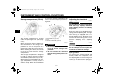
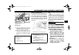
● Align the appropriate notch in the
adjusting ring with the position in-
dicator on the shock absorber.
● Use the special wrench and the
extension bar included in the own-
er’s tool kit to make the adjust-
ment.
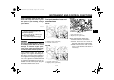
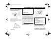
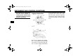
Rebound damping force
To increase the rebound damping force
and thereby harden the rebound damp-
ing, turn the adjusting screw in direction
(a). To decrease the rebound damping
force and thereby soften the rebound
damping, turn the adjusting screw in di-
rection (b).
TIP
To obtain a precise adjustment, it is ad-
visable to check the actual total number
of clicks or turns of the damping force
adjusting mechanism. This adjustment
range may not exactly match the spec-
ifications listed due to small differences
in production.
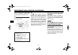
WARNING
EWA10221
This shock absorber assembly con-
tains highly pressurized nitrogen
gas. Read and understand the fol-
lowing information before handling
the shock absorber assembly.
● Do not tamper with or attempt to
open the cylinder assembly.
● Do not subject the shock ab-
sorber assembly to an open
flame or other high heat source.
This may cause the unit to ex-
plode due to excessive gas
pressure.
● Do not deform or damage the
cylinder in any way. Cylinder
damage will result in poor
damping performance.
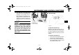
1. Spring preload adjusting ring
2. Special wrench
3. Extension bar
4. Position indicator
Spring preload setting:
Minimum (soft):
1
Standard:
3
Maximum (hard):
7
1
2
3
4
5
6
7
12 3
4
(a)
(b)
1. Rebound damping force adjusting screw
Rebound damping setting:
Minimum (soft):
12 click(s) in direction (b)*
Standard:
8 click(s) in direction (b)*
Maximum (hard):
1 click(s) in direction (b)*
* With the adjusting screw fully turned
in direction (a)
U1ECE1E0.book Page 24 Monday, August 8, 2011 11:52 AM