Read this manual carefully before operating this vehicle.
U1CAE1E0.book Page 1 Tuesday, September 13, 2011 5:02 PM EAU50920 Read this manual carefully before operating this vehicle. This manual should stay with this vehicle if it is sold. YAMAHA MOTOR ELECTRONICS CO., LTD. 1450-6, Mori, Mori-machi, Shuchi-gun, Shizuoka-ken, 437-0292 Japan DECLARATION of CONFORMITY We Company: YAMAHA MOTOR ELECTRONICS CO., LTD.
U1CAE1E0.book Page 1 Tuesday, September 13, 2011 5:02 PM INTRODUCTION EAU10102 Welcome to the Yamaha world of motorcycling! As the owner of the FZ1-S/FZ1-SA, you are benefiting from Yamaha’s vast experience and newest technology regarding the design and manufacture of high-quality products, which have earned Yamaha a reputation for dependability. Please take the time to read this manual thoroughly, so as to enjoy all advantages of your FZ1-S/FZ1-SA.
U1CAE1E0.book Page 1 Tuesday, September 13, 2011 5:02 PM IMPORTANT MANUAL INFORMATION EAU10133 Particularly important information is distinguished in this manual by the following notations: This is the safety alert symbol. It is used to alert you to potential personal injury hazards. Obey all safety messages that follow this symbol to avoid possible injury or death. WARNING NOTICE TIP A WARNING indicates a hazardous situation which, if not avoided, could result in death or serious injury.
U1CAE1E0.book Page 2 Tuesday, September 13, 2011 5:02 PM IMPORTANT MANUAL INFORMATION EAU10200 FZ1-S/FZ1-SA OWNER’S MANUAL ©2011 by Yamaha Motor Co., Ltd. 1st edition, August 2011 All rights reserved. Any reprinting or unauthorized use without the written permission of Yamaha Motor Co., Ltd. is expressly prohibited. Printed in Japan.
U1CAE1E0.book Page 1 Tuesday, September 13, 2011 5:02 PM TABLE OF CONTENTS SAFETY INFORMATION ..................1-1 DESCRIPTION ..................................2-1 Left view ..........................................2-1 Right view ........................................2-2 Controls and instruments.................2-3 INSTRUMENT AND CONTROL FUNCTIONS .......................................3-1 Immobilizer system .........................3-1 Main switch/steering lock ................
U1CAE1E0.book Page 2 Tuesday, September 13, 2011 5:02 PM TABLE OF CONTENTS Checking and lubricating the centerstand and sidestand ........6-29 Checking the front fork .................6-30 Checking the steering ...................6-30 Checking the wheel bearings .......6-31 Battery ..........................................6-31 Replacing the fuses ......................6-32 Replacing a headlight bulb ...........6-35 Replacing the tail/brake light bulb ...........................................
U1CAE1E0.book Page 1 Tuesday, September 13, 2011 5:02 PM SAFETY INFORMATION EAU10289 1 Be a Responsible Owner As the vehicle’s owner, you are responsible for the safe and proper operation of your motorcycle. Motorcycles are single-track vehicles. Their safe use and operation are dependent upon the use of proper riding techniques as well as the expertise of the operator. Every operator should know the following requirements before riding this motorcycle.
U1CAE1E0.book Page 2 Tuesday, September 13, 2011 5:02 PM SAFETY INFORMATION ● ● due to excessive speed or undercornering (insufficient lean angle for the speed). • Always obey the speed limit and never travel faster than warranted by road and traffic conditions. • Always signal before turning or changing lanes. Make sure that other motorists can see you. The posture of the operator and passenger is important for proper control.
U1CAE1E0.book Page 3 Tuesday, September 13, 2011 5:02 PM SAFETY INFORMATION ● 1 ● Do not run engine in poorly ventilated or partially enclosed areas such as barns, garages, or carports. Do not run engine outdoors where engine exhaust can be drawn into a building through openings such as windows and doors. Loading Adding accessories or cargo to your motorcycle can adversely affect stability and handling if the weight distribution of the motorcycle is changed.
U1CAE1E0.book Page 4 Tuesday, September 13, 2011 5:02 PM SAFETY INFORMATION modifications not specifically recommended by Yamaha, even if sold and installed by a Yamaha dealer. Aftermarket Parts, Accessories, and Modifications While you may find aftermarket products similar in design and quality to genuine Yamaha accessories, recognize that some aftermarket accessories or modifications are not suitable because of potential safety hazards to you or others.
U1CAE1E0.book Page 5 Tuesday, September 13, 2011 5:02 PM SAFETY INFORMATION ● 1 ● ● ● ● Check that the fuel cock (if equipped) is in the “OFF” position and that there are no fuel leaks. Point the front wheel straight ahead on the trailer or in the truck bed, and choke it in a rail to prevent movement. Shift the transmission in gear (for models with a manual transmission).
U1CAE1E0.book Page 1 Tuesday, September 13, 2011 5:02 PM DESCRIPTION EAU10410 Left view 2 1. 2. 3. 4. 5. 6. 7. 8. Front fork spring preload adjusting bolt (page 3-22) Front fork compression damping force adjusting screw (page 3-22) Air filter element (page 6-14) Main fuse (page 6-32) Fuel injection system fuse (page 6-32) Storage compartment (page 3-21) Seat lock (page 3-19) Shock absorber assembly spring preload adjusting ring (page 3-24) 9.
U1CAE1E0.book Page 2 Tuesday, September 13, 2011 5:02 PM DESCRIPTION EAU10420 Right view 1 2 3 4 5 6 7 8 2 13 1. 2. 3. 4. 5. 6. 7. 8. 12 11 10 9 Owner’s tool kit (page 6-2) Rider seat lock lever (page 3-19) Fuse box (page 6-32) Battery (page 6-31) Rear brake fluid reservoir (page 6-23) Engine oil filler cap (page 6-10) Front fork rebound damping force adjusting screw (page 3-22) Front fork spring preload adjusting bolt (page 3-22) 9. Engine oil level check window (page 6-10) 10.
U1CAE1E0.book Page 3 Tuesday, September 13, 2011 5:02 PM DESCRIPTION EAU10430 Controls and instruments 1 2 3 4 5 6 7 8 2 1. 2. 3. 4. 5. 6. 7. 8.
U1CAE1E0.book Page 1 Tuesday, September 13, 2011 5:02 PM INSTRUMENT AND CONTROL FUNCTIONS EAU10977 Immobilizer system 3 1. Code re-registering key (red bow) 2. Standard keys (black bow) This vehicle is equipped with an immobilizer system to help prevent theft by re-registering codes in the standard keys.
U1CAE1E0.book Page 2 Tuesday, September 13, 2011 5:02 PM INSTRUMENT AND CONTROL FUNCTIONS ● Keep other immobilizer system keys away from the main switch as they may cause signal interference. EAU10472 Main switch/steering lock The main switch/steering lock controls the ignition and lighting systems, and is used to lock the steering. The various positions are described below. TIP Be sure to use the standard key (black bow) for regular use of the vehicle.
U1CAE1E0.book Page 3 Tuesday, September 13, 2011 5:02 PM INSTRUMENT AND CONTROL FUNCTIONS EAU10683 LOCK The steering is locked, and all electrical systems are off. The key can be removed. To unlock the steering 1 ECA11020 NOTICE 2 Do not use the parking position for an extended length of time, otherwise the battery may discharge. To lock the steering 3 1 2 1. Push. 2. Turn. Push the key in, and then turn it to “OFF” while still pushing it. 1. Push. 2. Turn. 1.
U1CAE1E0.book Page 4 Tuesday, September 13, 2011 5:02 PM INSTRUMENT AND CONTROL FUNCTIONS EAU49391 Indicator lights and warning lights EAU11060 Neutral indicator light “ ” This indicator light comes on when the transmission is in the neutral position. EAU11080 High beam indicator light “ ” This indicator light comes on when the high beam of the headlight is switched on. EAU11254 1. 2. 3. 4. 5. 6. 7. 8.
U1CAE1E0.book Page 5 Tuesday, September 13, 2011 5:02 PM INSTRUMENT AND CONTROL FUNCTIONS ECA10021 NOTICE Do not continue to operate the engine if it is overheating. TIP ● 3 ● For radiator-fan-equipped vehicles, the radiator fan(s) automatically switch on or off according to the coolant temperature in the radiator. If the engine overheats, see page 6-43 for further instructions.
U1CAE1E0.book Page 6 Tuesday, September 13, 2011 5:02 PM INSTRUMENT AND CONTROL FUNCTIONS Display Conditions What to do Under 39 °C (Under 103 °F) Message “Lo” is displayed. OK. Go ahead with riding. 40–116 °C (104–242 °F) Coolant temperature is displayed. OK. Go ahead with riding. 117–134 °C (243–274 °F) Coolant temperature flashes. Warning light comes on. Stop the vehicle and allow it to idle until the coolant temperature goes down. If the temperature does not go down, stop the engine.
U1CAE1E0.book Page 7 Tuesday, September 13, 2011 5:02 PM INSTRUMENT AND CONTROL FUNCTIONS EAU11534 3 Engine trouble warning light “ ” This warning light comes on or flashes if a problem is detected in the electrical circuit monitoring the engine. If this occurs, have a Yamaha dealer check the self-diagnosis system. (See page 3-11 for an explanation of the self-diagnosis device.) The electrical circuit of the warning light can be checked by turning the key to “ON”.
U1CAE1E0.book Page 8 Tuesday, September 13, 2011 5:02 PM INSTRUMENT AND CONTROL FUNCTIONS EAU3942H Multi-function meter unit 1. Coolant temperature display/air intake temperature display 2. Speedometer 3. Tachometer 4. Odometer/tripmeter/fuel reserve tripmeter 5. “SELECT” button 6. “RESET” button 7. Clock 8. Fuel meter EWA12422 WARNING Be sure to stop the vehicle before making any setting changes to the multi-function meter unit.
U1CAE1E0.book Page 9 Tuesday, September 13, 2011 5:02 PM INSTRUMENT AND CONTROL FUNCTIONS ECA10031 NOTICE Do not operate the engine in the tachometer red zone. Red zone: 12000 r/min and above Clock 3 2. Push the “SELECT” button and “RESET” button together for at least two seconds. 3. When the hour digits start flashing, push the “RESET” button to set the hours. 4. Push the “SELECT” button, and the minute digits will start flashing. 5. Push the “RESET” button to set the minutes. 6.
U1CAE1E0.book Page 10 Tuesday, September 13, 2011 5:02 PM INSTRUMENT AND CONTROL FUNCTIONS Fuel meter mately 3 seconds. If this occurs, have a Yamaha dealer check the electrical circuit. Air intake temperature mode Coolant temperature mode 3 1. Fuel meter 1. Air intake temperature display The fuel meter indicates the amount of fuel in the fuel tank. The display segments of the fuel meter disappear towards “E” (Empty) as the fuel level decreases.
U1CAE1E0.book Page 11 Tuesday, September 13, 2011 5:02 PM INSTRUMENT AND CONTROL FUNCTIONS ● ● 3 When the key is turned to “ON”, the coolant temperature is automatically displayed, even if the air intake temperature was displayed prior to turning the key to “OFF”. When the air intake temperature display is selected, “A” is displayed for one second, and then the air intake temperature is displayed. Self-diagnosis device 1 2 3 1. Error code display 2. Immobilizer system indicator light 3.
U1CAE1E0.book Page 12 Tuesday, September 13, 2011 5:02 PM INSTRUMENT AND CONTROL FUNCTIONS LCD and tachometer brightness control mode 4. Push the “RESET” button to select the desired brightness level. 5. Push the “SELECT” button to confirm the selected brightness level. The display will return to the prior mode. EAU12331 Anti-theft alarm (optional) This model can be equipped with an optional anti-theft alarm by a Yamaha dealer. Contact a Yamaha dealer for more information. 3 1. 2. 3. 4.
U1CAE1E0.book Page 13 Tuesday, September 13, 2011 5:02 PM INSTRUMENT AND CONTROL FUNCTIONS EAU1234A Handlebar switches Right position. To cancel the turn signal lights, push the switch in after it has returned to the center position. Left EAU12500 Horn switch “ ” Press this switch to sound the horn. EAU12660 3 1. Engine stop switch “ 2. Start switch “ ” 1. 2. 3. 4. 5.
U1CAE1E0.book Page 14 Tuesday, September 13, 2011 5:02 PM INSTRUMENT AND CONTROL FUNCTIONS EAU12733 Hazard switch “ ” With the key in the “ON” or “ ” position, use this switch to turn on the hazard lights (simultaneous flashing of all turn signal lights). The hazard lights are used in case of an emergency or to warn other drivers when your vehicle is stopped where it might be a traffic hazard.
U1CAE1E0.book Page 15 Tuesday, September 13, 2011 5:02 PM INSTRUMENT AND CONTROL FUNCTIONS EAU26823 Brake lever EAU12941 Brake pedal EAU26794 ABS (for ABS models) The brake lever is located at the right handlebar grip. To apply the front brake, pull the lever toward the handlebar grip. The Yamaha ABS (Anti-lock Brake System) features a dual electronic control system, which acts on the front and rear brakes independently.
U1CAE1E0.book Page 16 Tuesday, September 13, 2011 5:02 PM INSTRUMENT AND CONTROL FUNCTIONS ● This ABS has a test mode which allows the owner to experience the pulsating at the brake lever or brake pedal when the ABS is operating. However, special tools are required, so please consult your Yamaha dealer when performing this test. EAU13074 2 Fuel tank cap 1 3 ECA16120 NOTICE Keep any type of magnets (including magnetic pick-up tools, magnetic screwdrivers, etc.
U1CAE1E0.book Page 17 Tuesday, September 13, 2011 5:02 PM INSTRUMENT AND CONTROL FUNCTIONS EAU13221 TIP The fuel tank cap cannot be closed unless the key is in the lock. In addition, the key cannot be removed if the cap is not properly closed and locked. EWA11091 WARNING 3 Make sure that the fuel tank cap is properly closed after filling fuel. Leaking fuel is a fire hazard. Fuel Make sure there is sufficient gasoline in the tank. EWA10881 WARNING Gasoline and gasoline vapors are extremely flammable.
U1CAE1E0.book Page 18 Tuesday, September 13, 2011 5:02 PM INSTRUMENT AND CONTROL FUNCTIONS ately. If gasoline spills on your skin, wash with soap and water. If gasoline spills on your clothing, change your clothes. EAU51170 Fuel tank breather hose and overflow hose FZ1-SA FZ1-S 2 EAU13321 Recommended fuel: Regular unleaded gasoline only Fuel tank capacity: 18.0 L (4.76 US gal, 3.96 Imp.gal) Fuel reserve amount: 3.4 L (0.90 US gal, 0.75 Imp.gal) ECA11400 NOTICE Use only unleaded gasoline.
U1CAE1E0.book Page 19 Tuesday, September 13, 2011 5:02 PM INSTRUMENT AND CONTROL FUNCTIONS EAU13445 NOTICE This vehicle is equipped with catalytic converters in the exhaust system. Use only unleaded gasoline. The use of leaded gasoline will cause unrepairable damage to the catalytic converter. EWA10862 WARNING 3 ECA10701 Catalytic converters The exhaust system is hot after operation.
U1CAE1E0.book Page 20 Tuesday, September 13, 2011 5:02 PM INSTRUMENT AND CONTROL FUNCTIONS TIP Make sure that the seats are properly secured before riding. 3 2. Remove the key. Rider seat To remove the rider seat 1. Remove the passenger seat. 2. Push the rider seat lock lever, located under the back of the rider seat, to the right as shown, and then pull the seat off. 1. Rider seat lock lever To install the rider seat 1.
U1CAE1E0.book Page 21 Tuesday, September 13, 2011 5:02 PM INSTRUMENT AND CONTROL FUNCTIONS EAU50850 Storage compartment 1 is not in the storage compartment, be sure to secure the straps to prevent losing them. EAU39671 Rear view mirrors The rear view mirrors of this vehicle can be folded forward or backward for parking in narrow spaces. Fold the mirrors back to their original position before riding. 2 3 2 1. Storage compartment The storage compartment is located under the passenger seat.
U1CAE1E0.book Page 22 Tuesday, September 13, 2011 5:02 PM INSTRUMENT AND CONTROL FUNCTIONS EAU39335 Adjusting the front fork EWA14670 WARNING load and thereby soften the suspension, turn the adjusting bolt on each fork leg in direction (b). Always adjust the spring preload on both fork legs equally, otherwise poor handling and loss of stability may result.
U1CAE1E0.book Page 23 Tuesday, September 13, 2011 5:02 PM INSTRUMENT AND CONTROL FUNCTIONS pression damping force and thereby soften the compression damping, turn the adjusting screw in direction (b). TIP Be sure to perform this adjustment on the left front fork leg. 3 1.
U1CAE1E0.book Page 24 Tuesday, September 13, 2011 5:02 PM INSTRUMENT AND CONTROL FUNCTIONS EAU39345 Adjusting the shock absorber assembly 1 2 This shock absorber assembly is equipped with a spring preload adjusting ring and a rebound damping force adjusting screw. 3 (b) (a) ECA10101 1234 NOTICE To avoid damaging the mechanism, do not attempt to turn beyond the maximum or minimum settings.
U1CAE1E0.book Page 25 Tuesday, September 13, 2011 5:02 PM INSTRUMENT AND CONTROL FUNCTIONS 3 TIP To obtain a precise adjustment, it is advisable to check the actual total number of clicks or turns of the damping force adjusting mechanism. This adjustment range may not exactly match the specifications listed due to small differences in production. ● Do not dispose of a damaged or worn-out shock absorber assembly yourself. Take the shock absorber assembly to a Yamaha dealer for any service.
U1CAE1E0.book Page 26 Tuesday, September 13, 2011 5:02 PM INSTRUMENT AND CONTROL FUNCTIONS EAU41941 EAU15305 EXUP system Sidestand This model is equipped with Yamaha’s EXUP (EXhaust Ultimate Power valve) system. This system boosts engine power by means of a valve that regulates the inner diameter of the exhaust pipe. The EXUP system valve is constantly adjusted in accordance with the engine speed by a computer-controlled servomotor. The sidestand is located on the left side of the frame.
U1CAE1E0.book Page 27 Tuesday, September 13, 2011 5:02 PM INSTRUMENT AND CONTROL FUNCTIONS EAU44902 Ignition circuit cut-off system 3 The ignition circuit cut-off system (comprising the sidestand switch, clutch switch and neutral switch) has the following functions. ● It prevents starting when the transmission is in gear and the sidestand is up, but the clutch lever is not pulled. ● It prevents starting when the transmission is in gear and the clutch lever is pulled, but the sidestand is still down.
U1CAE1E0.book Page 28 Tuesday, September 13, 2011 5:02 PM INSTRUMENT AND CONTROL FUNCTIONS With the engine turned off: 1. Move the sidestand down. 2. Make sure that the engine stop switch is set to “ 3. Turn the key on. 4. Shift the transmission into the neutral position. 5. Push the start switch. Does the engine start? WARNING • The vehicle must be placed on the center- ”. stand during this inspection. • If a malfunction is noted, have a Yamaha dealer check the system before riding.
U1CAE1E0.book Page 1 Tuesday, September 13, 2011 5:02 PM FOR YOUR SAFETY – PRE-OPERATION CHECKS EAU15596 Inspect your vehicle each time you use it to make sure the vehicle is in safe operating condition. Always follow the inspection and maintenance procedures and schedules described in the Owner’s Manual. EWA11151 WARNING Failure to inspect or maintain the vehicle properly increases the possibility of an accident or equipment damage. Do not operate the vehicle if you find any problem.
U1CAE1E0.book Page 2 Tuesday, September 13, 2011 5:02 PM FOR YOUR SAFETY – PRE-OPERATION CHECKS ITEM CHECKS PAGE Rear brake • • • • • • • Check operation. If soft or spongy, have Yamaha dealer bleed hydraulic system. Check brake pads for wear. Replace if necessary. Check fluid level in reservoir. If necessary, add specified brake fluid to specified level. Check hydraulic system for leakage. Clutch • • • • Check operation. Lubricate cable if necessary. Check lever free play. Adjust if necessary.
U1CAE1E0.book Page 3 Tuesday, September 13, 2011 5:02 PM FOR YOUR SAFETY – PRE-OPERATION CHECKS ITEM CHECKS PAGE Chassis fasteners • Make sure that all nuts, bolts and screws are properly tightened. • Tighten if necessary. — Instruments, lights, signals and switches • Check operation. • Correct if necessary. — Sidestand switch • Check operation of ignition circuit cut-off system. • If system is not working correctly, have Yamaha dealer check vehicle.
U1CAE1E0.book Page 1 Tuesday, September 13, 2011 5:02 PM OPERATION AND IMPORTANT RIDING POINTS EAU15951 EAU47150 EAU44728 Starting the engine Read the Owner’s Manual carefully to become familiar with all controls. If there is a control or function you do not understand, ask your Yamaha dealer. EWA10271 WARNING Failure to familiarize yourself with the controls can lead to loss of control, which could cause an accident or injury.
U1CAE1E0.book Page 2 Tuesday, September 13, 2011 5:02 PM OPERATION AND IMPORTANT RIDING POINTS ECA11833 EAU16671 Shifting NOTICE ● If a warning or indicator light does not come on initially when the key is turned to “ON”, or if a warning or indicator light remains on, see page 3-4 for the corresponding warning and indicator light circuit check. 5 2. Shift the transmission into the neutral position. The neutral indicator light should come on.
U1CAE1E0.book Page 3 Tuesday, September 13, 2011 5:02 PM OPERATION AND IMPORTANT RIDING POINTS EAU16810 Tips for reducing fuel consumption Fuel consumption depends largely on your riding style. Consider the following tips to reduce fuel consumption: ● Shift up swiftly, and avoid high engine speeds during acceleration. ● Do not rev the engine while shifting down, and avoid high engine speeds with no load on the engine. ● Turn the engine off instead of letting it idle for an extended length of time (e.g.
U1CAE1E0.book Page 4 Tuesday, September 13, 2011 5:02 PM OPERATION AND IMPORTANT RIDING POINTS EAU17213 Parking When parking, stop the engine, and then remove the key from the main switch. EWA10311 WARNING ● 5 ● ● Since the engine and exhaust system can become very hot, park in a place where pedestrians or children are not likely to touch them and be burned. Do not park on a slope or on soft ground, otherwise the vehicle may overturn, increasing the risk of a fuel leak and fire.
U1CAE1E0.book Page 1 Tuesday, September 13, 2011 5:02 PM PERIODIC MAINTENANCE AND ADJUSTMENT EAU17244 EWA15122 EAU17302 WARNING Periodic inspection, adjustment, and lubrication will keep your vehicle in the safest and most efficient condition possible. Safety is an obligation of the vehicle owner/operator. The most important points of vehicle inspection, adjustment, and lubrication are explained on the following pages.
U1CAE1E0.book Page 2 Tuesday, September 13, 2011 5:02 PM PERIODIC MAINTENANCE AND ADJUSTMENT EAU17542 Owner’s tool kit 1. Owner’s tool kit 6 The owner’s tool kit is located under the passenger seat. (See page 3-19.) The service information included in this manual and the tools provided in the owner’s tool kit are intended to assist you in the performance of preventive maintenance and minor repairs.
U1CAE1E0.book Page 3 Tuesday, September 13, 2011 5:02 PM PERIODIC MAINTENANCE AND ADJUSTMENT EAU46861 TIP ● ● ● The annual checks must be performed every year, except if a kilometer-based maintenance, or for the UK, a mileage-based maintenance, is performed instead. From 50000 km (30000 mi), repeat the maintenance intervals starting from 10000 km (6000 mi). Items marked with an asterisk should be performed by a Yamaha dealer as they require special tools, data and technical skills.
U1CAE1E0.book Page 4 Tuesday, September 13, 2011 5:02 PM PERIODIC MAINTENANCE AND ADJUSTMENT EAU1770C General maintenance and lubrication chart ODOMETER READING NO. 1 2 ITEM CHECK OR MAINTENANCE JOB 1000 km (600 mi) 10000 km (6000 mi) 20000 km (12000 mi) 30000 km (18000 mi) 40000 km (24000 mi) ANNUAL CHECK √ Air filter element • Replace. Clutch • Check operation. • Adjust. √ √ √ √ √ • Check operation, fluid level and vehicle for fluid leakage.
U1CAE1E0.book Page 5 Tuesday, September 13, 2011 5:02 PM PERIODIC MAINTENANCE AND ADJUSTMENT ODOMETER READING NO. 10 ITEM Drive chain 11 * Steering bearings 12 * Chassis fasteners CHECK OR MAINTENANCE JOB • Check chain slack, alignment and condition. • Adjust and lubricate chain with a special O-ring chain lubricant thoroughly. • Check bearing play and steering for roughness.
U1CAE1E0.book Page 6 Tuesday, September 13, 2011 5:02 PM PERIODIC MAINTENANCE AND ADJUSTMENT ODOMETER READING NO. ITEM 21 * Rear suspension relay arm and connecting arm pivoting points • Check operation. 22 Engine oil • Change. • Check oil level and vehicle for oil leakage. √ 23 Engine oil filter cartridge • Replace. √ 24 * Cooling system 6 CHECK OR MAINTENANCE JOB • Check coolant level and vehicle for coolant leakage. Front and rear brake switches • Check operation.
U1CAE1E0.book Page 7 Tuesday, September 13, 2011 5:02 PM PERIODIC MAINTENANCE AND ADJUSTMENT EAU18680 TIP ● ● Air filter • This model’s air filter is equipped with a disposable oil-coated paper element, which must not be cleaned with compressed air to avoid damaging it. • The air filter element needs to be replaced more frequently when riding in unusually wet or dusty areas. Hydraulic brake service • Regularly check and, if necessary, correct the brake fluid level.
U1CAE1E0.book Page 8 Tuesday, September 13, 2011 5:02 PM PERIODIC MAINTENANCE AND ADJUSTMENT EAU18771 Removing and installing panels The panels shown need to be removed to perform some of the maintenance jobs described in this chapter. Refer to this section each time a panel needs to be removed and installed. 1. Panel C EAU40031 Panels A and B To remove a panel Remove the bolts and the screws, and then pull the panel off as shown. 6 1. Panel A 2.
U1CAE1E0.book Page 9 Tuesday, September 13, 2011 5:02 PM PERIODIC MAINTENANCE AND ADJUSTMENT FZ1-SA EAU19652 Checking the spark plugs The spark plugs are important engine components, which should be checked periodically, preferably by a Yamaha dealer. Since heat and deposits will cause any spark plug to slowly erode, they should be removed and checked in accordance with the periodic maintenance and lubrication chart. In addition, the condition of the spark plugs can reveal the condition of the engine.
U1CAE1E0.book Page 10 Tuesday, September 13, 2011 5:02 PM PERIODIC MAINTENANCE AND ADJUSTMENT Before installing a spark plug, the spark plug gap should be measured with a wire thickness gauge and, if necessary, adjusted to specification. EAU19879 TIP If a torque wrench is not available when installing a spark plug, a good estimate of the correct torque is 1/4–1/2 turn past finger tight. However, the spark plug should be tightened to the specified torque as soon as possible.
U1CAE1E0.book Page 11 Tuesday, September 13, 2011 5:02 PM PERIODIC MAINTENANCE AND ADJUSTMENT 4. Remove the engine oil filler cap, the engine oil drain bolt and its gasket to drain the oil from the crankcase. 2 1 1. 2. 3. 4. Engine oil filler cap Engine oil level check window Maximum level mark Minimum level mark 4. If the engine oil is below the minimum level mark, add sufficient oil of the recommended type to raise it to the correct level.
U1CAE1E0.book Page 12 Tuesday, September 13, 2011 5:02 PM PERIODIC MAINTENANCE AND ADJUSTMENT Recommended engine oil: See page 8-1. Oil quantity: Without oil filter cartridge replacement: 2.90 L (3.07 US qt, 2.55 Imp.qt) With oil filter cartridge replacement: 3.10 L (3.28 US qt, 2.73 Imp.qt) 1. O-ring TIP Make sure that the O-ring is properly seated. 6 7. Install the new oil filter cartridge with an oil filter wrench, and then tighten it to the specified torque with a torque wrench. 1.
U1CAE1E0.book Page 13 Tuesday, September 13, 2011 5:02 PM PERIODIC MAINTENANCE AND ADJUSTMENT 10. Start the engine, and then let it idle for several minutes while checking it for oil leakage. If oil is leaking, immediately turn the engine off and check for the cause. TIP After the engine is started, the engine oil level warning light should go off if the oil level is sufficient.
U1CAE1E0.book Page 14 Tuesday, September 13, 2011 5:02 PM PERIODIC MAINTENANCE AND ADJUSTMENT If water has been used instead of coolant, replace it with coolant as soon as possible, otherwise the cooling system will not be protected against frost and corrosion. If water has been added to the coolant, have a Yamaha dealer check the antifreeze content of the coolant as soon as possible, otherwise the effectiveness of the coolant will be reduced.
U1CAE1E0.book Page 15 Tuesday, September 13, 2011 5:02 PM PERIODIC MAINTENANCE AND ADJUSTMENT 1. Fuel tank bolt 5. Lift the front of the fuel tank, and carefully tilt it back and away from the air filter case, but do not disconnect the fuel hoses. WARNING! Make sure that the fuel tank is well supported. Do not tilt or pull the fuel tank too much, otherwise the fuel hoses may come loose, which could cause fuel leakage and a fire hazard. [EWA10411] 6.
U1CAE1E0.book Page 16 Tuesday, September 13, 2011 5:02 PM PERIODIC MAINTENANCE AND ADJUSTMENT hose and the fuel tank overflow hose in the original position. WARNING! Before placing the fuel tank in the original position, make sure that the fuel hoses are not damaged. If any fuel hose is damaged, do not start the engine but have a Yamaha dealer replace the hose, otherwise fuel may leak, creating a fire hazard. [EWA11361] FZ1-S FZ1-SA 13. Install the panels. 14. Install the rider seat. 2 1 1.
U1CAE1E0.book Page 17 Tuesday, September 13, 2011 5:02 PM PERIODIC MAINTENANCE AND ADJUSTMENT EAU34301 Adjusting the engine idling speed The engine idling speed must be checked and, if necessary, adjusted as follows at the intervals specified in the periodic maintenance and lubrication chart. The engine should be warm before making this adjustment. Check the engine idling speed and, if necessary, adjust it to specification by turning the idle adjusting screw.
U1CAE1E0.book Page 18 Tuesday, September 13, 2011 5:02 PM PERIODIC MAINTENANCE AND ADJUSTMENT EAU21401 EAU21775 Valve clearance Tires The valve clearance changes with use, resulting in improper air-fuel mixture and/or engine noise. To prevent this from occurring, the valve clearance must be adjusted by a Yamaha dealer at the intervals specified in the periodic maintenance and lubrication chart.
U1CAE1E0.book Page 19 Tuesday, September 13, 2011 5:02 PM PERIODIC MAINTENANCE AND ADJUSTMENT Tire inspection EWA10471 Tire information WARNING ● ● 1. Tire sidewall 2. Tire tread depth The tires must be checked before each ride. If the center tread depth reaches the specified limit, if the tire has a nail or glass fragments in it, or if the sidewall is cracked, have a Yamaha dealer replace the tire immediately. ● Have a Yamaha dealer replace excessively worn tires.
U1CAE1E0.book Page 20 Tuesday, September 13, 2011 5:02 PM PERIODIC MAINTENANCE AND ADJUSTMENT ● Use only the tire valves and valve cores listed below to avoid tire deflation during a high-speed ride. After extensive tests, only the tires listed below have been approved for this model by Yamaha Motor Co., Ltd.
U1CAE1E0.book Page 21 Tuesday, September 13, 2011 5:02 PM PERIODIC MAINTENANCE AND ADJUSTMENT EAU22081 Adjusting the clutch lever free play EAU37913 TIP If the specified free play cannot be obtained as described above or if the clutch does not operate correctly, have a Yamaha dealer check the internal clutch mechanism. 1. Clutch lever free play adjusting bolt 2. Clutch lever free play Checking the brake lever free play 1 1.
U1CAE1E0.book Page 22 Tuesday, September 13, 2011 5:02 PM PERIODIC MAINTENANCE AND ADJUSTMENT braking performance, which may result in loss of control and an accident. EAU50750 Brake light switches (for ABS models) EAU50760 Brake light switches (for nonABS models) The brake light, which is activated by the brake pedal and brake lever, should come on just before braking takes effect. If necessary, have a Yamaha dealer adjust the brake light switches. 1. Rear brake light switch 2.
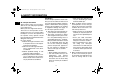
U1CAE1E0.book Page 23 Tuesday, September 13, 2011 5:02 PM PERIODIC MAINTENANCE AND ADJUSTMENT Checking the front and rear brake pads the point that a wear indicator almost touches the brake disc, have a Yamaha dealer replace the brake pads as a set. The front and rear brake pads must be checked for wear at the intervals specified in the periodic maintenance and lubrication chart.
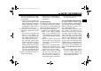
U1CAE1E0.book Page 24 Tuesday, September 13, 2011 5:02 PM PERIODIC MAINTENANCE AND ADJUSTMENT Rear brake (FZ1-S) sult in vapor lock, and dirt may clog the ABS hydraulic unit valves. Specified brake fluid: DOT 4 EWA16010 ECA17640 WARNING 1. Minimum level mark Rear brake (FZ1-SA) 6 1. Minimum level mark TIP The rear brake fluid reservoir is located behind panel C. (See page 6-8.) NOTICE Improper maintenance can result in loss of braking ability.
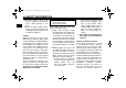
U1CAE1E0.book Page 25 Tuesday, September 13, 2011 5:02 PM PERIODIC MAINTENANCE AND ADJUSTMENT EAU22731 EAU22760 Changing the brake fluid Drive chain slack Have a Yamaha dealer change the brake fluid at the intervals specified in the TIP after the periodic maintenance and lubrication chart. In addition, have the oil seals of the master cylinders and calipers as well as the brake hoses replaced at the intervals listed below or whenever they are damaged or leaking. ● Oil seals: Replace every two years.
U1CAE1E0.book Page 26 Tuesday, September 13, 2011 5:02 PM PERIODIC MAINTENANCE AND ADJUSTMENT EAU23025 TIP Using the alignment marks on each side of the swingarm, make sure that both drive chain pullers are in the same position for proper wheel alignment. 1 23 (a) Tightening torques: Axle nut: 150 Nm (15 m·kgf, 108 ft·lbf) Locknut: 16 Nm (1.6 m·kgf, 12 ft·lbf) 7. Make sure that the drive chain pullers are in the same position, the drive chain slack is correct, and the drive chain moves smoothly.
U1CAE1E0.book Page 27 Tuesday, September 13, 2011 5:02 PM PERIODIC MAINTENANCE AND ADJUSTMENT may contain substances that could damage the O-rings. [ECA11111] EAU23095 EAU23114 Checking and lubricating the cables Checking and lubricating the throttle grip and cable The operation of all control cables and the condition of the cables should be checked before each ride, and the cables and cable ends should be lubricated if necessary.
U1CAE1E0.book Page 28 Tuesday, September 13, 2011 5:02 PM PERIODIC MAINTENANCE AND ADJUSTMENT EAU44273 Checking and lubricating the brake and shift pedals EAU23143 Recommended lubricant: Lithium-soap-based grease Checking and lubricating the brake and clutch levers The operation of the brake and shift pedals should be checked before each ride, and the pedal pivots should be lubricated if necessary.
U1CAE1E0.book Page 29 Tuesday, September 13, 2011 5:02 PM PERIODIC MAINTENANCE AND ADJUSTMENT EAU23213 Recommended lubricants: Brake lever: Silicone grease Clutch lever: Lithium-soap-based grease Checking and lubricating the centerstand and sidestand The operation of the centerstand and sidestand should be checked before each ride, and the pivots and metal-tometal contact surfaces should be lubricated if necessary.
U1CAE1E0.book Page 30 Tuesday, September 13, 2011 5:02 PM PERIODIC MAINTENANCE AND ADJUSTMENT EAU23272 EAU45511 Checking the front fork Checking the steering The condition and operation of the front fork must be checked as follows at the intervals specified in the periodic maintenance and lubrication chart. Worn or loose steering bearings may cause danger. Therefore, the operation of the steering must be checked as follows at the intervals specified in the periodic maintenance and lubrication chart.
U1CAE1E0.book Page 31 Tuesday, September 13, 2011 5:02 PM PERIODIC MAINTENANCE AND ADJUSTMENT EAU23291 EAU50210 Checking the wheel bearings Battery The front and rear wheel bearings must be checked at the intervals specified in the periodic maintenance and lubrication chart. If there is play in the wheel hub or if the wheel does not turn smoothly, have a Yamaha dealer check the wheel bearings. 1. Positive battery lead (red) 2. Negative battery lead (black) 3.
U1CAE1E0.book Page 32 Tuesday, September 13, 2011 5:02 PM PERIODIC MAINTENANCE AND ADJUSTMENT battery tends to discharge more quickly if the vehicle is equipped with optional electrical accessories. ECA16521 NOTICE To charge a VRLA (Valve Regulated Lead Acid) battery, a special (constant-voltage) battery charger is required. Using a conventional battery charger will damage the battery. 6 To store the battery 1.
U1CAE1E0.book Page 33 Tuesday, September 13, 2011 5:02 PM PERIODIC MAINTENANCE AND ADJUSTMENT FZ1-S FZ1-SA FZ1-SA 1. 2. 3. 4. 5. 1. 2. 3. 4. 1. 2. 3. 4. 6. 7. 8. 9.
U1CAE1E0.book Page 34 Tuesday, September 13, 2011 5:02 PM PERIODIC MAINTENANCE AND ADJUSTMENT 2. Unhook the battery band, and then remove the battery cover. 1. Battery band 2. Battery cover 6 3. Remove the starter relay cover by pulling it upward. 1 2 3 1. Starter relay cover 2. Fuel injection system fuse 3. Fuel injection system spare fuse 4. Remove the blown fuse, and then install a new fuse of the specified amperage.
U1CAE1E0.book Page 35 Tuesday, September 13, 2011 5:02 PM PERIODIC MAINTENANCE AND ADJUSTMENT EAU23934 Replacing a headlight bulb This model is equipped with halogen bulb headlights. If a headlight bulb burns out, replace it as follows. ECA10650 NOTICE Take care not to damage the following parts: ● Headlight bulb Do not touch the glass part of the headlight bulb to keep it free from oil, otherwise the transparency of the glass, the luminosity of the bulb, and the bulb life will be adversely affected.
U1CAE1E0.book Page 36 Tuesday, September 13, 2011 5:02 PM PERIODIC MAINTENANCE AND ADJUSTMENT EAU24115 Replacing the tail/brake light bulb 1. Remove the passenger seat. (See page 3-19.) 2. Remove the tail/brake light bulb socket (together with the bulb) by turning it counterclockwise. EAU24204 Replacing a turn signal light bulb 1. Remove the turn signal light lens by removing the screw. 1. Turn signal light lens 2. Screw 6 1. Tail/brake light bulb socket 3.
U1CAE1E0.book Page 37 Tuesday, September 13, 2011 5:02 PM PERIODIC MAINTENANCE AND ADJUSTMENT EAU27014 Replacing an auxiliary light bulb 1 2 1. License plate light bulb 2. License plate light bulb socket 3. Remove the burnt-out bulb by pulling it out. 4. Insert a new bulb into the socket. 5. Install the socket (together with the bulb) by pushing it in. 6. Install the license plate light unit by installing the screws. This model is equipped with two auxiliary lights.
U1CAE1E0.book Page 38 Tuesday, September 13, 2011 5:02 PM PERIODIC MAINTENANCE AND ADJUSTMENT EAU44791 Front wheel (for non-ABS models) EWA14840 WARNING For the ABS model, have a Yamaha dealer remove and install the wheel. 3 2 1 EAU40062 To remove the front wheel EWA10821 WARNING To avoid injury, securely support the vehicle so there is no danger of it falling over. 6 1. Loosen the front wheel axle pinch bolt, then the wheel axle and the brake caliper bolts. 1. Front wheel axle pinch bolt 2.
U1CAE1E0.book Page 39 Tuesday, September 13, 2011 5:02 PM PERIODIC MAINTENANCE AND ADJUSTMENT 4. Install the brake hose holder on each side by installing the bolt and nut. 5. Take the vehicle off the centerstand so that the front wheel is on the ground, and then put the sidestand down. 6. Tighten the wheel axle, the front wheel axle pinch bolt, and the brake caliper bolts to the specified torques. Tightening torques: Wheel axle: 72 Nm (7.2 m·kgf, 52 ft·lbf) Front wheel axle pinch bolt: 23 Nm (2.
U1CAE1E0.book Page 40 Tuesday, September 13, 2011 5:02 PM PERIODIC MAINTENANCE AND ADJUSTMENT ● The drive chain cannot be disassembled. 7. While supporting the brake caliper bracket, pull the wheel axle out, and then remove the wheel. NOTICE: Do not apply the brake after the wheel has been removed together with the brake disc, otherwise the brake pads will be forced shut. [ECA11071] TIP ● ● Make sure that the slot in the brake caliper bracket is fit over the retainer on the swingarm.
U1CAE1E0.book Page 41 Tuesday, September 13, 2011 5:02 PM PERIODIC MAINTENANCE AND ADJUSTMENT EAU25871 Troubleshooting Although Yamaha motorcycles receive a thorough inspection before shipment from the factory, trouble may occur during operation. Any problem in the fuel, compression, or ignition systems, for example, can cause poor starting and loss of power. The following troubleshooting charts represent quick and easy procedures for checking these vital systems yourself.
U1CAE1E0.book Page 42 Tuesday, September 13, 2011 5:02 PM PERIODIC MAINTENANCE AND ADJUSTMENT EAU42503 Troubleshooting charts Starting problems or poor engine performance 1. Fuel There is enough fuel. Check the compression. There is no fuel. Supply fuel. There is compression. Check the ignition. There is no compression. Have a Yamaha dealer check the vehicle. Check the fuel level in the fuel tank. The engine does not start. Check the compression. 2. Compression Operate the electric starter.
U1CAE1E0.book Page 43 Tuesday, September 13, 2011 5:02 PM PERIODIC MAINTENANCE AND ADJUSTMENT Engine overheating EWAT1040 WARNING ● ● Do not remove the radiator cap when the engine and radiator are hot. Scalding hot fluid and steam may be blown out under pressure, which could cause serious injury. Be sure to wait until the engine has cooled. Place a thick rag, like a towel, over the radiator cap, and then slowly rotate the cap counterclockwise to the detent to allow any residual pressure to escape.
U1CAE1E0.book Page 1 Tuesday, September 13, 2011 5:02 PM MOTORCYCLE CARE AND STORAGE EAU37833 Matte color caution ECA15192 NOTICE Some models are equipped with matte colored finished parts. Be sure to consult a Yamaha dealer for advice on what products to use before cleaning the vehicle. Using a brush, harsh chemical products or cleaning compounds when cleaning these parts will scratch or damage their surface. Wax also should not be applied to any matte colored finished parts.
U1CAE1E0.book Page 2 Tuesday, September 13, 2011 5:02 PM MOTORCYCLE CARE AND STORAGE ● ● ● off any detergent residue using plenty of water, as it is harmful to plastic parts. Do not use any harsh chemical products on plastic parts. Be sure to avoid using cloths or sponges which have been in contact with strong or abrasive cleaning products, solvent or thinner, fuel (gasoline), rust removers or inhibitors, brake fluid, antifreeze or electrolyte.
U1CAE1E0.book Page 3 Tuesday, September 13, 2011 5:02 PM MOTORCYCLE CARE AND STORAGE 4. To prevent corrosion, it is recommended to apply a corrosion protection spray on all metal, including chrome- and nickel-plated, surfaces. 5. Use spray oil as a universal cleaner to remove any remaining dirt. 6. Touch up minor paint damage caused by stones, etc. 7. Wax all painted surfaces. 8. Let the motorcycle dry completely before storing or covering it.
U1CAE1E0.book Page 4 Tuesday, September 13, 2011 5:02 PM MOTORCYCLE CARE AND STORAGE 2. Fill up the fuel tank and add fuel stabilizer (if available) to prevent the fuel tank from rusting and the fuel from deteriorating. 3. Perform the following steps to protect the cylinders, piston rings, etc. from corrosion. a. Remove the spark plug caps and spark plugs. b. Pour a teaspoonful of engine oil into each spark plug bore. c.
U1CAE1E0.book Page 1 Tuesday, September 13, 2011 5:02 PM SPECIFICATIONS Dimensions: Overall length: 2140 mm (84.3 in) Overall width: 770 mm (30.3 in) Overall height: 1205 mm (47.4 in) Seat height: 815 mm (32.1 in) Wheelbase: 1460 mm (57.5 in) Ground clearance: 135 mm (5.31 in) Minimum turning radius: 3000 mm (118.
U1CAE1E0.book Page 2 Tuesday, September 13, 2011 5:02 PM SPECIFICATIONS 2nd: 2.063 (33/16) 3rd: 1.762 (37/21) 4th: 1.522 (35/23) 5th: 1.350 (27/20) 6th: 1.208 (29/24) Chassis: Frame type: Diamond Caster angle: 25.00 ° Trail: 109 mm (4.
U1CAE1E0.book Page 3 Tuesday, September 13, 2011 5:02 PM SPECIFICATIONS Charging system: AC magneto Battery: Model: YTZ14S Voltage, capacity: 12 V, 11.2 Ah Headlight: Bulb type: Halogen bulb Bulb voltage, wattage × quantity: 8 Headlight: 12 V, 60 W/55 W × 2 Tail/brake light: 12 V, 5.0 W/21.0 W × 1 Front turn signal light: 12 V, 10.0 W × 2 Rear turn signal light: 12 V, 10.0 W × 2 Auxiliary light: 12 V, 5.0 W × 2 License plate light: 12 V, 5.
U1CAE1E0.book Page 1 Tuesday, September 13, 2011 5:02 PM CONSUMER INFORMATION EAU48612 Identification numbers EAU26400 EAU26470 Vehicle identification number Model label 1. Vehicle identification number 1. Model label The vehicle identification number is stamped into the steering head pipe. Record this number in the space provided. The model label is affixed to the frame under the rider seat. (See page 3-19.) Record the information on this label in the space provided.
U1CAE1E0.book Page 1 Tuesday, September 13, 2011 5:02 PM INDEX A ABS (for ABS models) .......................... 3-15 ABS warning light (for ABS models) ....... 3-7 Air filter element, replacing ................... 6-14 Anti-theft alarm (optional)...................... 3-12 Auxiliary light bulb, replacing ................ 6-37 Drive chain slack .................................. 6-25 Engine break-in ...................................... 5-3 Engine idling speed ..............................
U1CAE1E0.book Page 2 Tuesday, September 13, 2011 5:02 PM INDEX Throttle grip and cable, checking and lubricating..................... 6-27 Throttle grip free play, checking ........... 6-17 Tires...................................................... 6-18 Tool kit .................................................... 6-2 Troubleshooting.................................... 6-41 Troubleshooting charts ......................... 6-42 Turn signal indicator lights ......................
A5-yoko_Blank.
A5-yoko_Blank.
PRINTED ON RECYCLED PAPER PRINTED IN JAPAN 2011.12-0.