Active Servo Technology DISC CHANGE MINI COMPONENT SYSTEM GX–70 GX–7 OPEN/CLOSE 1 PTY SEE K Y LA DISP T STAR 2 DISC IT ED DE 3 MO FRE PROGRAM PRESET/TUNINGBAND MUSIC Q PS/P TY/R RAND T/CT REPE AT OM VOLUME A/B/C/D/E CD DOWN INPUT MEMORY UP TAPE 1/2 REC/PAUSE MODE NORMAL HIGH DOLBY NR POWER UP INPUT DOWN USER DUBBING PHONES TIMER REC MEMORY AUTO/MAN’L Active Servo Technology TIMER TIME ADJ HOUR PLAYBACK MIN 1 2 REC/PLAYBACK DOLBY B NR EJECT EJECT Active Serv
SAFETY INSTRUCTIONS 7 Wall or Ceiling Mounting – The unit should be mounted to a wall or ceiling only as recommended by the manufacturer. 8 Ventilation – The unit should be situated so that its location or position does not interfere with its proper ventilation.
19 For US customers only: EXAMPLE OF ANTENNA GROUNDING Outdoor Antenna Grounding – If an outside antenna is connected to this unit, be sure the antenna system is grounded so as to provide some protection against voltage surges and built-up static charges.
SUPPLIED ACCESSORIES ACCESSOIRES FOURNIS ● ● Remote control transmitter Télécommande After unpacking, check that the following parts are contained. Après le déballage, vérifier que les pièces suivantes sont incluses.
1 1 345 67 89= A B 2 TAPE 1 PROGRAM USER NOR TEST PRO LOGIC HALL ARENA 1 2 PHANTOM 3 4 TIMER SLEEP 3 STEREO MUSIC ROCK BLUES RAP JAZZ C STEREO TUNED MEMORY AUTO PTY HOLD PRESET 100 350 VOLUME MHz 1K 3.
2 MUSIC ROCK PROGRAM TAPE 1 USER J H I G RANDOM 1 2 3 4 5 6 ARENA 7 8 9 10 11 12 TOTAL REM 13 14 15 OVER 15 TRACK 100 350 EDIT PROG A B S F REP 1K 3.
3 R S T U VW MUSIC ROCK 100 350 PROGRAM DUBBING REC TAPE 1 2 NOR HIGH USER ARENA 1 2 3 4 5 6 7 8 9 10 11 12 B 13 14 15 OVER 15 VOLUME 1K 3.
4 Front speakers Enceintes avant , , , , , , , , , ,,,,,,,,,,, ,,,,,,,,,,, ,,,,,,,,,,, NX-GX70 Active Servo Active Servo Technology Technology i NX-C70 Center speaker Enceinte centrale NX-E70 Rear speakers Enceintes arrière j j 8
1 5 2 3 4 1 2 CD 3 1 2 3 6 7 8 6 7 8 7 4 4 5 9 0 A B C D E PROG TAPE EDIT +I0 MODE REPEAT RANDOM OPEN/CLOSE TUNER DISC SKIP CENTER/REAR /DELAY TEST LEVEL PLAY FLAT MUSIC 2 CD 3 4 1 2 3 4 6 7 8 5 5 PRESET 6 7 8 9 0 A B C D E TAPE EDIT +I0 S 5 PRESET TIME REC/PAUSE TAPE 1/2 5 6 G 1 STOP PLAY/PAUSE STOP PLAY TAPE PROGRAM USER F H E I D C B J TIME PROG MODE REPEAT RANDOM OPEN/CLOSE TUNER STOP DISC SKIP K L M PLAY/PAUSE
8 POWER HIGH CUT 40 Hz VOLUME 140 Hz 0 10 Center speaker Enceinte centrale Subwoofer system Subwoofer de Traitement SPEAKERS CENTER/REAR REAR R SUBWOOFER CENTER R L L REAR VIDEO SIGNAL OUT MONITOR OUT DO NOT CONNECT THIS UNIT TO SPEAKERS OTHER THAN NX-C70 (CENTER) OR NX-E70 (REAR). OUT VCR IN Rear speakers LD/TV Enceintes arrière OUT MD/AUX R L IN R SINCE THIS UNIT HAS AN ACTIVE SERVO CIRCUIT BUILT–IN. DO NOT CONNECT IT TO SPEAKERS OTHER THAN NX–GX70.
9 Monitor TV Moniteur TV VIDEO IN AUDIO OUT VIDEO OUT LD player etc. Lecteur de disque laser, etc. SUBWOOFER VIDEO SIGNAL MONITOR OUT OUT VIDEO IN OUT AUDIO IN VCR VIDEO OUT IN AUDIO OUT LD/TV OUT Video cassette recorder Magnétoscope MD/AUX IN R L LINE OUT LINE IN AUDIO SIGNAL ANTENNA FM GND AM 75Ω UNBAL. SPEAKERS CENTER/REAR CENTER MODE NORMAL PHANTOM REAR R SUBWOOFER L REAR VIDEO SIGNAL OUT DAT, MD recorder, etc.
@ C DISC CHANGE MINI COMPONENT SYSTEM GX–70 OPEN/CLOSE 1 SEEK PTY T 2 DISC ANTENNA STAR 3 /RT/CT PTY Q PS/ FM GND FRE PROGRAM AM RA PRESET/TUNING/BAND MUSIC 75Ω UNBAL.
ENGLISH English INTRODUCTION Thank you for purchasing this YAMAHA product. We hope it will give you many years of trouble-free enjoyment. For the best performance, read this manual carefully. It will guide you in operating your YAMAHA product. CONTENTS Page Page PRECAUTIONS ..................................................................2-3 RECEIVING RDS STATIONS FEATURES.........................................................................4-5 (U.K. and Europe models only).......................
PRECAUTIONS: READ THIS BEFORE OPERATING YOUR UNIT ■ This system is designed for using the provided Active Servo Processing Speaker System for front speakers. Therefore, do not attempt to connect other conventional speakers to the FRONT SPEAKERS terminals of this system. ■ Although the cassette deck’s record/playback heads used in this unit are high quality heads with outstanding reproduction characteristics, they can become dirty through the use of old tapes or from dust accumulation over time.
WARNING IMPORTANT Please record the serial number of this unit in the space below. DANGER Invisible laser radiation when open and interlock failed or defeated. Avoid direct exposure to beam. Serial No.: The serial number is located on the rear of the unit. Retain this Owner’s Manual in a safe place for future reference. CAUTION Use of controls or adjustments or performance of procedures other than those specified herein may result in hazardous radiation exposure.
FEATURES The System Compact Disc Player ● 5 Speaker Multi-Channel Audio System Including Two Front Speakers, One Center Speaker and Two Rear Speakers ● 3-Disc Carousel Type CD Changer ● Active Servo Processing Front Speaker System (NX-GX70) ● PLAYXCHANGE; Disc Changing Capability while Playing Back Another ● Free-Standing/Wall Mounting Type Rear Speaker System (NX-E70) ● 20-Track Random Access Programmable CD Playback ● Remote Control Capability ● Single Track/Entire Disc/All Disc Repeat Play ● C
Sound Field Processor Including Dolby Pro Logic Surround Decoder Graphic Equalizer ● 5-Band Adjustable Graphic Equalizer ● 2 Programs for Dolby Surround Decoding (DOLBY PRO LOGIC and DOLBY 3 STEREO) 2 Programs for Sound Field Processing (HALL and ARENA) [3-Karaoke Modes for Australia, China, Singapore and General Models Only] ● 4 Preset Graphic Equalizer Modes Selectable According to the Music Source (ROCK, BLUES, RAP and JAZZ) ● 4-Sound Field and 4-Equalizer Control Mode Storing Capability ● Automatic
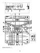
NAMES OF CONTROLS AND INDICATORS For amplifier/tuner (See figure 1 on page 5 at the beginning part of this manual.
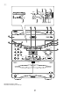
For Tape deck Display (See figure 3 on page 7 at the beginning part of this manual.
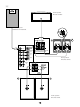
REMOTE CONTROL TRANSMITTER Loading the batteries for the remote control transmitter Proper use of the remote control transmitter (See figure 6 on page 9.) (See figure 7 on page 9.) 1 Remove the battery compartment cover. (Slide the cover in the direction of the arrow.) 2 Aim (within the range of 60° with no obstacles) the remote control transmitter at the remote control sensor and operate as shown. Insert 2 “AA” size batteries (UM/SUM-3, R6, HP-7 or equivalent) into the battery compartment.
This system is designed to provide the best sound-field quality with a 5 speaker configuration: front speakers, rear speakers and a center speaker. You may omit the center speaker, if for some reason it is not practical to use a center speaker. (Refer to the “4Speaker Configuration” shown below.) The front speakers are used for the main source sound plus the effect sounds. The rear speakers are used for the effect and surround sounds, and the center speaker is for the center sounds (dialog etc.).
SETTING UP THE SPEAKERS ■ Mounting the rear speakers 1 Mount the rear speakers on a shelf, rack or on the floor directly, or hang them on the wall. To mount the rear speakers on a wall 1 Attach the provided mounting bracket to the rear of the speaker by using the provided screws. 2 Fasten screws into a firm wall or wall support as shown in the diagram, and hang the holes of the mounting bracket on the protruding screws.
■ Mounting the center speaker Place the speaker on top of the TV or on the floor under the TV or inside the TV rack so that it is stabilized. When placing the speaker on top of the TV, to prevent the speaker from falling down, put the provided pads at four points on bottom of the speaker. Notes • Do not place the speaker on top of the TV whose area is smaller than the bottom area of the speaker. If placed, the speaker may drop out causing an injury to you.
CONNECTIONS Antenna connection (1) (1) Supplied FM antenna ANTENNA FM GND Connect the FM antenna wire to the corresponding terminal and direct the FM antenna wire to the direction where the strongest signal can be received. AM 75Ω UNBAL. (2) Supplied AM (MW/LW) loop antenna Connect the AM (MW/LW) loop antenna wires to the corresponding terminals. Position the AM (MW/LW) loop antenna for optimum reception. Place the AM (MW/LW) loop antenna on a shelf etc.
Connecting external components Connecting the AC supply lead (See figure 9 on page 1 1.) (See figure @ on page 1 2.) This system can be connected with external audio and video components. Make connections between this system and other components using RCA pin plug connector cables correctly, that is to say L (left) to L and R (right) to R. Also, refer to the owner’s manual for each component to be connected to this system.
SETTING THE CLOCK (See figure D on page 1 2.) 1 While the power is on, press the DISPLAY button to display the time. If the power is off, you can proceed to the next step. 2 While holding the TIME ADJ button pressed, press the HOUR button and set the hour. * Press the HOUR button once to advance the time by 1 hour. Press and hold to advance continuously. * To reverse the hour, press the button instead of the HOUR button. 3 Europe, U.K., Australia, China and Singapore models use a 24-hour display. U.S.
This procedure lets you adjust the sound output level balance between the front, center, and rear speakers using the built-in test tone generator. When this adjustment is performed, the sound output level heard at the listening position will be the same from each speaker. This is important for the best performance of the built-in Doiby Pro Logic surround decoder. The adjustment of each speaker output level should be done at your listening position with the remote control transmitter.
SPEAKER BALANCE ADJUSTMENT 6 Adjust the sound output levels of the center speaker and the rear speakers by using the LEVEL control buttons so that they become almost as same as that of the front speakers. ● When the test tone is output from the center speaker, pressing the LEVEL control buttons change the output level of the center speaker. MUSIC 1 2 CD 3 4 1 2 3 4 6 7 8 6 7 8 5 0 A B C D E PROG TAPE EDIT +I0 MODE REPEAT CENTER/REAR /DELAY TEST LEVEL 100 350 1K 3.
CD playback DISC selector buttons 7 2, 4 DISC CHANGE MINI COMPONENT SYSTEM GX–70 OPEN/CLOSE 1 SEEK PTY T 2 DISC STAR 3 /RT/CT PTY Q PS/ FRE PROGRAM PRESET/TUNING/BAND MUSIC RAND MO 4 Press the OPEN/CLOSE button to close the disc table. * The total number of tracks and the total playing time of the disc being selected will be displayed for several seconds. * The music calendar will be displayed only for the number of tracks on the disc being selected.
COMPACT DISC PLAYER OPERATION Direct operation To interrupt playback 1 Press the play/pause / button. * The “ ” indicator will flash. 2 Press the play/pause from the same point. / When the power is off (in the standby mode), pressing the CD input selector button or the DISC selector (1, 2 or 3) button will turn the power on and start CD playback automatically.
“Skip search” and “Manual search” are performed using the same buttons. 2 Skip search The beginning of any track can be found automatically.
COMPACT DISC PLAYER OPERATION Program play 6 1 You can program up to 20 tracks in any desired order. DISC CHANGE MINI COMPONENT SYSTEM GX–70 OPEN/CLOSE 1 SEEK PTY T 2 STAR 3 DISC /RT/CT PTY Q PS/ FRE PROGRAM PRESET/TUNING/BAND MUSIC MO DE DIS If necessary, select a desired disc by pressing the DISC SKIP button. 4 Use the track number input buttons to select the desired track number.
To stop program play / • • DISC CHANGE MINI COMPONENT SYSTEM GX–70 OPEN/CLOSE Press the stop button. The first programmed track number will be displayed. To resume playback, press the play/pause / button. Playback will begin from the beginning of the program. To cancel a programmed sequence 1 SEEK PTY T 2 DISC STAR 3 /RT/CT PTY Q PS/ FRE PROGRAM PRESET/TUNING/BAND MUSIC RAND MO There are several methods as described below. • Press the stop button while the unit is stopped.
COMPACT DISC PLAYER OPERATION 2 Repeat play 1 All discs, an entire disc, a single track or a programmed sequence can be continuously repeated. DISC CHANGE MINI COMPONENT SYSTEM GX–70 OPEN/CLOSE 1 SEEK PTY T 2 DISC STAR 3 /RT/CT PTY Q PS/ FRE PROGRAM PRESET/TUNING/BAND MUSIC RAND MO / button. IT ED DE AT REPE VOLUME Repeat play modes UP UP TAPE 1/2 REC/PAUSE SINGLE REPEAT (S REP) A single track is played back repeatedly.
Random play 3 1 Tracks on a selected disc or all discs on the disc table can be played back in a random order. DISC CHANGE MINI COMPONENT SYSTEM GX–70 OPEN/CLOSE 1 SEEK PTY T 2 STAR 3 DISC /RT/CT PTY Q PS/ FRE PROGRAM PRESET/TUNING/BAND MUSIC MO DE Press the RANDOM button to begin random play. * The “RANDOM” indicator will light up. IT ED VOLUME A/B/C/D/E INPUT 3 AY If necessary, switch the disc play mode by pressing the disc play MODE selector button.
TUNING OPERATION Normally, if station signals are strong and there is no interference, quick automatic-search tuning (Automatic tuning) is possible. However, if signals of the station you want to select are weak, you must tune to it manually (Manual tuning).
English TUNING OPERATION Preset tuning This unit can store station frequencies selected by tuning operation. With this function, you can select any desired station by only calling the corresponding preset station number. Up to 40 stations (8 stations x 5 groups) can be stored.
TUNING OPERATION 1 Automatic preset tuning 2 You can also make use of an automatic preset tuning function. By this function, this unit performs automatic tuning and stores stations with strong signals sequentially. Up to 40 stations are stored automatically in the same way as in the manual preset tuning method on the previous page.
RDS (Radio Data System) is a data transmission system gradually being introduced by FM stations in many countries. Stations using this system transmit an inaudible stream of data in addition to the normal radio signal. RDS data contains various information, such as PI (Program Identification), PS (Program Service name), PTY (Program Type), RT (Radio Text), CT (Clock Time), etc. RDS function is carried out among the network stations.
RECEIVING RDS STATIONS ➀ Changing the RDS modes When an RDS station is received, by pressing the FREQ PS/PTY/RT/CT selector button once or more, you can change the display mode among the RDS modes employed by the received station in the order shown below. (The RDS mode not employed by the station cannot be selected.
● There may be a case that RDS data reception is not possible due to poor reception conditions. If so, press the AUTO/MAN’L button so that “AUTO” goes off from the display. Though the reception mode is changed to monaural by this operation, when you change the display to an RDS mode, RDS data may be displayed. ● If the signal strength gets weakened by external interference during receiving an RDS station, the RDS data service may be cut off suddenly and turn into the frequency display mode.
RECEIVING RDS STATIONS Other functions which make use of RDS data service ➀ ON (OFF) CT > CLOCK This unit corrects the time of the built-in clock automatically by synchronizing it with the CT data on the RDS station being received. * If you receive an RDS station of some other country, the built-in clock is synchronized with the time setting of the country. * If the built-in clock is not yet set for current time or reset due to a power failure etc.
English TAPE DECK OPERATION General information • • • • • • • Detection hole • Tab Do not use C-120 tapes or poor-quality tapes, since they can cause malfunctions. Before loading a tape into the cassette compartment, tighten the tape slack with a pen or pencil. Tapes have removable tabs which prevent accidental recording or erasing from taking place. Removing the tab on the top left protects the side facing you from erasure. Cover the tab holes with adhesive tape to erase or record again.
TAPE DECK OPERATION Tape 1 or tape 2 playback 4 5 1, 3 DISC CHANGE MINI COMPONENT SYSTEM GX–70 OPEN/CLOSE 1 SEEK PTY T 2 DISC STAR 3 /RT/CT PTY Q PS/ FRE PROGRAM PRESET/TUNING/BAND MUSIC RAND MO DIS 3 Load a tape into the deck 1 or deck 2 cassette compartment, and close the lid panel completely by pressing the panel until it clicks.
Notes • When removing the tape, press the stop button, and then open the cassette compartment. • Even if you press the TAPE 1/2 input selector button on the front panel or the TAPE 1/2 button on the remote control transmitter during playback, the playback of currently selected tape cannot be changed to the other one though the tape number indicator on the display changes.
TAPE DECK OPERATION Continuous playback DISC CHANGE MINI COMPONENT SYSTEM GX–70 OPEN/CLOSE 1 SEEK PTY DIS T 2 DISC STAR 3 /RT/CT PTY Q PS/ FRE PROGRAM PRESET/TUNING/BAND MUSIC MO PL The reverse MODE selector button can be operated before or during playback, and changes tape playback as follows: VOLUME UP INPUT DOWN UP TAPE 1/2 REC/PAUSE NORMAL MODE HIGH DOLBY NR POWER If the reverse mode “ ” is not selected, press the reverse MODE selector button to select it.
English RECORDING COMPACT DISCS General information 6 1 • 6 • • DISC CHANGE MINI COMPONENT SYSTEM GX–70 OPEN/CLOSE 1 SEEK PTY T 2 DISC STAR 3 /RT/CT PTY Q PS/ FRE PROGRAM PRESET/TUNING/BAND MUSIC RAND MO DIS VOLUME A/B/C/D/E DOWN MEMORY • UP INPUT DOWN UP TAPE 1/2 REC/PAUSE NORMAL MODE HIGH DOLBY NR POWER AY AT CD INPUT USER PL IT ED DE REPE OM DUBBING PHONES TIMER REC • MEMORY AUTO/MAN’L Active Servo Technology TIMER TIME ADJ HOUR PLAYBACK MIN 2
RECORDING COMPACT DISCS To stop recording temporarily 1 2 / DISC CHANGE MINI COMPONENT SYSTEM GX–70 OPEN/CLOSE 1 SEEK PTY T 2 DISC STAR 3 /RT/CT PTY Q PS/ FRE PROGRAM PRESET/TUNING/BAND MUSIC RAND MO Choose the selection to be recorded next by using the or button, and then press the play/pause / button of the CD player to resume recording (or simply press the track number input button on the remote control transmitter). To stop recording AY Press the stop button of the tape deck.
1 6 Recording CD(s) on both sides of a tape automatically 1 1 Press the CD input selector button and load the disc to be recorded. 2 3 4 Select the disc by pressing the DISC SKIP button. 5 If the reverse mode “ ” is not selected, press the reverse MODE selector button to select it. 6 Press the EDIT button. (“EDIT” appears on the display.) CD playback and recording starts. Recording is carried out on side A and B of the tape continuously.
RECORDING COMPACT DISCS Automatic tape-editing 1 7 1 This convenient feature can be used to program tracks on a disc (or discs) for recording to tape. By only memorizing the tape’s total possible recording time, the unit will automatically program tracks or help you to program tracks so they will fit onto the tape with the least amount of unrecorded space remaining at each end of the tape.
Notes • When this CD player is in the all disc play mode, if the tape’s total possible recording time is longer than the total playing time of the selected disc, tracks on another disc are recorded continuously. In this case, as many as three discs can be recorded automatically. • The CD player’s repeat play mode will be canceled during this recording mode.
RECORDING COMPACT DISCS 1 9 To record programmed tracks from one or more discs 1 1 Press the CD input selector button and load a disc (or discs) on the disc table. 2 3 Follow steps 3–6 on page 38. 4 If necessary, select a desired disc by pressing the DISC SKIP button. 5 Select the desired track number by pressing the track number input buttons. 6 Repeat steps 4 and 5 to program more selections for the side A of the tape. You can select the same track again.
General information • 1 • • DISC CHANGE MINI COMPONENT SYSTEM GX–70 OPEN/CLOSE 1 SEEK PTY T 2 DISC STAR 3 /RT/CT PTY Q PS/ FRE PROGRAM RA PRESET/TUNING/BAND MUSIC MO DIS VOLUME A/B/C/D/E • CD INPUT UP INPUT DOWN UP MEMORY TAPE 1/2 REC/PAUSE NORMAL MODE HIGH DOLBY NR POWER AY AT DOWN USER PL IT ED DE REPE NDOM DUBBING PHONES TIMER REC When recording important selections, be sure to make a preliminary test to ensure that the desired source material is being pr
OTHER RECORDINGS Dubbing • 1 2 • DISC CHANGE MINI COMPONENT SYSTEM GX–70 During dubbing, adjusting the VOLUME control and using the built-in graphic equalizer and the sound field processor have no effect on the recorded sound. Try to use the same tape formula and length for the recording tape as for the master tape.
To listen to or watch a source on an external unit connected with this system 1 Press the INPUT selector or button once or more 1, 1 and select the position of input source (MD/AUX, VCR or LD/TV) you will play back confirming it on the display. * The names of input source positions correspond with the names of terminals to connect with external units on the rear of the main unit.
USING GRAPHIC EQUALIZER The built-in graphic equalizer presents you with the pleasure of listening to music with various sound effects. This system provides 4 preset equalizer modes as listed right. You can enjoy listening to music with a desired sound effect by selecting one of these modes. In addition, the built-in 5 band graphic equalizer allows you to adjust the equalizer pattern to create an effect for your desired sound taste.
Adjusting the graphic equalizer for your desired sound taste 3 The 5 band graphic equalizer allows you to adjust the level for each frequency band. * Make adjustment by monitoring the equalizer level indicators on the display. DISC CHANGE MINI COMPONENT SYSTEM GX–70 OPEN/CLOSE 1 SEEK PTY DIS T 2 DISC STAR 3 /RT/CT PTY Q PS/ FRE PROGRAM PRESET/TUNING/BAND MUSIC RAND MO 2 Press the equalizer control or button once or more to select the frequency band to which you will adjust the level.
USING SOUND FIELD PROCESSOR The Sound Field Processor built into this system presents you with the ambience of an actual concert hall etc. by adding effects as sonic reflections or reberverations that create the sound environment of a hall etc. This system provides preset sound field programs shown below. You can enjoy an excellent audio sound field by selecting one of them, and adding desired adjustments.
Listening to the music with a sound field effect 2 1 Play back a source. (For source playback, refer to the sections beginning on page 17.) 2 Press the PROGRAM button once or more so that the name of a desired program appears on the sound field program indicator. * Whenever you press the PROGRAM button, the program changes and is displayed as follows.
USING SOUND FIELD PROCESSOR Adjusting CENTER LEVEL If desired, you can adjust the sound output level of the center speaker even if the output level is already set in “SPEAKER BALANCE ADJUSTMENT” on page 15–16. 1 2 CD 3 4 1 2 3 4 6 7 8 6 7 8 9 0 A B C D E PROG TAPE EDIT +I0 MODE REPEAT CENTER/REAR /DELAY TEST LEVEL 1 Press the CENTER/REAR/DELAY selector button once or more so that “CENT” appears on the display.
Adjusting DELAY TIME 1 2 CD 3 4 1 2 3 4 6 7 8 6 7 8 5 9 0 A B C D E PROG TAPE EDIT +I0 MODE REPEAT RANDOM OPEN/CLOSE TUNER DISC SKIP 1 5 PRESET TIME REC/PAUSE TAPE 1/2 CENTER/REAR /DELAY TEST LEVEL You can adjust the time difference between the beginning of the source sound and the beginning of the effect sound. This adjustment can be made to all programs (except DOLBY 3 STEREO) individually.
STORING YOUR OWN PROGRAMS 2 1 Your favorite pair of any equalizer mode (or an equalizer pattern of your own adjusting) and any sound field program can be stored as a user program. Up to 4 pairs can be stored as desired. 1 DISC CHANGE MINI COMPONENT SYSTEM GX–70 To store OPEN/CLOSE 1 SEEK PTY T 2 DISC STAR 3 /RT/CT PTY Q PS/ FRE PROGRAM PRESET/TUNING/BAND MUSIC RAND MO Select a desired sound field program by pressing the PROGRAM button. 3 Press the user program MEMORY button.
Singing karaoke This system allows you to enjoy singing karaoke by using not only a source for karaoke use but also any normal audio source. 1 MIC MIC MIXING MIN 1 Connect one or two microphones to the MIC jack(s) on the front panel. 2 Play back a source. (For source playback, refer to the sections beginning on page 17.
HOW TO USE THE BUILT-IN TIMER Timer play By using the built-in timer, you can set the time when the unit turns on and a source begins playing automatically, and the time when the unit turns off automatically. DISC CHANGE MINI COMPONENT SYSTEM GX–70 OPEN/CLOSE 1 Prepare the source to be played. For tuner: Tune in to the station you will listen to.
POWER TIMER DISC CHANGE OPEN/CLOSE 1 SEEK PTY T 2 STAR 3 /RT/CT PTY Q PS/ FRE PROGRAM PRESET/TUNING/BAND MUSIC At OFF TIME/time setting mode [“OFF TIME” appears on the display, and soon it is changed to a time setting mode.] If necessary, set to the time when you want to finish the timer play (to turn this unit off) by using the HOUR button and the MIN button. Even if you do not set the time, it has already been set so that the timer play finishes after 1 hour.
HOW TO USE THE BUILT-IN TIMER 5 POWER Timer recording (To record a tuner program) DISPLAY DISC CHANGE MINI COMPONENT SYSTEM GX–70 OPEN/CLOSE 1 SEEK PTY DIS T 2 DISC STAR 3 /RT/CT PTY Q PS/ FRE PROGRAM PRESET/TUNING/BAND MUSIC RAND MO PL AT VOLUME 3 Tune in to the station of which program you want to record. 4 Follow step 2 of the “Timer play” on page 52 and 53.
English HOW TO USE THE BUILT-IN TIMER Sleep timer operation This unit can be turned off automatically. DISC CHANGE MINI COMPONENT SYSTEM GX–70 OPEN/CLOSE 1 SEEK PTY T 2 STAR 3 /RT/CT PTY Q PS/ FRE PRESET/TUNING/BAND MUSIC RAND MO Press the SLEEP button repeatedly until the desired sleep time appears on the display. The display will change as described below. [Time is displayed by the hour (h) and the minute (m).
MAINTENANCE Internal care Deck 1 • • Deck 2 Dirty heads, capstans and pinch rollers can cause poor sound and tape jams. Clean these parts with a cotton swab moistened with commercially available head/pinch roller cleaner or isopropyl alcohol, or with a commercially available cleaning tape. After long use, the deck’s heads and capstans may become magnetized, causing poor sound. Demagnetize these parts once every 30 hours of playing/recording time by using a commercially available tape head demagnetizer.
CAUSE SYMPTOM Excessive static in FM broadcasts. Interference from starting motor of nearby car. AMPLIFIER/TUNER Interference from thermostat of nearby electrical appliance. REMEDY Position the FM antenna as high and as far away from nearby roads as possible. Connect using a coaxial cable. Noise increases during stereo broadcasts. Antenna input is too weak due to obstructions or excessive distance from broadcasting station. Check antenna connections.
SPECIFICATIONS As a part of policy of continuous improvement, YAMAHA reserves the right to make design and specification changes for product improvement without prior notice. The performance specification figures indicated are nominal values of production units. ■ Amplifier section ■ Tuner section Minimum RMS Output Power per Channel Front L, R 6 ohms, 1 kHz, 1% THD ............................................. 65W+65W 6 ohms, 1 kHz, 10% THD [U.S.A., Canada, China, Singapore and General models only] .....
■ Speaker section ■ General Type Front .................. 3-Way Active Servo Processing Speaker System (Magnetic-Shielding Type) Center ................................................. Full Range Speaker System (Magnetic-Shielding Type) Rear .................................................... Full Range Speaker System Speakers Front.............................................................. 13 cm (5-1/8”) woofer 5 cm (1-15/16”) tweeter 2 cm (13/16”) super tweeter Center...............................
YAMAHA YAMAHA YAMAHA YAMAHA YAMAHA YAMAHA YAMAHA ELECTRONICS CORPORATION, USA 6660 ORANGETHORPE AVE., BUENA PARK, CALIF. 90620, U.S.A. CANADA MUSIC LTD. 135 MILNER AVE., SCARBOROUGH, ONTARIO M1S 3R1, CANADA ELECTRONIK EUROPA G.m.b.H. SIEMENSSTR. 22-34, 25462 RELLINGEN BEI HAMBURG, F.R. OF GERMANY ELECTRONIQUE FRANCE S.A. RUE AMBROISE CROIZAT BP70 CROISSY-BEAUBOURG 77312 MARNE-LA-VALLEE CEDEX02, FRANCE ELECTRONICS (UK) LTD. YAMAHA HOUSE, 200 RICKMANSWORTH ROAD WATFORD, HERTS WD1 7JS, ENGLAND SCANDINAVIA A.