OWNER'S MANUAL
IMPORTANTSAFETYINSTRUCTIONS l0 I_:lltllilfl Ventilation - Slots and openings in the cabinet for ventilation and to ensure refiable operation product HISI( OFELECTRIC SHOCK DONOTOPEN CAUTION: z TO REDUCE THE RISK OF of Graphical l If 2 -All should be read before Retain should Instructions be retained the safety the product and operating 3 Heed Warnings -- All warnings on the product operating instructions should be adhered to. and in the 4 Follow Instructions should be followed.
d) If the product does not operate normally by following the operating instructions.
1 To assure the finest performance, please read this manual carefully. Keep it in a safe place for future reference. 2 Install this sound system in a well ventilated, cool, dry, clean place -- away from direct sunlight, heat sources, vibration, dust, moisture, and/or cold. Allow ventilation space of at least 30 cm on the top, 20 cm on the left and right, and 20 cm on the back of this unit. 3 Locate this unit away from other electrical appliances, motors, humming sounds.
CONTENTS FEATURES ............................................................ ............................................................. 1 2 GETTING STARTED ............................................ Supplied accessories .................................................. Installing batteries in the remote control ................... CONTROLS AND FUNCTIONS ......................... Front panel ................................................................. Remote control ..........................
Built-in 6-channel power amplifier • Minimum RMS oulput power (0.06% THD, 20 Hz - 20 kHz, 8_) Multi-mode digital sound field processing • Dolby Pro Logic/Dolby Pro Logic II decoder • Dolby Digital/Dolby Digital EX decoder • DTS_TS-ES Matrix 6.1, Discrete 6.1, DTS Neo:6 Decoder • CINEMA DSP: Combination of YAMAHA DSP [U.S.A.
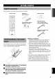
Afterunpacking, check thatthefollowing parts arecontained. Remote control DD[] Batteries (4) (AAA, R03, UM-4) AM loop antenna 75*ohm/300*ohm antenna (U.S.A., Canada, China, Korea and General models) Indoor FM antenna adapter (U.K. model) (Europe, U.K., Australia and Singapore models) ®l V • Insert the batteries in the correct direction by aligning the + and - marks on the batteries with the polarity markings (+ and -) inside the battery compartment.
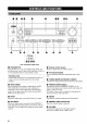
© I I (U.K. and Europe models only) O STANDBY/ON Turns the unit on, or sets it in standby mode. When you turn lhe unit on, you will hear a click and there will be a 4 to 5-second delay before it can reproduce sound. Standby mode In this mode, the unit uses a small amount of power order to receive infrared-signals from the remote control. Remote control sensor Receives signals from the remote control. Front Shows unit.
_!ShTIE:lollT_lV'_|A_ltaJgllh_[_ll[Oh_ _1 _ SILENT (PHONES jack) Allows you to enjoy DSP effects when lislening with headphones. When you connect headphones to the headphone jack, no signals are oulput m the speakers. _) SPEAKERS A/B Turns the set of main speakers B terminals on or off. _) STEREO/EFFECT Switches between noianal connected stereo to the A and/or and DSP effect and/or frequency PTY SEEK MODE Press this button to set the unit in the H'Y mode.
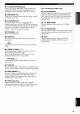
[t[l]k_ll:{#]l.'f__Tk_lll._lh_[l_l[O]LT[ This section describes their functions. Make before starting the remote conlrol conlrols and sure thai the AMP mode is selected operation. O pOWI_R Infrared window Outputs infrared conlrol signals. component you want to operate. 0 r DD 0 CODE Input selector codes (see page 46). buttons Select lhe input source and set lhe remote operate the selecled source component.
qShTIE:lollk_lV'_|A_ltaJg;llh_[Olll[Oh_ @ MUTE • Mutes the sound. Press again to restore to the previous volume level. O the audio Using the remote control output 6.1/5.1 Switches off. the Dolby Digital EX or DTS ES decoder _) STEREO/EFFECT Switches between no,Trial stereo on or and DSP effect Approximately 6 m (20 feet) reproduction.
[t[l]k_ll:{#]l.'f'_Tk_lll._lJi_[l_l[O]LT[ f--_R V-AUX HiFi D_TV/CBL OVD MD/CD_ TUNER DSP (U.K. and Europe models only) 0 Processor indicators The indicators for the various decoders are in use. 1_ decoders light up when the O VIRTUAL indicator Lights up when using Virtual CINEMA DSR Headphones indicator Lights up when headphones are connecled to the headphone jack. AUTO indicator Shows thai this unit is in the automatic tuning mode. MUTE indicator Flashes while the MUTE funcfion is on.
Do not connect this unit or other components to the mains power until all connections between the components have been completed. • Be sure all connections are made correctly, that is to say L (left) m L, R (righl) to R, "+" to "+" and "-" to "-', Some components require different connection methods and have different jack names. Refer m the operation instructions for each component you wish to connect to this unit.
• Connecting a video monitor Connect the video input jack on your video monitor to the MONITOR OUT VIDEO jack. Refer to the connection examples on the next page. • Types of video jacks • If you connect this unit with a source component Component video jacks, you also need to connect monitor using Component using your video video jacks.
-pl_l_Hff'ttol_= OPTICAL OUTPUT I 9 AUDIO DVD player OUTPUT I I _ )PTICAL )UTPUT _ AUDIO _OUTPUT I TV/digital TV/ cable TV VIDEO OUTPUT OUTPUT VIDEO J iiii;ii!!_!;!ii!i!!i_!iiii!i!i_iiiii!iiiiiii!_!ii!iii_i_ au 2_ N;_.... ILL°.,ZoZ_,f ............................. _ .....
• Use the AUDIO jacks on this unit lbr a CD recorder or MD recorder which does not have optical digital inp_t or output • Connecting a CD player jack. Connect lhe coaxial digital output jack on your CD player to the DIGITAL INPUT CD jack on this unit. .%,. • Once • Use the AUD10 jacks on this unit for a CD player which does not have coaxial digital output jack.
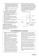
Both AM and FM indoor unit. In general, signal strength. antennas these antennas Connect each antenna terminals. are included should correctly provide with this • Connecting the AM loop antenna sufficient [] Set up the AM loop antenna, then connect it to the terminals on this unit. [] Press and hold the tab to insert the AM loop antenna lead wires into the AM ANT and GND terminals, [] Orient the AM loop antenna for the best reception.
This unit is equipped with 6 additional input jacks (MAIN lefl and right, CENTER, SURROUND lefl and right and SUBWOOFER) for discrele multi-channel input from a component equipped with a multi=channel decoder and 6 channel output jacks such as a DVD/SACD player. CENTER MAIN SUBWOOFER DVD/SACD player • When you select 6CH INPUT as the input source, the unit automatically turns off the digital sound field processor, and you cannot 14 use DSP programs.
• Speaker placement Refer to the following diagram when you place the speakers. • Speakers This unit has been designed Io provide the best sound= field quality with a 6=speaker system, using main left and right speakers, rear left and right speakers, a center speaker, and a rear center speaker. If you use different brands of speakers (with different tonal qualities) in your system, the tone of a moving human voice and other types of sound may not shift smoothly.
• Connections Be sure to connect 1he lefl channel (L), right channel (R), "+" (red) and "-" (black) in accordance with the markers on this unit, the speakers, and the speaker cables. If the connections are faulty, no sound will be heard from the speakers, and if the polarity of 1he speaker connections is incorrect, the sound will be unnatural and lack bass.
Main A speaker Right Rear speaker Left Right o SPEAKERS 0 Center Subwoofer system MAIN Left Right Left Main B speaker speaker Rear center speaker terminals You can connect up to two speaker syslems to these lerminals. When using only one speaker system, connect it to either of 1he MAIN A or the MAIN B terminals. REAR SPEAKERS A rear speaker terminals. system terminals can be connected to these \\ \ CENTER SPEAKER terminals A center speaker can be connected to these terminals.
When all connections are complete, turn on the power of this unit. VOLTAGE SELECTOR -1 (General model) • Connecting the AC power Plug in this unit to a wall outlet. cord • AC OUTLETS (SWITCHED) U.S.A, Canada, China, Europe, Singapore and General models .............................................. 2 OUTLETS U.K. and Australia model ................................ 1 OUTLET Use these outlets to connect the power cords from your components to this unit.
The "BASIC" menu allows you to set some of the basic "SOUND" menu paramelers with a minimum of effort. If you wish to configure the unit more precisely to suit your listening environment, use the more detailed paramelers from the "SOUND" menu instead of those under the "BASIC" menu (See page 39). Altering any parameters in the BASIC menu will reset all paramelers in 1he "SOUND" menu. [] Press A / v to change the display to the setting you want to alter. SETUP Use the remote control to make adjustments.
INPUT BASICMENU SOUND SET I 1 .+ SETUP Press < / > to aller parameler. Use v the settings to move for each to the next setting. I OPTION 2 SP LEVEL Press ( / > to adjust the balance between each speaker. Use speaker v and to move the left to the main next setting. @ ROOM I Choose ] Adjust the balance from S/M/L. @L-R left and right between @C @ SUBWOOFER Adjust the balance between Choose left and center e t ler of YES/NONE. Adjust tile balance from 2/3/4/5/6 spk.
SET or CANCEL Follow lhe inslructions below to set the amplifier output Io malch the size of your room and speakers. Press A / v m cycle through parameters 1 through 4, and ( / > to alter the parameler setting. Factory default settings are highlighted. Select SET to confirm the changes you made to the above three settings. The unit will output a lest tone to the speakers (see ®). Alternatively, select CANCEL Io exit this menu without altering any of the unit settings.
1 44 6 [] Rotate the INPUT selector (or press one of the input selector buttons on the remote control) to select the input source. The selected input source name and input mode appear on the front panel display for a few seconds. ° or 3 7 6 Front panel dlbm Yen Remote control v_x _TV/C_ _ a_/cOa TOUR COV_ ........
'./IIV., | _ _y.* T_/ [] Start playback or select a broadcast station on the source component. Refer to the operation inslructions for the component. [] Adjust the volume to the desired level. The volume level is displayed digitally. Example: -70 dB Control range: VOLUME MUTE (minimum) to 0 dB (maximum) The volume level indicalor also shows the current volume • BGV (background video) function The BGV function allows you to view images from a video source together with sounds from an audio source.
I_lF.,|_l_r.,Tol' This unit is equipped with a variety of input jacks. You can select the type of input signals you wish to use. Each time you turn on the unit power, 1he input mode is set to lhe "INPUT 2 INPUT MODE" setting defined in the set menu. Press INPUT MODE repeatedly until the desired input mode is shown on the front panel display. INPUT MODE Front panel W_ V.AL_ _V_eL TtJNEA CD VDLUM_ ........ [)i.j[) ,,,11111 I..i I DVD _DJCD_ .....
[] You can enhance your listening experience by selecting a DSP program. For details about each program, see pages 28 - 30. After selecting the desired the same button repeatedly sub-programs Example: PROGRAM <_ / _> program, press to cycle through if available. Pressing MOVIE THEATER 2 repealedly swilches the sub-program between "Adventure" and "General". wR T_n co _c_ .,1111111 (_,i? n ,i? ._" a i -1 _@ • There are 9 programs with sub-pJograms available with this unit.
rdlg.,|_l_r.,y_/, • Selecting PRO LOGIC, PRO LOGIC II or Neo:6 You can listen to 2-channel sources decoded into five or six discrete channels by selecting PRO LOGIC, LOGIC lI or Neo:6 in program No. 9. PRO The display cycles as follows each time you press rlD/ DTS SUR : PRO LOGIC--)PRO LOGIC Enhanced-_PRO LOGIC II Movie-_PRO LOGIC II Music--_Neo:6 Cinema--_Neo:6 Music--_PRO LOGIC--) ....
'JIg.,| It_Y.* T_/ • Virtual CINEMA DSP With Virtual CINEMA DSP, you can enjoy all DSP programs without rear speakers. It creates virtual speakers to reproduce a natural sound field. You can listen to virtual CINEMA DSP by setting "IC REAR LR" in the set menu to NON. Sound field processing changes to VIRTUAL CINEMA DSP automatically.
A sound field is defined as lhe "characleristic sound reflections of a particular space:' In concert halls and other music venues, we hear early reflections and reverberations as well as the direct sound produced by the arlist(s). The variations in the early reflections and other reverberations among the different music venues is what gives each venue its special and recognizable sound quality.
Filmmakers intend for the dialog to be located right on the screen, the effect sound a little farther back, the music spread even farlher back, and the surround sound around the listener. Of course, all of these sounds must be synchronized with the images on the screen. CINEMA-DSP is an upgraded version of YAMAHA DSP specially designed for movie soundtracks.
• For movie programs No. 7 Program MOVIE Features Spectacle THEATER "]['his program 1 precisely incredibly Dolby Sci-Fi This creates the extremely reproduces the source real. This is ideal Digital or DTS program clearly fiction silence. You can enjoy Doiby films, Surround, (especially dialog science Digital of a 70-mm making movie movie theater. both the video source encoded It and the sound with Dolby field Surround, productions).
q/,_/_lri¢.,U )/.*./ The 6-channel soundtracks found on 70-mm film produce precise sound field localization and rich, deep sound without using matrix processing. This unit's MOVIE THEATER programs provide the same quality of sound and sound localization that 6-channel soundlracks do. The built-in Dolby Digital or DTS decoder brings the professional-quality sound designed for movie theaters into your home.
There are 2 methods of tuning; automatic and manual. Automatic tuning is effective when station signals are strong and there is no interference. [] • Automatic tuning 1 Press PRESET/TUNING <_/I> once to begin automatic tuning. Press 1:::> to tune in to a higher frequency, or press <:3 to tune in to a lower frequency.
PIN_; • Automatically presetting stations (for FM stations) You can use the automatic FM stations. This function preset tuning feature enables the unit to Any stored • cleared when If the number to store automatic searching automatically tune in to FM stations with strong signals, and to store up to 40 (8 stations x 5 groups) of those stations in order. You can then recall any preset station easily by selecting the preset number. 2 • • Only station preset tuning all stations.
Sl#l_llt[I • Manually presetting stations You can store up to 40 stations (8 stations x 5 groups) manually. [] 2,5 Press PRESET/TUNING <_ / I> to select a preset station number (1 to 8) while the "MEMORY" indicator is flashing. Press 1::>to select a higher preset station ]lumber. Press <3 to select a lower preset station number. ve_ VAbX _W/CeL DVO _DJ:_ _nv _ 3 4 Preset number [] Tune in to a station. [] See page 32 for tuning instructions. v_R VAUX _W/r_t orb _ nJNER !:? !:.
You can recall any desired station simply by selecting preset station number under which it was stored. the • Exchanging preset stations You can exchange the assignment of two preset stations. The example below describes the procedure for exchanging preset station "El" with "A5". 2,4 1,31,3 [] Select preset station "El" by using the A/B/C/D/E and PRESET/TUNING <_ / _>.
Use this feature to automatically set this unit in standby mode after the amount of time you have set. The sleep timer is useful when you are going to sleep while this unit is playing or recording a source. The sleep timer also automatically turns off the external component(s) connected to AC OUTLET(S). The sleep timer can only be set with the remote SLEEP • By connecting a commemially available timer to this unit, you can also set a wake-up timer. Refer to the operation instructions of the timer.
Recording adjustments and other operations are performed on other recording components. Refer to the operation instructions for these components for details on their operation. • Do a test recording befoie you start an actual recording. • When this unit is set in standby mode, you camlot iecord between the components connected to it. • DSP programs and volume, bass, and treble settings do not affected the lecolded material. • You cannot record from a source connected to the 6CH 1NPUT jacks on this unit.
You can set the following paramelers on the set menu to obtain a better sound from the unit. Change the settings to reflect the needs of your lislening environment. Use the remote The set menus are divided categories listed here. by use and function control to make adjustments. into the 4 • BASIC The BASIC area contains the basic parameters that you must set before using this unit. It consists of the following menus. See pages 19 - 21 for a detailed explanation.
[] Press { / ) once to enter the setup mode of the selected item. The last setting you adjusted appears on the front panel display. Use this feature to select suitable oulput modes for your speaker configuration. Depending on the menu ilem, press/x/v to select a sub item. • Some menu item settings have no effect when the unit _s reproducing a source with a digital signal sampling frequency greater than 48 kHz. [] Press { / ) repeatedly to change the menu item setting.
• 1B MAIN (main speaker Choices: LARGE, SMALL mode) LARGE Select this if you have large main speakers. The unit directs the entire range of the main left and right channel signals to the main left and right speakers. • 1D REAR CT (rear center speaker mode) If you add a rear center speaker to your speaker configuration, this unit can provide more realistic front= to-back Iransitions. Choices: LRG (large), SML (small), NON (none) LRG SMALL Select this if you have small main speakers.
fxlm_l::lg2 Use this feature to adjust 1he output Use this feature to adjust the delay applied to cenler and rear center channel sounds. This feature works when there is sound output from the center speakers with a source such as Dolby Digital or DTS. Ideally, the center speaker and the rear speakers should be the same distance from the main listening position as 1he left and right main speakers.
Use this feature to adjust lhe built-in 5-band graphic equalizer so that the cenler speaker tonal quality matches that oflhe left and right main speakers. You can select the 100 Hz, 300 Hz, 1 kHz, 3 kHz, or 10 kHz frequencies. Conlrol range (dB): _5 to +6 Initial setting: 0 dB for 5-band [] Press v to select a higher frequency and/x to select a lower frequency. [] Press ( / ;' to adjust the level of that frequency.
Use this fealure to designale the input mode for sources connected to the DIGITAL INPUT jacks when you turn this unit on (see page 24 for details about the input mode). Use this feature to prevent accidental changes to settings on the unit. Choices: Select ON lo wotect the following • All set menu items AUTO, Choices: ON, OFF LAST AUTO Select this setting to allow the unit to automatically delect the type of input signal and select lhe appropriate input mode.
• SP B (speaker B set) Use this feature to select the location of the main speakers connected to the SPEAKERS B terminals. Choices: MAIN, ZONE B MAIN Select this to turn on/off SPEAKERS speakers connected in the main room. ZONE to the SPEAKERS A and B when 1he B terminals are set B Select this if the speakers connected to the SPEAKERS B terminals are set another room.
In addition to controlling this unit, the remote control can operate other A/V components made by YAMAHA and other manufacturers. "lb control other components, set up the remote control with the appropriate manufacturer codes. • Controlling this unit The shaded areas below can be used to control this unit when the AMP mode is selected. Press AMP to select the AMP mode.
You can control other components by setting a manufacturer code. Codes can be set for each of the 9 component controls. The following table shows factory-set component (Library: component category) and the manufacturer code for each component control.
You can operale other components if you have set the manufacturer code for your component in lhe remole conlrol. Note, however, that some buttons may not operate the component correctly. Once you select an input source, lhe remole control switches to the mode for operating the component.
You can adjust the volume to sound playback. of the speakers while listening Use the test tone to set speaker levels so that the volume from each speaker is identical when heard from your listening position. -1 -1 _ 3 [] [] Press AMP. [] Press LEVEL repeatedly to select the [] Press AMP. Press TEST. The unit will output a test tone. speaker you want to adjust. The unit cycles through 1he speakers order each time you press MAIN L--_CENTER-->MAIN [] in the following LEVEL: R--_R SUR.
[] The initial sound field program settings will provide you an excellent listening experience as they are_ It is not necessary to aller these settings, but you can create an original listening environment by doing so. • Repeat steps 2 - 4 if you wish to alter other parameters. You cannot GUARD" setting alter these parameter parametel's if the "OPTION in the set menu to OFF if you wish to alter 2 MEM. is set to ON, Change this any other parameters.
You can adjust the values of certain digital sound field parameters so the sound listening room. Not all of 1he following parameters are found in every program. fields are recreated accurately in your • DSP LEVEL Function: This parameler adjusts the level of all the DSP effect sounds within a narrow range. Descriplion: Depending on lhe acoustics of your listening room, you may want to increase or decrease 1he DSP effect level relative to the direct sound.
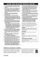
Refer to the chart below when this unit does not function properly. If the problem you are experiencing is not listed below or if the instruction below does not help, set this unit to standby mode, disconnect the power cord, and contact nearest authorized YAMAHA dealer or service center.
Problem Cause Referto Remedy page Only the speaker on one side can be heard. Incorrect No sound from the effect speakers. Tile sound ef!i_ct is switched cable connections. Connect tile cables properly. lhe cables may be defective. oft_ Press STEREO/EFFECT A Dolby Surround, Dolby Digital or DTS decoding DSP program is being used with material not encoded with Dolby Surround, Dolby Digital or DTS. Select another If tile problem persists, 16 to turn it on. 25 - 30 DSP program.
I'.'lol#l_la,_'tMoloJIIA_I Problem Cause Refer Remedy page No sound from the rear center speaken A "humming" be heard. sound can Select LRG or SML. The Dolby Digital EX or ihe DTS-ES decoder is not switched on. Press 6.1/5.1 on the remote control decoder on. Incorrect Firmly conn_i lhe audio plugs. If the problem persists, the cables may be defective. cable conllectJons. The volume level cannot be increased, or the sound is distorted.
• Tuner Problem Cause FM stereo reception is noisy. Tile characteristics Remedy of FM stereo Check the antenna conn_tions. broadcasts may cause this problem when the transmitter is too far away or tile anlenna input is poor. Try using a high-quality antenna. Use tile manual FM There is distortion, and clear reception cannot be obtained even with a There is multipath Refer to page interference. 13 directional FM tuning me_hod. Adjust the antenna position multipath inteffelence.
• Dolby Surround Dolby Surround uses a 4 channel analog recording syslem Io reproduce realistic and dynamic sound effects: 2 main left and right channels (stereo), a cenler channel for dialog (monaural), and a rear channel for special sound effects (monaural). The rear channel reproduces sound within a narrow frequency range. Dolby Sm'round is widely used with nearly all video tapes and laser discs, and in many TV and cable broadcasts as well.
[_ Igo/¢'N"Y;T_t • Virtual CINEMA DSP YAMAHA has developed a virtual CINEMA DSP algorithm that allows you to enjoy DSP sound field surround effects even without any rear speakers by using virtual rear speakers. It is even possible to enjoy virtual CINEMA DSP using a minimal 2-speaker system that does not include a center speaker.
AUDIO SECTION FM • Minimum RMS Output Power tbr Main, Center, Rear, Rear Center [U.S.A. and Canada models] to 20 kttz, 0.06% THD, 8 _') ....................................... 80 W 0.7% THD, 8 g2 .......................................................... 95 W [O_her modelsj to 20 kttz, 0.06% THD, 8 _') ....................................... 70 W 0.7% THD, 8 _2 .......................................................... 85 W • Tuning Range [U.S.A. and Canada models] ............................ 87.
LIST OF MANUFACTURER TV A TANDY 0941 CODES DAYTRON B941, 1031 JBL 010! DECCA 0271, 1001 JCB 0951 JENSEN 031 ! HNXING 1531, 1541, 1551, 1561, 1571, 162!, 1651, DIXI (!331, 1001, ABEX 1151 DUMONT 0891, 1031 ADMIRA 1141 DYNATECH 0881 ADVENTURA 1131 ELECTROBAND 095 I, I (111 1631, 1641, A1KO 1121 ELECTROHOME 0941 169!, 1731 0261, 0281, 0651, 0661, A1WA 1481 AKAI 0331, ALBA 0431 ALLERON 1101, I 1091 AMBASSADOR 1(101 ELTA (!331 EMERSON 0001, ANAM
SAMSI.
HARMAN/KARDON HARWOOD PROSCAN 0632, 1082 0752, 0852 HEADQUARTER 1(102, 1012, 1022, YAMAHA 0202,0632 CARVER 0285, 1(132, 1042, 1052, ZENITH 0042,0362,0512, CASIO 0345 0672 CROWN 1062 0612 PULSAR (1512 (!842 QUARTER (}612 HINARI (1852 QUARTZ (1272, (1612 HITACHI 0102,0562,0572, (1582, ITT JVC (V1CTOR) KENWOOD 0592, QUASAR 0602, DVD 0382,0392,0932 RADIO SHACK 0185 CURTIS HI-Q 0912, 0992 PLAYER MATHES DENON DEUAL AKA1 0058 AIWA 0218 (E) DYNAMIC 0345 0275,
SANYO 0145, 0555, B635, OPTIMUS 0765 SC(YrT 1H25, SEARS 1H45 SHARP (1235, 0665, 1065, 1075 SHERWOOD SIEMENTS 1105 ONKYO PHILIPS 0895, REVOX 0115,0235,0395, SANSUI (1475 SHARP GARRARD SIGNATURE SHERWOOD 1245 SONY (1175 TEAC SONTEC I 165 SONY PIONEER (1065, TECHNICS 0565, 0865, I 145 STARON YAMAHA 1235 STS 0025 SYLVANIA 0215 SYMPHONIC 1H35 TANDY 0305 TANGBERG WARDS 0034, 0/)64, 0334 0364, 0374 0094 0034, eli44, 0354 0094, 0344 0264 0334 0054, 0{t84, 0194,0254 0
OYAMAHA YAMAHA YAMAHA YAMAHA YAMAHA ELECTRONICS CORPORATION, USA 6_60 ORANGETHORPE AVE BUENA PARK CAL]K 90620, USA CAt_ADA MUSIC LTD. _35 MILNER AVE SCARBOROUGH_ ONTARIO M_S 3R1_ CANADA ELECTRON]K EUROPA G.m.b.EI. $]EMENSSTR 2_34 25462 RELLINGEN BE_ HAMBURG¸ _R OF GERMANY ELECTRON]QU£ FRAt_CE _A. RUE AMBROISE CROIZAT BPT0 CRO_SSYBEAUBOURG 773_2 MARNEkLA VALLEE YAMAHA YAMAHA ELECTRONICS SCAt_DINAV[A YAMAHA MUSIC (UIO LT_ YAMAHA HOUSE, 200 R_CKMANSWORTH A.B.