A HTR-6230 AV Receiver OWNER’S MANUAL
Caution: Read this before operating your unit. 1 To assure the finest performance, please read this manual carefully. Keep it in a safe place for future reference. 2 Install this sound system in a well ventilated, cool, dry, clean place – away from direct sunlight, heat sources, vibration, dust, moisture, and/or cold. Allow ventilation space of at least 30 cm on the top, 20 cm on the left and right, and 20 cm on the back of this unit.
Contents INTRODUCTION ADVANCED OPERATION Set menu ................................................................ 30 Supplied accessories .................................................. 2 Using set menu......................................................... 31 1 SOUND MENU.................................................... 31 2 INPUT MENU...................................................... 33 3 OPTION MENU ................................................... 34 Functional overview...............
INTRODUCTION Features Built-in 5-channel power amplifier (1 kHz, 0.
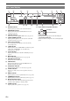
Functional overview Front panel C D E F G H T I P VOLUME INTRODUCTION U OPTIMIZER MIC EDIT PRESET/TUNING l A/B/C/D/E PRESET/TUNING h BAND MEMORY PREPARATION SPEAKERS TUNING AUTO/MAN'L SCENE 1 PHONES TONE CONTROL PROGRAM l STANDBY /ON 2 l EFFECT VIDEO B K L STANDBY/ON M C SPEAKERS D EDIT PRESET/TUNING E A/B/C/D/E Switches the tuning mode (see page 28). Selects the preset station group (A to E) (see page 29).
Functional overview Front panel display a b c d DVR t VIRTUAL ENHANCER e V-AUX DTV/CBL f g MD/CD-R DVD TUNER h CD YPAO AUTO TUNED STEREO MEMORY PRESET SLEEP MUTE SP SILENT CINEMA NIGHT AB q DIGITAL q PL ft q PL mS dB PCM j a k l m Decoder indicator Lights up when any of the decoders of this unit functions. b c ENHANCER indicator SILENT CINEMA indicator Input source indicators YPAO indicator Tuner indicators Lights up when this unit is in the FM or AM tuning mode (see page 28).
Functional overview Remote control AMP i SCENE 1/2/3/4 Press this button before you control this unit (see page 18). c b POWER POWER TV AV A B STANDBY POWER C MUTE d Recalls an input source and a sound field program assigned to each SCENE button (see page 22). j BAND LEVEL TITLE k MENU l Cursors (l/h/n/k) / ENTER Selects the speaker that you want to adjust (see page 20). e CD MD/CD-R TUNER INTRODUCTION h a Displays the set menu on the front panel display (see page 31).
Functional overview Rear panel a b c d e ANTENNA OUT DTV/CBL DVR CENTER FRONT B HDMI COMPONENT VIDEO DVD SPEAKERS SURROUND DTV/CBL DVD MONITOR OUT AM PR GND DIGITAL INPUT VIDEO PB DVD DTV/CBL DVR IN OUT MONITOR OUT FM UNBAL.
Quick start guide The following steps describe the easiest way to operate this unit. See the related pages for details on the operation and settings. Step 3: Connect your components In these steps, you need the following items which are not included in the package of this unit. ❏ Speakers We recommend magnetically shielded speakers. ❏ Center speaker ................................... x 1 ❏ Surround speaker .............................. x 2 ❏ Active subwoofer ...................................
PREPARATION Preparation of remote control Installing batteries in the remote control 1 3 Using the remote control The remote control transmits a directional infrared ray. Be sure to aim the remote control directly at the remote control sensor on this unit during operation. 2 30º 1 Take off the battery compartment cover. 2 Insert the four supplied batteries (AAA, R03, UM-4) according to the polarity markings (+ and –) on the inside of the battery compartment.
Connections Placing speakers Connecting speakers FL C FR SL SR 60˚ SL 80˚ SR 5.1-channel speaker connection c d ANTENNA D f e g ADVANCED OPERATION Center speaker (C) The center speaker is for the center channel sounds (dialog, vocals, etc.). If for some reason it is not practical to use a center speaker, you can do without it. Best results, however, are obtained with the full system.
Connections Speakers Jacks on this unit a Front speaker (A) Right* FRONT A (R) b Front speaker (A) Left* FRONT A (L) c Surround speaker Right SURROUND (R) d Surround speaker Left SURROUND (L) e Center speaker CENTER f Front speaker (B) Right* FRONT B (R) g Front speaker (B) Left* FRONT B (L) h Subwoofer SUBWOOFER * You can select the front speaker set from Front speakers (A) and Front speakers (B) by pressing CSPEAKERS repeatedly. See page 19 for details.
Connections VIDEO jacks For conventional composite video signals transmitted via composite video cables. Connecting video components Audio jacks and cable plugs AUDIO R L DIGITAL AUDIO DIGITAL AUDIO COAXIAL OPTICAL COMPONENT VIDEO jacks For component signals, separated into the luminance (Y) and chrominance (PB, PR) video signals transmitted on separate wires of component video cables.
Connections Connecting a TV monitor or projector Make sure that this unit and other components are unplugged from the AC wall outlets. Note • If you turn off the video monitor connected to the HDMI OUT jack via a DVI connection, the connection may fail. In this case, the HDMI indicator flashes irregularly.
Connections Connecting other components This unit has three types of audio jacks, two types of video jacks and HDMI jacks. You can choose the connection method depending on the component to be connected. ■ Connecting example (connecting a DVD player) PREPARATION ANTENNA OUT DVD SU R DTV/CBL HDMI DVD COMPONENT VIDEO DTV/CBL DVR MONITOR OUT AM PR GND VIDEO DIGITAL INPUT PB DVD DVR DTV/CBL MONITOR OUT OUT IN FM 75 UNBAL.
Connections Component Signal type DVD recorder CD player MD or CD recorder Jacks on component Jacks on this unit Video HDMI out* HDMI (DVR)* Video out (composite) VIDEO (DVR IN) Audio Audio out (analog)* AUDIO (IN (PLAY))* Audio recording Audio in (analog)* AUDIO (OUT (REC))* Video recording Video in (composite)* VIDEO (DVR OUT)* Audio Coaxial out* OPTICAL (CD)* Audio out (analog) AUDIO (CD) Audio Audio out (analog)* AUDIO (IN (PLAY))* Audio recording Audio in (analog)* AUDIO
Connections Connecting the FM and AM antennas Once all connections are complete, plug the power cable into the AC wall outlet. Power cable Notes Outdoor AM antenna L AM loop antenna (supplied) Use a 5 to 10 m (16 to 32 ft) of vinyl-covered wire extended outdoors from a window. PREPARATION • The AM loop antenna should be placed away from this unit. • A properly installed outdoor antenna provides clearer reception than an indoor one.
Optimizing the speaker setting for your listening room (YPAO) This unit has the Yamaha Parametric Acoustic Optimizer (YPAO). With the YPAO, this unit automatically adjusts output characteristics of your speakers based on speaker positions, speaker performances, and acoustic characteristics of the room. We recommend that you first adjust the output characteristics with the YPAO when you use this unit. Caution • Be advised that it is normal for loud test tones to be output during the “AUTO SETUP” procedure.
Optimizing the speaker setting for your listening room (YPAO) Notes 6 When all measurements are completed successfully, “FINISH” appears on the front panel display. The result of the automatic setup for each speaker appears in order on the front panel display. FL: 3.3m +2 The result of the adjustment of the volume level y • To display the result of the automatic setup again, press lk / n repeatedly. Notes Press ll / h to select “SET” or “CANCEL.” Choice EXIT Exits from the “AUTO SETUP” procedure.
BASIC OPERATION Playback Caution Extreme caution should be exercised when you play back CDs encoded in DTS. If you play back a CD encoded in DTS on a DTS-incompatible CD player, you will only hear some unwanted noise that may damage your speakers. Check whether your CD player supports CDs encoded in DTS. Also, check the sound output level of your CD player before you play back a CD encoded in DTS. 5 Rotate PVOLUME (or press mVOLUME +/–) to adjust the volume to the desired output level.
Playback ■ Guide to contents When you want... See page 20 Edit parameters of sound field programs 27 Enjoy the sources which have wide dynamic range at night 20 Use headphones 20 Select a decoder to play back sources with 27 Set this unit to the standby mode automatically 21 y Use the following features to select input jack or input source.
Playback y Using audio features • Once you press jBAND LEVEL TITLE on the remote control, you can also select the speaker by pressing lk / n. • The available speaker channels differ depending on the speaker settings. Use the following features to adjust the audio output or speaker level. ■ 2 Muting the audio output Press eMUTE on the remote control to mute the audio output. Press eMUTE again to resume the audio output.
Playback 2 Choice Function MIN Slightly lowers the effect level. MID* Moderately lowers the effect level. MAX Considerably lowers the effect level. ■ Using the sleep timer Use this feature to automatically set this unit to the standby mode after a certain amount of time. The sleep timer is useful when you are going to sleep while this unit is playing or recording from a source. Press hAMP and then press xSLEEP repeatedly to set the amount of time. The sleep timer setting changes as follows.
Selecting the SCENE templates Just by pressing one SCENE button, you can recall your favorite input source and sound field program according to the SCENE template that has been assigned to the SCENE button. The SCENE templates are built combinations of input sources and sound field programs. This unit is equipped with 12 preset SCENE templates for various situations. The following SCENE templates are assigned to respective SCENE buttons in the default settings.
Selecting the SCENE templates Which SCENE template would you like to select? ■ Video sources (DVD video, Recorded video) SCENE template DVD Viewing DVD STRAIGHT Select this SCENE template when you play back general contents on your DVD player. DVD Movie Viewing DVD Movie Dramatic Select this SCENE template when you play back movies on your DVD player.
Selecting the SCENE templates 2 Creating your original SCENE templates You can create your original SCENE templates for each SCENE button. Refer to the preset 12 SCENE templates to create the original SCENE templates. Customizing the preset SCENE templates • The input source component • The active sound field programs or STRAIGHT mode • The night listening mode setting (see page 20) – SYSTEM: Keeps the current night listening mode. – CINEMA: Sets the night listening mode to the CINEMA mode.
Selecting the SCENE templates Using remote control on the SCENE feature INTRODUCTION Controlling the input source components in the SCENE mode You can operate both this unit and the input source component by using the remote control. You must set the appropriate remote control code for each input source in advance (see page 38). Press the desired iSCENE button on the remote control. 2 Press the desired buttons in the * area below to control the input source component of the selected SCENE template.
Sound field programs This unit is equipped with a variety of precise digital decoders that allow you to enjoy multi-channel playback from almost any stereo or multi-channel sound source. This unit is also equipped with a Yamaha digital sound field processing (DSP) chip containing several sound field programs which you can use to enhance your playback experience. Selecting sound field programs Press LPROGRAM l / h (or press hAMP and then press qPROG l / h repeatedly).
Sound field programs ■ Press hAMP and then press sSUR. DECODE repeatedly to select a decoder. You can select from the following decoders depending on the type of source you are playing and your personal preference.
FM/AM tuning 4 Overview You can use two tuning modes to tune into a desired FM/ AM station: ■ Frequency tuning mode You can search or specify the frequency of the desired FM/AM station automatically or manually (see “FM/AM tuning operations” on this page). To begin automatic tuning, press FPRESET/TUNING l / h once. To tune into the desired station manually, press FPRESET/TUNING l / h repeatedly.
FM/AM tuning y • You can select the preset station group and the preset station number where the first received station will be stored by pressing EA/B/C/D/E and then FPRESET/TUNING l / h. 2 Press FPRESET/TUNING l / h (or lk / n) to select the desired preset station number (1 to 8). The preset station group and number, along with station band and frequency, appear on the front panel display.
ADVANCED OPERATION Set menu You can use the following parameters in the set menu to adjust a variety of system settings and customize the way this unit operates. Change the initial settings to reflect the needs of your listening environment. Auto setup AUTO SETUP Use this feature to automatically adjust speaker and system parameters (see page 16). Manual setup MANUAL SETUP Use this feature to manually adjust speaker and system parameters.
Set menu Using set menu y • You can change the set menu parameters while this unit is reproducing sound. 1 Press lk / n to select “MANUAL SETUP.” . MANUAL SETUP 3 Press lENTER to enter “MANUAL SETUP.” “1 SOUND MENU” appears on the front panel display. y • Initial settings are indicated by (*) in this following each parameter. Speaker settings A)SPEAKER SET Use this feature to manually adjust any speaker settings.
Set menu LFE signals output Choice Notes Subwoofer Front speakers Other speakers BOTH* Output No output No output SWFR Output No output No output FRONT No output Output No output Low-frequency signals output Subwoofer Front speakers Other speakers BOTH* Choice *1 *2 *3 SWFR *4 *3 *3 FRONT No output *1 *3 • The available speaker channels differ depending on the setting of the speakers. • This does not affect recorded material.
Set menu ■ Test tone TEST Use this feature to make adjustments for “CENTER GEQ” while listening to a test tone. Function Stops test tones and output the currently. ON Outputs test tones from the center and from left speakers. Low-frequency effect level E)LFE LEVEL ■ Speaker LFE SP LFE Adjusts the speaker LFE level. Notes • Depending on the settings of “BASS OUT” (see page 31), some signals may not be output at the SUBWOOFER OUTPUT jack.
Set menu B)INPUT RENAME Input rename Decoder mode Use this feature to change the name of the input source that appears on the front panel display. The following is an example where “DVD” is renamed “My DVD.” DVR DVD 1 2 3 V-AUX DTV/CBL pDVD MD/CD-R TUNER CD My DVD Press one of the input selector buttons (f) or vMULTI CH IN to select the input source you want to change the name of.
Set menu Note • When “MEM.GUARD” is set to “ON,” you cannot select and adjust any other set menu items. C)AUDIO SELECT INTRODUCTION Audio select Use this feature to designate the default audio input jack select setting for the input sources. Choice Function Automatically detect the type of input signals and select the appropriate input mode. LAST Automatically select the last input mode used for the connected input source (see page 19). Parameter initialization PREPARATION AUTO* D)PARAM.
Remote control features In addition to controlling this unit, the remote control can also operate other audiovisual components made by Yamaha and other manufacturers. To control your TV or other components, you must set up the appropriate remote control code for each input source (see page 38). - Controlling this unit, a TV, or other components ■ Controlling this unit Press hAMP to control this unit.
Remote control features [1] [2] POWER POWER TV AV A STANDBY POWER B C MUTE CD MD/CD-R TUNER DVD DTV/CBL DVR RETURN [8] DISPLAY D E AMP TV INPUT TV MUTE 1 2 TV VOL SCENE 3 4 l PROG h 1 2 STRAIGHT [6] 5 4 0 MD/CD recorder 10 8 SLEEP ENT [9] Tuner Title [3] PRESET/CH k Up VCR channel up Up Preset up (1-8) PRESET/CH n Down VCR channel down Down Preset down (1-8) A/B/C/D/E l Left Left Preset down (A-E) A/B/C/D/E h Right Right Preset up (A-E) ENTER
Remote control features 2 Setting remote control codes You can control other components by setting the appropriate remote control codes. For a complete list of available remote control codes, refer to “List of remote control codes” at the end of this manual.
Advanced setup Notes • Only ASTANDBY/ON, LPROGRAM l / h and MSTRAIGHT are effective while you are using the advanced setup menu. • No other operations can be made while you are using the advanced setup menu. • The advanced setup menu is only available on the front panel display. Press ASTANDBY/ON on the front panel to set this unit to the standby mode. 3 Press LPROGRAM l / h to select the parameter you want to adjust. The name of the selected parameter appears on the front panel display.
ADDITIONAL INFORMATION Troubleshooting Refer to the table below when this unit does not function properly. If the problem you are experiencing is not listed below or if the instruction below does not help, turn off this unit, disconnect the power cable, and contact the nearest authorized Yamaha dealer or service center. ■ General Problem This unit fails to turn on or enters the standby mode soon after the power is turned on. No sound The sound suddenly goes off.
Troubleshooting Problem Cause Remedy See page “CENTER” in “SPEAKER SET” is set to “NONE.” Set “CENTER” to “SML” or “LRG.” 31 Some sound field programs do not output sounds from the center speaker. Try another sound field program. 26 No sound is heard from the surround speakers. “SUR. LR” in “SPEAKER SET” is set to “NONE.” Set “SUR. LR” to “SML” or “LRG.” 31 This unit is in the “STRAIGHT” mode and a monaural source is being played back.
Troubleshooting Problem Cause Remedy See page This unit does not operate properly. The internal microcomputer has been frozen by an external electric shock (such as lightning or excessive static electricity) or by a power supply with low voltage. Disconnect the power cable from the AC wall outlet and then plug it in again after about 30 seconds. — “CHECK SP WIRES” appears on the front panel display. Speaker cables are short-circuited. Make sure all speaker cables are connected correctly.
Troubleshooting Problem The signal is weak or the antenna connections are loose. There are continuous crackling and hissing noises. There are buzzing and whining noises. See page Tighten the AM loop antenna connections and orient it for the best reception. — Use the manual tuning method. 28 Noises result from lightning, fluorescent lamps, motors, thermostats and other electrical equipment. Use an outdoor antenna and a ground wire.
Troubleshooting After AUTO SETUP Warning message Cause Remedy See page PHASE REVERSED Speaker polarity is not correct. This message may appear depending on the speakers even when the speakers are connected correctly. Check the speaker connections for proper polarity (+ or –). 9 DISTANCE ERROR The distance between the nearest speaker and the furthest speaker is out of adjustable range. Bring the speaker closer to the listening position.
Glossary ■ Audio information Dolby Digital Dolby Surround DTS digital surround was developed to replace the analog soundtracks of movies with a 5.1-channel digital sound track, and is now rapidly gaining popularity in movie theaters around the world. DTS, Inc. has developed a home theater system so that you can enjoy the depth of sound and natural spatial representation of DTS digital surround in your home. This system produces practically distortion-free 5.
Specifications AUDIO SECTION VIDEO SECTION • Minimum RMS Output Power for Front, Center, Surround [U.S.A. and Canada models] 1 kHz, 0.9% THD, 8 Ω ............................................... 100 W/ch [Other models] 1 kHz, 0.9% THD, 6 Ω ............................................... 100 W/ch • Signal Level Composite ................................................................. 1 Vp-p/75 Ω Component ................... 1 Vp-p/75 Ω (Y), 0.7 Vp-p/75 Ω (PB/PR) • Maximum Power (JEITA) [U.S.A.
Index ■ Numerics 1 SOUND MENU ....................................30, 31 2 INPUT MENU ......................................30, 33 2ch Stereo .......................................................26 3 OPTION MENU ...................................30, 34 5ch Stereo .......................................................26 ■ A A)DISPLAY SET ...........................................34 A)INPUT ASSIGN ........................................33 A)SPEAKER SET ..........................................
Index ■ P PANORAMA .................................................27 Panorama ........................................................27 Parameter initialization ..................................35 PCM indicator ..................................................4 PHASE REVERSED, Auto setup error message .....................................................44 PHONES jack, front panel ...............................3 Placing speakers ...............................................
List of remote control codes Blu-ray Player Samsung 2137 CD Player Yamaha 5000, 5013 CD Recorder Yamaha 5001 DVD 2078 2072 2072 2073 2072 2035 2075 2078 2077 2073, 2135 2075 2075 2074 2030, 2040, 2054, 2057, 2105, 2110 Philips 2019, 2026, 2046, 2073, 2081, 2090 Pioneer 2036, 2082 Proline 2077 Provision 2075 RCA 2031, 2042, 2050, 2051 Red Star 2076 Reoc 2074 Roadstar 2075, 2078, 2086 Rowa 2077 Saba 2085 Sabaki 2074 Samsung 2032, 2041, 2104, 2113 Sansui 2074 Sanyo 2095 ScanMagic 2078 Scientific Labs 2
Akai 0059, 0065, 0127, 0129, 0130, 0200, 0204, 0208, 0209, 0213, 0217, 0218, 0255 Akiba 0209, 0218 Akura 0206, 0209, 0218 Alaron 0200 Alba 0200, 0207, 0208, 0209, 0217, 0218 ALBIRAL 0212 Allstar 0213 Amplivision 0207 Amstrad 0204, 0206, 0208, 0209, 0218 Amtron 0062 Anam 0208 Anam National 0062 Anglo 0208 Anitech 0206, 0208 Ansonic 0203, 0208 AOC 0060, 0061 Apex 0118, 0122, 0132 Arc en Ciel 0216 Arcam 0200 Arcam Delta 0207 Aristona 0213, 0217 ASA 0205, 0211 Asberg 0213 Astra 0208 Asuka 0200, 0206, 0207, 020
Lenco Lenoir Lesa Leyco LG NEC 0026, 0053, 0060, 0061, 0096, 0127 Neckermann 0205, 0207, 0210, 0213, 0217, 0255 NEI 0213, 0217 Nesco 0214 NET-TV 0082, 0101 New Tech 0208, 0213 New World 0209, 0218 Nicamagic 0200, 0207 Nikkai 0200, 0206, 0207, 0209, 0213, 0217, 0218 Nikko 0061 Nobliko 0200, 0207 Nogamatic 0216 Nokia 0129, 0211 Nordmende 0205, 0211, 0213, 0216 Nordvision 0217 Oceanic 0211 Olevia 0084 ONCEAS 0207 Onwa 0062, 0218 Orbit 0213 Orion 0126, 0204, 0208, 0213, 0217, 0235 Orline 0218 Orsowe 0204 Osak
Tandy 0127, 0207, 0209, 0211, 0218 Tashiko 0200, 0207, 0210 Tatung 0127, 0204, 0207, 0213, 0217, 0237 TCM 0206, 0208 Teac 0127 Tec 0207, 0208, 0214, 0215 Techwood 0060, 0061 Teknika 0058, 0060, 0061, 0062 Teleavia 0216 Telecor 0218 Telefunken 0065, 0213, 0216 Telegazi 0218 Teletech 0208, 0214, 0217 Teleton 0207 Televideon 0200 Tensai 0208, 0209, 0213, 0218 Tesmet 0213 Tevion 0206, 0208 Texet 0200, 0207 Thomson 0191, 0192, 0207, 0213, 0216, 0226 Thorn 0212, 0217 TMK 0060, 0061 Tokai 0213 Tokyo 0200, 0207 To
Memorex Randex RCA 1003 1002, 1004, 1009, 1010, 1014, 1015, 1022, 1032 Realistic 1001, 1002, 1003, 1004, 1005, 1008 Rex 1043 RFT 1046 Roadstar 1045, 1050, 1066 Saba 1043 Saisho 1044, 1050 Salora 1047 Samsung 1002, 1014, 1021, 1027, 1052, 1068, 1070 Sanky 1008 Sansui 1007, 1011, 1013, 1043 Sanyo 1001, 1002, 1014, 1047 SBR 1046 Schaub Lorenz 1042, 1043, 1047 Schneider 1042, 1044, 1045, 1046, 1050 Scott 1012 Sears 1001, 1003, 1004, 1010 SEG 1050 SEI-Sinudyne 1046 Seleco 1043 Sentron 1050 Sharp 1008, 1023, 10
© 2009 Yamaha Corporation All rights reserved.