C HTR-6230 AV Receiver Ampli-tuner audio-vidéo OWNER’S MANUAL MODE D’EMPLOI
IMPORTANT SAFETY INSTRUCTIONS 10 CAUTION RISK OF ELECTRIC SHOCK DO NOT OPEN CAUTION: TO REDUCE THE RISK OF ELECTRIC SHOCK, DO NOT REMOVE COVER (OR BACK). NO USER-SERVICEABLE PARTS INSIDE. REFER SERVICING TO QUALIFIED SERVICE PERSONNEL.
IMPORTANT SAFETY INSTRUCTIONS d) 20 21 22 23 If the product does not operate normally by following the operating instructions.
Caution: Read this before operating your unit. 1 To assure the finest performance, please read this manual carefully. Keep it in a safe place for future reference. 2 Install this sound system in a well ventilated, cool, dry, clean place – away from direct sunlight, heat sources, vibration, dust, moisture, and/or cold. Allow ventilation space of at least 30 cm on the top, 20 cm on the left and right, and 20 cm on the back of this unit.
Contents INTRODUCTION ADVANCED OPERATION Set menu ................................................................ 31 Supplied accessories .................................................. 2 Using set menu......................................................... 32 1 SOUND MENU.................................................... 32 2 INPUT MENU...................................................... 34 3 OPTION MENU ................................................... 35 Functional overview...............
INTRODUCTION Features Built-in 5-channel power amplifier ◆ Minimum RMS output power [U.S.A. and Canada models] (1 kHz, 0.9% THD, 8 Ω) Front: 100 W/ch Center: 100 W Surround: 100 W/ch [Other models] (1 kHz, 0.
Functional overview Front panel C D E F G H I P VOLUME EDIT PRESET/TUNING l A/B/C/D/E PRESET/TUNING h BAND MEMORY PREPARATION SPEAKERS TUNING AUTO/MAN'L SCENE 1 PHONES TONE CONTROL PROGRAM l STANDBY /ON 2 l EFFECT VIDEO B K L STANDBY/ON M C SPEAKERS D EDIT PRESET/TUNING E A/B/C/D/E Switches the tuning mode (see page 27). Selects the preset station group (A to E) (see page 28).
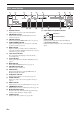
Functional overview Front panel display a b c d DVR t e V-AUX f DTV/CBL g MD/CD-R DVD DOCK VIRTUAL ENHANCER TUNER h CD AUTO TUNED STEREO MEMORY PRESET SLEEP MUTE SP SILENT CINEMA NIGHT AB q DIGITAL q PL ft q PL mS dB PCM j a k l m Decoder indicator Lights up when any of the decoders of this unit functions.
Functional overview Remote control AMP i SCENE 1/2/3/4 Press this button before you control this unit (see page 17). c b POWER POWER TV AV A B STANDBY POWER C MUTE d Recalls an input source and a sound field program assigned to each SCENE button (see page 21). j BAND LEVEL TITLE k MENU l Cursors (l / h / n / k) / ENTER Selects the speaker that you want to adjust (see page 19). e CD MD/CD-R TUNER INTRODUCTION h a Displays the set menu on the front panel display (see page 32).
Functional overview Rear panel a b c d e f ANTENNA OUT DOCK DTV/CBL DVR CENTER FRONT B HDMI COMPONENT VIDEO DVD SPEAKERS SURROUND DTV/CBL DVD MONITOR OUT AM PR GND DIGITAL INPUT VIDEO PB DVD DTV/CBL DVR IN OUT MONITOR OUT FM UNBAL.
Quick start guide The following steps describe the easiest way to operate this unit. See the related pages for details on the operation and settings. Step 3: Connect your components In these steps, you need the following items which are not included in the package of this unit. ❏ Speakers We recommend magnetically shielded speakers. ❏ Center speaker ................................... x 1 ❏ Surround speaker .............................. x 2 ❏ Active subwoofer ...................................
PREPARATION Preparation of remote control Installing batteries in the remote control 1 3 Using the remote control The remote control transmits a directional infrared ray. Be sure to aim the remote control directly at the remote control sensor on this unit during operation. 2 30º 1 Take off the battery compartment cover. 2 Insert the four supplied batteries (AAA, R03, UM-4) according to the polarity markings (+ and –) on the inside of the battery compartment.
Connections Placing speakers Connecting speakers FL C FR SL SR 60˚ SL 80˚ SR ■ 5.1-channel speaker connection d ANTENNA D f e g SPEAKERS SURROUND R L DTV/CBL HDMI CENTER FRONT B L R ADDITIONAL INFORMATION Surround left and right speakers (SL and SR) The surround speakers are used for effect and surround sounds. c ADVANCED OPERATION Center speaker (C) The center speaker is for the center channel sounds (dialog, vocals, etc.).
Connections Speakers Jacks on this unit a Front speaker (A) Right* FRONT A (R) b Front speaker (A) Left* FRONT A (L) c Surround speaker Right SURROUND (R) d Surround speaker Left SURROUND (L) e Center speaker CENTER f Front speaker (B) Right* FRONT B (R) g Front speaker (B) Left* FRONT B (L) h Subwoofer SUBWOOFER * You can select the front speaker set from Front speakers (A) and Front speakers (B) by pressing CSPEAKERS repeatedly. See page 18 for details.
Connections VIDEO jacks For conventional composite video signals transmitted via composite video cables. Connecting video components Audio jacks and cable plugs AUDIO R L DIGITAL AUDIO DIGITAL AUDIO COAXIAL OPTICAL COMPONENT VIDEO jacks For component signals, separated into the luminance (Y) and chrominance (PB, PR) video signals transmitted on separate wires of component video cables.
Connections Connecting a TV monitor or projector Make sure that this unit and other components are unplugged from the AC wall outlets. Note • If you turn off the video monitor connected to the HDMI OUT jack via a DVI connection, the connection may fail. In this case, the HDMI indicator flashes irregularly.
Connections Connecting other components This unit has three types of audio jacks, two types of video jacks and HDMI jacks. You can choose the connection method depending on the component to be connected. ■ Connecting example (connecting a DVD player) DVD SU R DTV/CBL HDMI DOCK DVD PREPARATION ANTENNA OUT COMPONENT VIDEO DTV/CBL DVR MONITOR OUT AM PR GND VIDEO DIGITAL INPUT PB DVD DVR DTV/CBL MONITOR OUT OUT IN FM 75 UNBAL.
Connections Component Signal type DVD recorder CD player MD or CD recorder Jacks on component Jacks on this unit Video HDMI out* HDMI (DVR)* Video out (composite) VIDEO (DVR IN) Audio Audio out (analog)* AUDIO (IN (PLAY))* Audio recording Audio in (analog)* AUDIO (OUT (REC))* Video recording Video in (composite)* VIDEO (DVR OUT)* Audio Coaxial out* OPTICAL (CD)* Audio out (analog) AUDIO (CD) Audio Audio out (analog)* AUDIO (IN (PLAY))* Audio recording Audio in (analog)* AUDIO
Connections Using the VIDEO AUX jacks on the front panel Connecting the wire of the AM loop antenna Insert Close the lever INTRODUCTION Open the lever Use the VIDEO AUX jacks on the front panel to connect a game console or a video camera to this unit. To reproduce the source signals input at these jacks, select “V-AUX” as the input source. Caution Be sure to turn down the volume of this unit and other components before making connections.
Basic setup The “BASIC SETUP” feature is a useful way to set up your system quickly and with minimal effort. Choice Notes • Make sure that you disconnect your headphones from this unit. • If you wish to configure this unit manually using more precise adjustments, use the detailed parameters in “SOUND MENU” (see page 32). • Altering any parameters in “BASIC SETUP” resets all parameters manually adjusted in “SOUND MENU” (see page 32). • Initial settings are indicated by (*) in the following each parameters.
BASIC OPERATION Playback 5 Rotate PVOLUME (or press mVOLUME +/–) to adjust the volume to the desired output level. PREPARATION Basic procedure 1 3 Turn on external components (TV, DVD player, etc.) connected to this unit. Press CSPEAKERS repeatedly to select the front speakers you want to use. The respective speaker indicators lights up on the front panel display. • See page 19 to adjust the level of each speaker. • This does not affect the AUDIO OUT (REC) level.
Playback ■ Guide to contents When you want... See page Adjust the tonal quality of the front speakers 19 Edit parameters of sound field programs 26 Enjoy the sources which have wide dynamic range at night 19 Use headphones 19 Select a decoder to play back sources with 26 Set this unit to the standby mode automatically 20 Using input setting features Use the following features to select input jack or input source.
Playback y Using audio features • Once you press jBAND LEVEL TITLE on the remote control, you can also select the speaker by pressing lk / n. • The available speaker channels differ depending on the speaker settings. ■ 2 Muting the audio output Press eMUTE on the remote control to mute the audio output. Press eMUTE again to resume the audio output. y ■ Adjusting the tonal quality Use this feature to adjust the balance of bass and treble for the front left and right speaker channels.
Playback 2 Press ll / h to adjust the effect level while “NIGHT:CINEMA” or “NIGHT:MUSIC” is displayed on the front panel display. Each choice is defined as follows. Choice Function MIN Slightly lowers the effect level. MID* Moderately lowers the effect level. MAX Considerably lowers the effect level. ■ Using the sleep timer Use this feature to automatically set this unit to the standby mode after a certain amount of time.
Selecting the SCENE templates This unit is equipped with 13 preset SCENE templates for various situations. The following SCENE templates are assigned to respective SCENE buttons in the default settings. SCENE 1 If you want to use other SCENE templates, you can select the desired SCENE templates from the SCENE template library and assign the templates to the selected SCENE buttons on the front panel and the remote control.
Selecting the SCENE templates Which SCENE template would you like to select? The following tables indicate preset SCENE template descriptions. Select the corresponding SCENE templates for the desired source. The illustrations of the SCENE button in the following table indicate that the SCENE templates in those cells are assigned to the SCENE buttons, respectively. You can also create your original SCENE templates by editing the preset SCENE templates. See page 23 for details.
Selecting the SCENE templates ■ Video games SCENE template Playback mode V-AUX Game Features Select this SCENE template when you play video games. Note • When an iPod is connected to the Yamaha iPod universal dock or a Bluetooth component is connected to the Bluetooth receiver, this unit plays back the audio sources input at the DOCK terminal. 2 You can create your original SCENE templates for each SCENE button. Refer to the preset 13 SCENE templates to create the original SCENE templates.
Selecting the SCENE templates Using remote control on the SCENE feature Controlling the input source components in the SCENE mode You can operate both this unit and the input source component by using the remote control. You must set the appropriate remote control code for each input source in advance (see page 39). 1 Press the desired iSCENE button on the remote control. 2 Press the desired buttons in the * area below to control the input source component of the selected SCENE template.
Sound field programs Selecting sound field programs y • Choose a sound field program based on your listening preference, not merely on the name of the program itself. • You can select “Music Enh. 2ch” and “Music Enh. 5ch” by pressing rENHANCER repeatedly. Sound field program descriptions PREPARATION Press LPROGRAM l / h (or press hAMP and then press qPROG l / h repeatedly). The name of the selected sound field program appears on the front panel display.
Sound field programs ■ Selecting decoders for 2-channel sources (surround decode mode) Signals input from 2-channel sources can also be played back on multi-channels. Press hAMP and then press sSUR. DECODE repeatedly to select a decoder. You can select from the following decoders depending on the type of source you are playing and your personal preference.
FM/AM tuning 4 Overview ■ Frequency tuning mode You can search or specify the frequency of the desired FM/AM station automatically or manually (see “FM/AM tuning operations” on this page). Lights up AUTO TUNED A • To tune into a higher frequency, press FPRESET/TUNING h. • To tune into a lower frequency, press FPRESET/ TUNING l. Note • Orient the connected AM loop antenna, or adjust the position of the end of the indoor FM antenna for the best reception.
FM/AM tuning y • You can select the preset station group and the preset station number where the first received station will be stored by pressing EA/B/C/D/E and then FPRESET/TUNING l / h. 1 Press EA/B/C/D/E (or ll / h) repeatedly to select the desired preset station group (A to E). The preset station group letter appears on the front panel display and changes each time you press the button. 2 Press FPRESET/TUNING l / h (or lk / n) to select the desired preset station number (1 to 8).
Using iPod™ Once you have stationed your iPod in a Yamaha iPod universal dock (such as the YDS-11, sold separately) connected to the DOCK terminal of this unit (see page 14), you can enjoy playback of your iPod using the supplied remote control. ■ Stationing your iPod to the Yamaha iPod universal dock Once you station your iPod to the Yamaha iPod universal dock, “iPod connected” and the DOCK indicator appears on the front panel display when “V-AUX” is selected as the input source.
Using Bluetooth™ components You can connect a Bluetooth Wireless Audio Receiver (such as YBA-10, sold separately) to the DOCK terminal of this unit and enjoy the music contents stored in your Bluetooth component (such as a portable music player) without wiring between this unit and the Bluetooth component. You need to perform “pairing” for the connected Bluetooth receiver and your Bluetooth component in advance.
ADVANCED OPERATION Set menu Basic setup BASIC SETUP Use this feature to automatically adjust speaker and system parameters (see page 16). Manual setup MANUAL SETUP ■ Sound menu 1 SOUND MENU Use this menu to manually adjust any speaker settings, alter the quality and tone of the sound output by the system or compensate for video signal processing delays when using LCD monitors or projectors. Parameter Features Page 32 B)SP LEVEL Adjusts the output level of each speaker.
Set menu Using set menu Use the remote control to access and adjust each parameter. y • You can change the set menu parameters while this unit is reproducing sound. 1 2 Press hAMP and then press kMENU on the remote control. “BASIC SETUP” appears on the front panel display. Press lk / n to select “MANUAL SETUP.” . MANUAL SETUP 3 Press lENTER to enter “MANUAL SETUP.” “1 SOUND MENU” appears on the front panel display.
Set menu LFE signals output Choice Notes Front speakers Other speakers BOTH* Output No output No output SWFR Output No output No output No output Output No output FRONT Low-frequency signals output Choice Front speakers Other speakers *1 *2 *3 SWFR *4 *3 *3 FRONT No output *1 *3 Notes ■ Crossover CROSSOVER Use this feature to select a crossover frequency of all the speakers set to “SML” (or “SMALL”) or to “NONE” in “SPEAKER SET” (see pages 31 and 32).
Set menu ■ Test tone TEST Use this feature to make adjustments for “CENTER GEQ” while listening to a test tone. Choice Function OFF* Stops test tones and output the currently. ON Outputs test tones from the center and from left speakers. Low-frequency effect level E)LFE LEVEL Use this feature to adjust the output level of the LFE (lowfrequency effect) channel according to the capacity of your subwoofer or headphones.
Set menu B)INPUT RENAME Input rename Decoder mode The following is an example where “DVD” is renamed “My DVD.” DVR DVD 2 MD/CD-R TUNER CD My DVD Press one of the input selector buttons (f) or vMULTI CH IN to select the input source you want to change the name of. Press hAMP and then press ll / h on the remote control to place the “_” (underscore) under the space or the character you want to edit. Press lk / n to select the character you want to use and then press ll / h to move to the next space.
Set menu 3 Note • When “MEM.GUARD” is set to “ON,” you cannot select and adjust any other set menu items. Audio select C)AUDIO SELECT Use this feature to designate the default audio input jack select setting for the input sources. Choice Automatically detect the type of input signals and select the appropriate input mode. LAST Automatically select the last input mode used for the connected input source (see page 18). Parameter initialization D)PARAM.
Remote control features - Controlling this unit, a TV, or other components ■ Controlling this unit Press hAMP to control this unit. POWER STANDBY POWER TV AV A B C MUTE CD MD/CD-R TUNER DVD DTV/CBL DVR V-AUX/DOCK D TV CH TV INPUT TV MUTE DTV/CBL SCENE 1 2 STANDBY POWER AV A B C MUTE CD MD/CD-R TUNER TV VOL AMP BAND LEVEL TITLE POWER TV E *1 AMP POWER PREPARATION POWER ■ Controlling a TV Press fDTV/CBL to control your TV.
Remote control features ■ Controlling other components Press one of the input selector buttons (f) or A to E buttons to control other components. You must set the appropriate remote control code for each input source in advance (see page 39). The following table shows the function of each control button used to control other components assigned to each input selector button. Be advised that some buttons may not correctly operate the selected component.
Remote control features 2 Setting remote control codes Remote control code default settings Input source Component category Manufacturer Notes Default code 5013 5001 TUNER TUNER Yamaha 5007 DVD DVD Yamaha 2000 DTV/CBL — — — V-AUX/ DOCK TUNER Yamaha 5011 DVR DVR Yamaha 2011 A TUNER Yamaha 5012 B TUNER Yamaha 5009 C TUNER Yamaha 5017 D — — — E — — — ■ Resetting all remote control codes Use this feature to clear all the remote control codes previously set and rese
Advanced setup This unit has additional menus that are displayed on the front panel display. The advanced setup menu offers additional operations to adjust and customize the way this unit operates. Change the initial settings (indicated by (*) in this following parameter) to reflect the needs of your listening environment. Notes • Only ASTANDBY/ON, LPROGRAM l / h and MSTRAIGHT are effective while you are using the advanced setup menu.
ADDITIONAL INFORMATION Troubleshooting ■ General Problem The power cable is not connected or the plug is not completely inserted. Connect the power cable firmly. — The speaker impedance setting is incorrect. Set the speaker impedance to match your speakers. 40 The protection circuitry has been activated. Make sure that all speaker wire connections on this unit and on all speakers are secure and that the wire for each connection does not touch anything other than its respective connection.
Troubleshooting Problem Cause Remedy See page Sound is heard from the speaker on one side only. Incorrect cable connections. Connect the cables properly. If the problem persists, the cables may be defective. Incorrect settings in “SP LEVEL.” Adjust the “SP LEVEL” settings. 33 Only the center speaker outputs substantial sound. When playing a monaural source with a CINEMA DSP program, the source signal is directed to the center channel, and the front and surround speakers output effect sounds.
Troubleshooting This unit does not operate properly. The internal microcomputer has been frozen by an external electric shock (such as lightning or excessive static electricity) or by a power supply with low voltage. Disconnect the power cable from the AC wall outlet and then plug it in again after about 30 seconds. — “CHECK SP WIRES” appears on the front panel display. Speaker cables are short-circuited. Make sure all speaker cables are connected correctly.
Troubleshooting Problem AM ■ Cause The desired station cannot be tuned into with the automatic tuning method. The signal is weak or the antenna connections are loose. There are continuous crackling and hissing noises. There are buzzing and whining noises. Remedy See page Tighten the AM loop antenna connections and orient it for the best reception. — Use the manual tuning method. 27 Noises result from lightning, fluorescent lamps, motors, thermostats and other electrical equipment.
Troubleshooting ■ Remote control Problem Remedy See page The remote control functions within a maximum range of 6 m (20 ft) and no more than 30 degrees offaxis from the front panel. 8 Direct sunlight or lighting (from an inverter type of fluorescent lamp, etc.) is striking the remote control sensor of this unit. Reposition this unit. — The batteries are weak. Replace all batteries. 8 The remote control code is not correctly set.
Glossary ■ Audio information Dolby Digital Dolby Digital is a digital surround sound system that gives you completely independent multi-channel audio. With 3 front channels (front L/R and center), and 2 surround stereo channels, Dolby Digital provides 5 full-range audio channels. With an additional channel especially for bass effects, called LFE (Low Frequency Effect), the system has a total of 5.1-channels (LFE is counted as 0.1 channel).
Specifications AUDIO SECTION • Maximum Power (JEITA) [U.S.A. and Canada models] 1 kHz, 10% THD, 8 Ω ................................................ 135 W/ch [Asia, China, Korea and General models] 1 kHz, 10% THD, 6 Ω ................................................. 135 W/ch • IEC Power [U.K., Russia, and Europe models] 1 kHz, 0.1% THD, 6 Ω ........................................ 90 W or more • Video Maximum Input Level ................................ 1.5 Vp-p or more • Signal to Noise Ratio .........
Index ■ Numerics 1 SOUND MENU .................................... 31, 32 2 INPUT MENU ...................................... 31, 34 2ch Stereo ...................................................... 25 3 OPTION MENU ................................... 31, 35 5ch Stereo ...................................................... 25 ■ A A)DISPLAY SET .......................................... 35 A)INPUT ASSIGN ........................................ 34 A)SPEAKER SET .........................................
Index ■ O Option menu ...................................................31 ■ P R ■ S U UNIT .............................................................. 33 Unit ................................................................ 33 Unknown iPod, iPod controlling status message ..................................................... 44 Using the remote control ................................. 8 Using the VIDEO AUX jacks ........................ 15 Using your headphones ..............................
PRÉCAUTIONS CONCERNANT LA SÉCURITÉ 10 CAUTION RISK OF ELECTRIC SHOCK DO NOT OPEN ATTENTION: POUR RÉDUIRE LES RISQUES D’INCENDIE ET DE DÉCHARGE ELECTRIQUE, NE PAS RETIRER LE COUVERCLE (OU LE PANNEAU ARRIÈRE). NE CONTIENT AUCUNE PIÈCE INTERNE RÉPARABLE PAR L’UTILISATEUR. POUR L’ENTRETIEN, S’ADRESSER À UN PERSONNEL QUALIFIÉ.
PRÉCAUTIONS CONCERNANT LA SÉCURITÉ d) 20 21 22 23 L’appareil ne fonctionne pas selon les instructions du manuel. N’utiliser que les commandes décrites dans le mode d’emploi, car un réglage inadéquat de toute autre commande peut entraîner des dommages exigeant des réparations onéreuses par un technicien qualifié; e) L’appareil est tombé ou a été endommagé d’une autre manière, f) Les performances de ce produit changent de manière significative.
Attention: Veuillez lire ce qui suit avant d’utiliser l’appareil. 1 Pour utiliser l’appareil au mieux de ses possibilités, lisez attentivement ce mode d’emploi. Conservez-le soigneusement pour référence. 2 Installez cet appareil audio dans un endroit bien aéré, frais, sec et propre – à l’abri de la lumière directe du soleil, des sources de chaleur ou de vibration, des poussières, de l’humidité et du froid.
TABLE DES MATIÈRES INTRODUCTION OPÉRATIONS DÉTAILLÉES Menu de réglage.................................................... 31 Accessoires fournis .................................................... 2 Utilisation du menu de réglage ................................ 32 1 SOUND MENU.................................................... 32 2 INPUT MENU...................................................... 34 3 OPTION MENU ................................................... 35 Aperçu des fonctions..............
INTRODUCTION Description Amplificateur intégré à 5 voies ◆ Puissance minimum de sortie efficace [Modèles pour les États-Unis et le Canada] (1 kHz, DHT 0,9%, 8 Ω) Voies avant: 100 W/ch Voie centrale: 100 W Voies d’ambiance: 100 W/ch [Autres modèles] (1 kHz, DHT 0,9%, 6 Ω) Voies avant: 100 W/ch Voie centrale: 100 W Voies d’ambiance: 100 W/ch Connecteurs d’entrée/de sortie Fabriqué sous licence de numéros de brevet américain: 5,451,942;5,956,674;5,974,380;5,978,762;6,487,535 et d’autres brevets américains et
Aperçu des fonctions Face avant C D E F G H I P VOLUME EDIT PRESET/TUNING l A/B/C/D/E PRESET/TUNING h BAND MEMORY PRÉPARATIONS SPEAKERS TUNING AUTO/MAN'L SCENE 1 PHONES TONE CONTROL PROGRAM l STANDBY /ON 2 l EFFECT VIDEO B K L STANDBY/ON M C SPEAKERS Commande de VOLUME Q Prise VIDEO (VIDEO AUX) F PRESET/TUNING l / h Sélectionne le groupe de présélection (de A à E) (voir page 28).
Aperçu des fonctions Afficheur de la face avant a b c d DVR t e V-AUX f DTV/CBL g MD/CD-R DVD DOCK VIRTUAL ENHANCER TUNER h CD SP SILENT CINEMA NIGHT AB ft q PL mS dB PCM j a k l m Témoin de décodeur n p Lorsque l’un des décodeurs de l’appareil est en fonctionnement, le témoin s’allume. b Témoin ENHANCER Ce témoin s’éclaire lorsque le mode Compressed Music Enhancer est sélectionné (voir page 25).
Aperçu des fonctions Boîtier de télécommande Boutons de commande de TV h AMP Commande votre téléviseur (voir page 37). c b POWER POWER TV AV A B STANDBY POWER C MUTE d Appuyez sur ce bouton avant de commande cet appareil (voir page 17). i Rappelle une source d’entrée et une correction de champ sonore assignées à chaque bouton SCENE (voir page 21).
Aperçu des fonctions Panneau arrière a b c d e f ANTENNA OUT DOCK DTV/CBL DVR CENTER FRONT B HDMI COMPONENT VIDEO DVD SPEAKERS SURROUND DTV/CBL DVD MONITOR OUT AM PR GND DIGITAL INPUT VIDEO PB DVD DTV/CBL DVR IN OUT MONITOR OUT FM UNBAL.
Guide de démarrage rapide Les étapes suivantes décrivent la manière la plus facile d’utiliser cet appareil. Reportez-vous aux pages connexes pour plus de détails sur le fonctionnement et les réglages. Étape 3: Raccordez vos appareils Pour ces étapes, vous avez besoin des éléments suivants qui ne sont pas inclus dans l’emballage de cet appareil. ❏ Enceintes Nous recommandons des enceintes à blindage magnétique. ❏ Câble d’enceinte ..................................... x 5 ❏ Câble de caisson de graves .....
PRÉPARATIONS Préparation du boîtier de télécommande Mise en place des piles dans le boîtier de télécommande 1 3 Utilisation du boîtier de télécommande Le boîtier de télécommande émet un rayon infrarouge. Veillez à le pointer directement sur le capteur de télécommande de l’appareil pour en assurer le fonctionnement. 2 30º 1 Détachez le couvercle du logement des piles. 2 Insérez les quatre piles fournies (AAA, R03, UM-4) en respectant les polarités (+ et –) indiquées dans le logement.
Raccordements Disposition des enceintes Raccordements des enceintes FL C FR SL SR 60˚ SL 80˚ SR ■ Raccordement des enceintes pour un ensemble à 5.1 voies d f e g INFORMATIONS COMPLÉMENTAI RIES c Enceintes d’ambiance gauche et droite (SL et SR) Les enceintes d’ambiance restituent les effets sonores et les sons d’ambiance. ANTENNA D SPEAKERS SURROUND R L DTV/CBL HDMI CENTER FRONT B L R AM GND VIDEO BL DVR MONITOR OUT OUT IN FM 75 UNBAL.
Raccordements Enceintes Prises sur cet appareil a Enceinte avant (A) droite* FRONT A (R) b Enceinte avant (A) gauche* FRONT A (L) c Enceinte d’ambiance droite SURROUND (R) d Enceinte d’ambiance gauche SURROUND (L) e Enceinte centrale CENTER f Enceinte avant (B) droite* FRONT B (R) g Enceinte avant (B) gauche* h Caisson de graves Raccordement aux bornes FRONT A 2 1 Rouge: pôle positif (+) Noir: pôle négatif (–) 3 1 Desserrez la borne.
Raccordements Raccordement d’appareils vidéo Prises audio et fiches des câbles AUDIO R L DIGITAL AUDIO DIGITAL AUDIO COAXIAL OPTICAL Prises COMPONENT VIDEO Ces prises sont destinées aux signaux à composantes, séparés en signaux vidéo de luminance (Y) et signaux vidéo de chrominance (PB, PR) transmis séparément via des câbles vidéo à composantes.
Raccordements Raccordement d’un moniteur TV ou d’un projecteur Assurez-vous que cet appareil et les autres appareils sont débranchés des prises secteur. Remarque • Si vous éteignez le moniteur vidéo raccordé à la prise HDMI OUT via une liaison DVI, la connexion risque d’échouer. Dans ce cas, le témoin HDMI clignote de façon irrégulière.
Raccordements Raccordement d’autres appareils Cet appareil dispose de trois types de prises audio, deux types de prises vidéo et de prises HDMI. Choisissez le type de prises en fonction de l’appareil que vous comptez connecter. ■ Exemple de raccordement (connexion d’un lecteur de DVD) PRÉPARATIONS ANTENNA OUT DVD SU R DTV/CBL HDMI DOCK DVD COMPONENT VIDEO DTV/CBL DVR MONITOR OUT AM PR GND VIDEO DIGITAL INPUT PB DVD DVR DTV/CBL MONITOR OUT OUT IN FM 75 UNBAL.
Raccordements Appareil Format du signal Graveur de DVD Lecteur de CD Enregistreur de MD ou graveur de CD Prises sur l’appareil Prises sur cet appareil Vidéo Sortie HDMI* HDMI (DVR)* Sortie vidéo (composite) VIDEO (DVR IN) Audio Sortie audio (analogique)* AUDIO (IN (PLAY))* Enregistrement audio Entrée audio (analogique)* AUDIO (OUT (REC))* Enregistrement vidéo Entrée vidéo (composite)* VIDEO (DVR OUT)* Audio Sortie coaxiale* OPTICAL (CD)* Sortie audio (analogique) AUDIO (CD) Audio
Raccordements Utilisation des prises VIDEO AUX sur la face avant Raccordement du fil de l’antenne cadre AM Insérez Fermez le levier INTRODUCTION Ouvrez le levier Reliez votre console de jeu ou votre caméscope aux prises VIDEO AUX sur la face avant de l’appareil. Pour reproduire les signaux de la source raccordée à ces prises, sélectionnez “V-AUX” comme source d’entrée. Attention Veillez à réduire complètement le volume de cet appareil et des autres appareils avant de les relier.
Réglage de base La fonction “BASIC SETUP” est une manière utile de configurer rapidement et avec un minimum d’efforts votre système. Choix Remarques • Assurez-vous de débrancher le casque de l’appareil. • Si vous souhaitez configurer cet appareil manuellement à l’aide de réglages plus précis, utilisez les paramètres détaillés dans “SOUND MENU” (voyez page 32). • La modification de tout paramètre dans “BASIC SETUP” réinitialise manuellement tous les paramètres réglés dans “SOUND MENU” (voyez page 32).
OPÉRATIONS DE BASE Lecture 5 Tournez PVOLUME (ou appuyez sur mVOLUME +/–) pour régler le volume au niveau d’émission souhaité. PRÉPARATIONS Opérations de base 1 Appuyez à plusieurs reprises sur CSPEAKERS pour sélectionner les enceintes avant que vous souhaitez utiliser. Les indicateurs d’enceinte respectifs s’allument sur l’afficheur de la face avant.
Lecture ■ Table des matières Lorsque vous souhaitez...
Lecture y Utilisation des fonctions audio • Une fois que vous avez appuyé sur jBAND LEVEL TITLE sur le boîtier de télécommande, vous pouvez également sélectionner l’enceinte à l’aide de lk / n. • Les voies d’enceinte disponibles dépendent des réglages des enceintes. ■ 2 Mise en sourdine du son Appuyez sur eMUTE sur le boîtier de télécommande pour mettre le son en sourdine. Appuyez une nouvelle fois sur eMUTE pour rétablir le son.
Lecture y • “Les réglages NIGHT:CINEMA” et “NIGHT:MUSIC” sont enregistrés séparément. Remarques • Il vous est impossible d’utiliser les modes d’écoute nocturne dans les cas suivants: – lorsque l’appareil raccordé aux prises MULTI CH INPUT est sélectionné comme source d’entrée. – lorsque le casque est relié à la prise PHONES. – lorsque la fréquence d’échantillonnage des sources d’entrée est supérieure à 48 kHz.
Sélection de modèles SCENE Touche SCENE par défaut Sélectionnez le modèle de SCENE souhaité Le nom du modèle SCENE et sa description SCENE 3 TV Viewing *1 – source d’entrée: DTV/CBL – correction de champ sonore: STRAIGHT Pour quand vous souhaitez regarder un programme télévisé. Attribuez le modèle de SCENE à la touche SCENE Bibliothèque des modèles de SCENE (Image) 1 DVD Viewing 2 Appuyez sur NINPUT l / h (ou appuyez sur hAMP, ensuite, sur ll / h) pour sélectionner le modèle souhaité.
Sélection de modèles SCENE Quel modèle de SCENE voulez-vous sélectionner ? Les tableaux suivants affichent des descriptions de modèles de SCENE préréglés. Sélectionnez les modèles de SCENE correspondant à la source souhaitée. Dans le tableau suivant, les illustrations de la touche SCENE indiquent que les modèles de SCENE dans ces cellules sont attribués aux touches SCENE, respectivement. Vous pouvez également créer vos modèles de SCENE originaux en éditant les modèles de SCENE préréglés.
Sélection de modèles SCENE ■ Jeux vidéo Modèle de SCENE Mode lecture V-AUX Game Description Sélectionnez ce modèle de SCENE lorsque vous jouez à des jeux vidéo. Remarque • Lorsqu’un iPod est raccordé à la station universelle Yamaha iPod ou qu’un appareil Bluetooth est raccordé à l’ampli-syntoniseur Bluetooth, cet appareil lit les sources audio transmises à la borne DOCK. 2 Vous pouvez créer vos modèles de SCENE d’origine pour chaque touche de SCENE.
Sélection de modèles SCENE Utilisation de la télécommande sur la fonction SCENE Commande des appareils de source d’entrée en mode SCENE Vous pouvez utiliser cet appareil et l’appareil de source d’entrée à l’aide du boîtier de télécommande. Vous devez spécifier au préalable le code de commande à distance approprié pour chaque source (voyez page 39). 1 Appuyez sur la touche iSCENE souhaitée sur le boîtier de télécommande.
Corrections de champ sonore Sélection d’une correction de champ sonore y • Choisissez la correction de champ sonore en fonction de vos préférences et non pas en vous basant uniquement sur son nom. • Vous pouvez sélectionner “Music Enh. 2ch” et “Music Enh. 5ch” en appuyant à plusieurs reprises sur rENHANCER. PRÉPARATIONS Appuyez sur LPROGRAM l / h (ou appuyez sur hAMP, ensuite, appuyez à plusieurs reprises sur qPROG l / h ).
Corrections de champ sonore ■ Sélection de décodeurs pour les sources à 2 voies (mode de décodage d’ambiance) Les entrées de signaux de sources à 2 voies peuvent également être lues sur des multivoies. Appuyez sur hAMP, ensuite, appuyez sur sSUR. DECODE à plusieurs reprises pour sélectionner un décodeur. Vous avez le choix entre les décodeurs suivants selon le type de source que vous lisez et vos goûts personnels.
Syntonisation FM/AM 4 Vue d’ensemble ■ Mode de syntonisation de fréquences Vous pouvez rechercher ou spécifier la fréquence de la station FM/AM désirée automatiquement ou manuellement (voir “Syntonisation FM/AM” ci-après). S’éclaire AUTO TUNED A AM 1530 kHz • Orientez l’antenne cadre AM raccordée ou ajustez la position de l’extrémité de l’antenne FM intérieure pour obtenir la meilleure réception. Syntonisation FM/AM Remarque 2 Appuyez sur GBAND pour sélectionner la bande de réception (FM ou AM).
Syntonisation FM/AM y • Vous pouvez sélectionner le groupe de station préréglé et le numéro de station préréglé où la première station reçue sera enregistrée en appuyant sur EA/B/C/D/E et, ensuite, sur FPRESET/TUNING l / h. 1 Appuyez à plusieurs reprises sur EA/B/C/D/ E (ou ll / h) pour sélectionner le groupe de station préréglé souhaité (A à E). La lettre repérant le groupe de présélections apparaît sur l’afficheur de la face avant et change à chaque pression de la touche.
Utilisation de iPod™ ■ iPod pris en charge iPod (Click and Wheel, y compris iPod classic) iPod nano iPod mini iPod touch ■ Placement de votre iPod sur la station universelle Yamaha iPod Dès que vous placez votre iPod sur la station universelle Yamaha iPod, “iPod connected” et le témoin DOCK apparaît sur l’afficheur de la face avant lorsque “V-AUX” est sélectionné en tant que source d’entrée.
Utilisation d’appareils Bluetooth™ Vous pouvez brancher un Récepteur Audio Sans Fil Bluetooth (tel que le YBA-10 vendu séparément) à la borne DOCK de cet appareil afin de pouvoir écouter la musique en mémoire sur votre appareil Bluetooth (tel qu’un lecteur de musique portable) sans devoir raccorder l’appareil Bluetooth à cet appareil. Il est nécessaire, au préalable, d’effectuer un “jumelage” entre l’ampli-syntoniseur Bluetooth raccordé et votre appareil Bluetooth.
OPÉRATIONS DÉTAILLÉES Menu de réglage Réglage de base BASIC SETUP Utilisez cette option pour régler automatiquement les enceintes et les paramètres de la chaîne (voyez page 16). Réglage manuel MANUAL SETUP ■ Menu du son 1 SOUND MENU Utilisez ce menu pour ajuster manuellement les réglages des enceintes, modifier la qualité et la tonalité du son émis par la chaîne ou compenser les délais de traitement du signal vidéo lors de l’utilisation de moniteurs LCD ou de projecteurs.
Menu de réglage Utilisation du menu de réglage Utilisez le boîtier de télécommande pour accéder et ajuster chaque paramètre. y • Vous pouvez modifier les paramètres de menu de réglage pendant que l’appareil reproduit le son. 1 2 Appuyez sur hAMP, ensuite, appuyez sur kMENU du boîtier de télécommande. “BASIC SETUP” apparaît sur l’afficheur de la face avant. Appuyez sur lk / n pour sélectionner “MANUAL SETUP”. .
Menu de réglage Restitution des signaux LFE Remarques Enceintes avant Autres enceintes BOTH* Sortie Pas de sortie Pas de sortie SWFR Sortie Pas de sortie Pas de sortie FRONT Pas de sortie Sortie Pas de sortie Choix Sortie de signaux des fréquences graves Enceintes avant Autres enceintes BOTH* *1 *2 *3 SWFR *4 *3 *3 FRONT Pas de sortie *1 *3 Remarques Utilisez cette option pour préciser manuellement la distance à chaque enceinte et le retard qui doit être appliqué à la voie c
Menu de réglage ■ Tonalité d’essai TEST Utilisez cette fonction pour effectuer des réglages pour “CENTER GEQ” tout en écoutant une tonalité d’essai. Choix Fonction OFF* Arrête les tonalités d’essai et restitue la tonalité en cours. ON Restitue des tonalités d’essai à partir des enceintes gauche et centrale.
Menu de réglage Voici, ci-dessous un exemple où “DVD” est renommé par “My DVD”. DVR V-AUX MD/CD-R TUNER CD My DVD 2 Appuyez sur hAMP, ensuite, appuyez sur ll / h du boîtier de télécommande pour placer le “_” (soulignement) sous l’espace ou le caractère que vous souhaitez éditer. 3 Appuyez sur lk / n pour sélectionner le caractère que vous souhaitez utiliser, ensuite, appuyez sur ll / h pour passer à l’espace suivant.
Menu de réglage Sélection audio C)AUDIO SELECT 2 Vérifiez que l’appareil Bluetooth détecte l’ampli-syntoniseur Bluetooth. Pour plus de détails, reportez-vous au mode d’emploi de l’appareil Bluetooth. 3 Sélectionnez l’ampli-syntoniseur Bluetooth dans la liste des appareils Bluetooth et saisissez ensuite la clé “0000” sur l’appareil Bluetooth. Une fois le jumelage terminé avec succès, “Completed” s’affiche.
Caractéristiques du boîtier de télécommande - Commande de cet appareil, d’un téléviseur ou d’autres appareils ■ Commande de cet appareil Appuyez sur hAMP pour commander cet appareil.
Caractéristiques du boîtier de télécommande ■ Commande des autres appareils Appuyez sur une des touches de sélection d’entrée (f) ou sur les touches de A à E pour commander d’autres appareils. Vous devez spécifier au préalable le code de commande à distance approprié pour chaque source (voyez page 39). Les fonctions de chaque touche de commande utilisée pour les appareils attribués à chaque touche de sélection d’entrée sont indiquées dans le tableau suivant.
Caractéristiques du boîtier de télécommande 2 Enregistrement des codes de commande Codes de commande enregistrés par défaut Code par défaut CD CD Yamaha 5013 MD/CD-R CD-R Yamaha 5001 TUNER TUNER Yamaha 5007 DVD DVD Yamaha 2000 DTV/CBL — — — V-AUX/ DOCK TUNER Yamaha 5011 DVR DVR Yamaha 2011 A TUNER Yamaha 5012 B TUNER Yamaha 5009 C TUNER Yamaha 5017 D — — — E — — — ■ Réinitialisation de tous les codes de commande à distance Utilisez cette fonction pour eff
Réglages approfondis Cet appareil propose d’autres menus qu’il affiche, le moment venu, sur la face avant. Le menu de réglages approfondis offre le moyen de régler et de personnaliser le fonctionnement de cet appareil. Modifiez le réglage initial (indiqué par * chaque paramètre) pour tenir compte des besoins de votre environnement d’écoute. ■ Impédance des enceintes SP IMP.
INFORMATIONS COMPLÉMENTAIRIES Guide de dépannage ■ Généralités Réglez l’impédance des enceintes sur la valeur correspondant aux enceintes. 40 Le circuit de protection a été activé. Assurez-vous que tous les cordons de liaison aux enceintes sont bien reliés à l’appareil et aux enceintes et qu’aucun cordon n’est en contact avec autre chose que la borne ou la prise qui le concernent.
Guide de dépannage Anomalies Causes possibles Actions correctives Voir page Le son ne sort des enceintes que d’un côté. Les raccordements des câbles sont incorrects. Raccordez correctement les câbles. Si l’anomalie persiste, il se peut que les câbles soient défectueux. Réglages incorrects dans “SP LEVEL”. Ajustez les réglages “SP LEVEL”. 33 Seule l’enceinte centrale émet des sons audibles.
Guide de dépannage Anomalies Causes possibles Actions correctives Voir page Le microprocesseur interne a cessé de fonctionner du fait d’une décharge électrique (provoquée par un orage ou une décharge d’électricité statique), ou d’une baisse importante de la tension d’alimentation. Débranchez le câble d’alimentation puis rebranchezle environ 30 secondes plus tard. — “CHECK SP WIRES” apparaît sur l’afficheur de la face avant. Les câbles d’enceintes sont en courtcircuit.
Guide de dépannage Anomalies AM ■ Causes possibles Actions correctives Il n’est pas possible d’effectuer la syntonisation automatique sur la station désirée. Le signal capté est trop faible, ou les raccordements de l’antenne sont défectueux. Des craquements et des sifflements sont produits en permanence. Vous entendez des bruits sourds et des couinements. Voir page Resserrez les raccordements de l’antenne cadre AM et orientez-la pour que la réception soit aussi bonne que possible.
Guide de dépannage ■ Bluetooth Message d’état Actions correctives Voir page INTRODUCTION Searching... Causes possibles L’ampli-syntoniseur Bluetooth et l’appareil Bluetooth sont en cours de jumelage. L’ampli-syntoniseur Bluetooth et l’appareil Bluetooth sont en train d’établir la connexion. Canceled Le jumelage est annulé. BT connected La connexion entre le Récepteur Audio Sans Fil Bluetooth (tel que le YBA-10 vendu séparément) et l’appareil Bluetooth est établie.
Glossaire ■ Affichage des réglages audio Dolby Digital Dolby Digital est un système numérique de correction d’ambiance acoustique qui produit des voies totalement indépendantes. Avec 3 voies avant (gauche, centre et droite) et 2 voies arrière stéréo, Dolby Digital est un système à 5 voies audio. Une voie supplémentaire, sur laquelle ne circulent que les effets basse fréquence appelée LFE, complète l’ensemble à 5.1 voies (LFE est comptée pour 0.1 voie).
Caractéristiques techniques SECTION AUDIO • Puissance MAX par voie [Modèles au Royaume-Uni, en Russie et en Europe] 1 kHz, 0,7% THD, 4 Ω ....................................... 105 W ou plus • Puissance CEI [Modèles au Royaume-Uni, en Russie et en Europe] 1 kHz, 0,1% THD, 6 Ω ......................................... 90 W ou plus • Entrefer dynamique [Modèles pour les États-Unis et le Canada] 8 Ω ....................................................................................
Index ■ Numerics 1 SOUND MENU .................................... 31, 32 2 INPUT MENU ...................................... 31, 34 2ch Stereo ...................................................... 25 3 OPTION MENU ................................... 31, 35 5ch Stereo ...................................................... 25 ■ A A)DISPLAY SET .......................................... 35 A)INPUT ASSIGN ........................................ 34 A)SPEAKER SET .........................................
Index PROG, boîtier de télécommande ......................5 PROGRAM, face avant ....................................3 Protection de la mémoire ...............................35 ■ R ADVANCED OPERATION ■ BASIC OPERATION U UNIT .............................................................. 33 Unknown iPod, message d’état de commande d’iPod ........................................................ 44 Utilisation d’un casque .................................. 19 Utilisation des prises VIDEO AUX ...........
List of remote control codes Liste des codes de commande Blu-ray Player Samsung 2137 CD Player Yamaha 5000, 5013 CD Recorder Yamaha 5001 DVD 2078 2072 2072 2073 2072 2035 2075 2078 2077 2073, 2135 2075 2075 2074 2030, 2040, 2054, 2057, 2105, 2110 Philips 2019, 2026, 2046, 2073, 2081, 2090 Pioneer 2036, 2082 Proline 2077 Provision 2075 RCA 2031, 2042, 2050, 2051 Red Star 2076 Reoc 2074 Roadstar 2075, 2078, 2086 Rowa 2077 Saba 2085 Sabaki 2074 Samsung 2032, 2041, 2104, 2113 Sansui 2074 Sanyo 2095 ScanM
Akai 0059, 0065, 0127, 0129, 0130, 0200, 0204, 0208, 0209, 0213, 0217, 0218, 0255 Akiba 0209, 0218 Akura 0206, 0209, 0218 Alaron 0200 Alba 0200, 0207, 0208, 0209, 0217, 0218 ALBIRAL 0212 Allstar 0213 Amplivision 0207 Amstrad 0204, 0206, 0208, 0209, 0218 Amtron 0062 Anam 0208 Anam National 0062 Anglo 0208 Anitech 0206, 0208 Ansonic 0203, 0208 AOC 0060, 0061 Apex 0118, 0122, 0132 Arc en Ciel 0216 Arcam 0200 Arcam Delta 0207 Aristona 0213, 0217 ASA 0205, 0211 Asberg 0213 Astra 0208 Asuka 0200, 0206, 0207, 020
Lenco Lenoir Lesa Leyco LG NEC 0026, 0053, 0060, 0061, 0096, 0127 Neckermann 0205, 0207, 0210, 0213, 0217, 0255 NEI 0213, 0217 Nesco 0214 NET-TV 0082, 0101 New Tech 0208, 0213 New World 0209, 0218 Nicamagic 0200, 0207 Nikkai 0200, 0206, 0207, 0209, 0213, 0217, 0218 Nikko 0061 Nobliko 0200, 0207 Nogamatic 0216 Nokia 0129, 0211 Nordmende 0205, 0211, 0213, 0216 Nordvision 0217 Oceanic 0211 Olevia 0084 ONCEAS 0207 Onwa 0062, 0218 Orbit 0213 Orion 0126, 0204, 0208, 0213, 0217, 0235 Orline 0218 Orsowe 0204 Osak
Tandy 0127, 0207, 0209, 0211, 0218 Tashiko 0200, 0207, 0210 Tatung 0127, 0204, 0207, 0213, 0217, 0237 TCM 0206, 0208 Teac 0127 Tec 0207, 0208, 0214, 0215 Techwood 0060, 0061 Teknika 0058, 0060, 0061, 0062 Teleavia 0216 Telecor 0218 Telefunken 0065, 0213, 0216 Telegazi 0218 Teletech 0208, 0214, 0217 Teleton 0207 Televideon 0200 Tensai 0208, 0209, 0213, 0218 Tesmet 0213 Tevion 0206, 0208 Texet 0200, 0207 Thomson 0191, 0192, 0207, 0213, 0216, 0226 Thorn 0212, 0217 TMK 0060, 0061 Tokai 0213 Tokyo 0200, 0207 To
Memorex Randex RCA 1003 1002, 1004, 1009, 1010, 1014, 1015, 1022, 1032 Realistic 1001, 1002, 1003, 1004, 1005, 1008 Rex 1043 RFT 1046 Roadstar 1045, 1050, 1066 Saba 1043 Saisho 1044, 1050 Salora 1047 Samsung 1002, 1014, 1021, 1027, 1052, 1068, 1070 Sanky 1008 Sansui 1007, 1011, 1013, 1043 Sanyo 1001, 1002, 1014, 1047 SBR 1046 Schaub Lorenz 1042, 1043, 1047 Schneider 1042, 1044, 1045, 1046, 1050 Scott 1012 Sears 1001, 1003, 1004, 1010 SEG 1050 SEI-Sinudyne 1046 Seleco 1043 Sentron 1050 Sharp 1008, 1023, 10
© 2009 Yamaha Corporation All rights reserved.