
Service manual


18
RX-V365/HTR-6230
RX-V365/HTR-6230
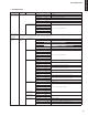
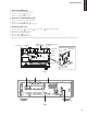
MAIN (1) P.C.B.
G105
ST101
G103
G104
Ground lead
Chassis
Ground lead
Rear panel
Ground lead
11
11 12
11
Rear panel
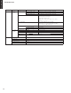
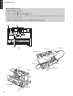
MF117350
CB408
CB202
DSP P.C.B.
OPERATION (1) P.C.B.
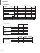
Fig. 4
Fig. 6
Fig. 5
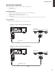
When checking the P.C.B.
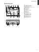
a. Remove the top cover. (Fig. 1)
b. Remove 3 screws (
). (Fig. 3)
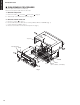
c. Remove 5 screws (
) and 4 screws ( ). (Fig. 4)
d. Place the P.C.B.s (with rear panel) upright. (Fig. 5)
e. Connect the ground of heat sink, rear panel and MAIN (1) P.C.B. (G103, G104, G105 and ST101) to the chassis with a
ground lead or the like. (Fig. 5)
• Use the extension cable for connection for the following connectors. (Fig. 6)
DSP P.C.B. CB408 – OPERATION (1) P.C.B. CB202: MF117350 (17P, 350mm)