AV Receiver Owner’s Manual English Read the supplied booklet “Safety Brochure” before using the unit.
CONTENTS Accessories . . . . . . . . . . . . . . . . . . . . . . . . . . . . . . . . . . . . . . . . . . . . . . . . . . . . . . 5 7 Connecting other devices . . . . . . . . . . . . . . . . . . . . . . . . . . . . . . . . . . . . . . 33 Connecting an external power amplifier . . . . . . . . . . . . . . . . . . . . . . . . . . . . . . . . . . . . . . . . . . . . . . . . . . . . . . . . . . . 33 FEATURES 6 Connecting recording devices . . . . . . . . . . . . . . . . . . . . . . . . . . . . . . . . . . . .
Radio Data System tuning . . . . . . . . . . . . . . . . . . . . . . . . . . . . . . . . . . . . . . . . . . . . . . . . . . . . . . . . . . . . . . . . . . . . . . . . . 55 Sound Program menu items . . . . . . . . . . . . . . . . . . . . . . . . . . . . . . . . . . . . . . . . . . . . . . . . . . . . . . . . . . . . . . . . . . . . . . . 86 Operating the radio on the TV . . . . . . . . . . . . . . . . . . . . . . . . . . . . . . . . . . . . . . . . . . . . . . . . . . . . . . . . . . . . . . . . . . . .
APPENDIX 112 Frequently asked questions . . . . . . . . . . . . . . . . . . . . . . . . . . . . . . . . . . . . 112 Troubleshooting . . . . . . . . . . . . . . . . . . . . . . . . . . . . . . . . . . . . . . . . . . . . . . . 113 Power and system . . . . . . . . . . . . . . . . . . . . . . . . . . . . . . . . . . . . . . . . . . . . . . . . . . . . . . . . . . . . . . . . . . . . . . . . . . . . . . . 113 Audio . . . . . . . . . . . . . . . . . . . . . . . . . . . . . . . . . . . . . . . . . . . . . . . .
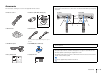
Accessories Operating range of the remote control Check that the following accessories are supplied with the product. • Point the remote control at the remote control sensor on the unit and remain within the operating range shown below. Remote control Batteries (AAA, R03, UM-4) (x2) (HTR-7065) (HTR-6065) Within 6 m (20 ft) 30° 30° 30° 30° Insert the batteries the right way round. AM antenna FM antenna *One of the above is supplied depending on the region of purchase.
FEATURES What you can do with the unit Wide variety of supported content • iPod/iPhone/iPad . p.58 • USB . p.62 • Media server (PC/NAS) . p.65 • Internet radio . p.68 • AirPlay . p.70 Supports 2- to 7.1-channel (plus presence) speaker system. Allows you to enjoy your favorite acoustic spaces in various styles. • Automatically optimizing the speaker . p.37 settings to suit your room (YPAO) • Reproducing stereo or multichannel . p.
Full of useful functions! Useful tips ❑ Connecting various devices (p.28) ❑ Creating 3-dimensional sound fields (p.48) A number of HDMI jacks and various input/output jacks on the unit allow you to connect video devices (such as BD/DVD players), audio devices (such as CD players), game consoles, camcorders, and other devices. Connecting presence speakers allows you to create a natural 3-dimensional sound field in your own room (CINEMA DSP 3D).
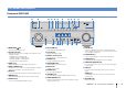
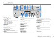
Part names and functions Front panel (HTR-7065) 1 2 3 4 5 6 7 8 9 : AM TUNING A MAIN ZONE B PURE DIRECT ZONE 2 ZONE CONTROL MEMORY INFO PRESET FM INPUT VOLUME SCENE BD DVD YPAO MIC PHONES TV TONE CONTROL NET PROGRAM RADIO STRAIGHT SILENT CINEMA C 1 MAIN ZONE z key Turns on/off (standby) the unit. 2 Standby indicator Lights up when the unit is in standby mode under any of the following conditions. • HDMI Control is enabled (p.96) • Standby Through is enabled (p.
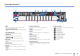
Front panel (HTR-6065) 1 23 MAIN ZONE 4 56 7 8 9 : A B C YPAO MIC PURE DIRECT ZONE 2 ZONE CONTROL MEMORY INFO PRESET FM AM TUNING VOLUME SCENE BD DVD PHONES INPUT TV TONE CONTROL NET PROGRAM RADIO STRAIGHT SILENT CINEMA D 1 MAIN ZONE z key Turns on/off (standby) the unit. 2 Standby indicator Lights up when the unit is in standby mode under any of the following conditions. • HDMI Control is enabled (p.96) • Standby Through is enabled (p.97) • Network Standby is enabled (p.
Front display (indicators) 1 OUT 1 2 3 OUT1/OUT2 (HTR-7065 only) Indicates the HDMI OUT jacks currently outputting an HDMI signal OUT (HTR-6065 only) Lights up when HDMI signals are being output. 2 CINEMA DSP Lights up when CINEMA DSP (p.48) is working. CINEMA DSP n Lights up when CINEMA DSP 3D (p.50) is working. 3 ENHANCER Lights up when Compressed Music Enhancer (p.52) is working. 4 ADAPTIVE DRC Lights up when Adaptive DRC (p.79) is working. 7 89 SLEEP ZONE 2 : VOL.
Rear panel (HTR-7065) 1 2 DC OUT 5V 0.5A 3 NETWORK HDMI 1 HDMI OUT (NET) 1 5 4 HDMI 2 (BD/DVD) HDMI 3 6 HDMI 4 7 HDMI 5 2 ARC SPEAKERS ANTENNA (RADIO) COMPONENT VIDEO AM FRONT COMPONENT VIDEO CENTER SURROUND BACK/BI AMP SURROUND ZONE 2/PRESENCE REMOTE FM PR IN PR SINGLE OUT PB PB VIDEO VIDEO Y Y MONITOR OUT EXTRA SP 12V 0.
Rear panel (HTR-6065) 1 2 DC OUT 5V 0.5A 3 NETWORK HDMI 1 HDMI OUT (NET) 5 4 HDMI 2 (BD/DVD) HDMI 3 6 HDMI 4 7 HDMI 5 ARC SPEAKERS ANTENNA (RADIO) COMPONENT VIDEO AM FRONT COMPONENT VIDEO CENTER SURROUND SURROUND BACK/BI-AMP ZONE 2/PRESENCE REMOTE FM PR EXTRA SP IN PR SINGLE OUT PB PB VIDEO VIDEO Y Y MONITOR OUT 12V 0.
Remote control 1 Remote control signal transmitter 1 Transmits infrared signals. 2 SOURCE z key 2 RECEIVER SOURCE Turns on/off an external device. SOURCE key HDMI 1 2 3 4 5 3 Sets the remote control to operate external devices (p.109). This key lights up in green after pressed. V-AUX RECEIVER key AV 1 2 3 4 Sets the remote control to operate the unit (p.109). This key lights up in orange after pressed.
PREPARATIONS General setup procedure 1 Placing speakers (p.15) Select the speaker layout for the number of speakers that you are using and place them in your room. 2 Connecting speakers (p.19) Connect the speakers to the unit. 3 Connecting a TV (p.23) Connect a TV to the unit. 4 Connecting playback devices (p.28) Connect video devices (such as BD/DVD players) and audio devices (such as CD players) to the unit. 5 Connecting the FM/AM antennas (p.32) Connect the supplied FM/AM antennas to the unit.
1 Speaker placement 2 3 4 5 6 7 8 9 10 1 Placing speakers Select the speaker layout for the number of speakers that you are using and place the speakers and subwoofer (with built-in amplifier) in your room. This section describes the representative speaker layout examples. Caution • Under its default settings, the unit is configured for 8-ohm speakers. When connecting 6-ohm speakers, set the unit’s speaker impedance to “6 Ω MIN”. In this case, you can also use 4-ohm speakers as the front speakers.
1 Speaker placement 2 3 4 5 6 7 8 9 10 7.1+2-channel system 7.1-channel system (using surround back speakers) Q W 1 9 1 2 3 4 5 6 9 9 2 3 4 5 6 7 7 • The surround back speakers and presence speakers do not produce sounds simultaneously. The unit automatically changes the speakers to be used, depending on the selected CINEMA DSP (p.48). 7.1-channel system (using presence speakers) Q W 1 9 4 6.
1 Speaker placement 2 3 4 5 6 7 8 9 10 5.1-channel system 3.1-channel system 1 9 2 1 3 9 4 3 5 4.1-channel system 2.
1 Speaker placement 2 3 4 5 6 7 8 9 10 ■ Setting the speaker impedance Under its default settings, the unit is configured for 8-ohm speakers. When connecting 6-ohm speakers, set the speaker impedance to “6 Ω MIN”. In this case, you can also use 4-ohm speakers as the front speakers. 1 Before connecting speakers, connect the power cable to an AC wall outlet. 2 While holding down STRAIGHT on the front panel, press MAIN ZONE z. MAIN ZONE z STRAIGHT 3 Check that “SP IMP.
1 2 Speaker connections 3 4 5 6 7 8 9 10 2 Connecting speakers Connect the speakers placed in your room to the unit. The following diagrams provide connections for 7.1+2-, 7.1-, and 6.1-channel systems as examples. For other systems, connect speakers while referring to the connection diagram for the 6.1-channel system. 7.1+2-channel system 7.
1 2 Speaker connections 3 4 5 6 7 8 9 10 7.1-channel system (using presence speakers) The unit (rear) The unit (rear) SPEAKERS FRONT ■ Connecting speaker cables 6.1-channel system CENTER SPEAKERS SURROUND BACK/BI AMP SURROUND ZONE 2/PRESENCE FRONT CENTER SURROUND BACK/BI AMP SURROUND SINGLE EXTRA SP SINGLE ZONE 2/PRESENCE SINGLE EXTRA SP CENTER SINGLE Speaker cables have two wires.
1 2 Speaker connections 3 4 5 6 7 8 9 10 Push-type speaker terminals (HTR-6065 only) a Remove approximately 10 mm (3/8”) of insulation from the ends of the speaker cable, and twist the bare wires of the cable firmly together. b Press down the tab. c Insert the bare wires of the cable into the hole in the terminal. d Release the tab. a b c When using front speakers that support bi-amp connections, connect them to the FRONT jacks and SURROUND BACK/BI-AMP jacks.
Input/output jacks and cables ■ Video/audio jacks ■ Video jacks ■ Audio jacks ❑ HDMI jacks ❑ COMPONENT VIDEO jacks ❑ OPTICAL jacks Transmit digital video and digital sound through a single jack. Use an HDMI cable. Transmit video signals separated into three components: luminance (Y), chrominance blue (PB), and chrominance red (PR). Use a component video cable with three plugs. Transmit digital audio signals. Use a digital optical cable. Remove the tip protector (if available) before using the cable.
1 2 3 TV connection 4 5 6 7 8 9 10 3 Connecting a TV Connect a TV to the unit so that video input to the unit can be output to the TV. You can also enjoy playback of TV audio on the unit. ■ Connection Method 1 (HDMI Control/ARC-compatible TV) Connect the TV to the unit with an HDMI cable. The connection method varies depending on the functions and video input jacks available on your TV. Refer to the instruction manual of the TV and choose a connection method.
1 2 3 TV connection 4 5 6 7 8 9 10 ❑ Necessary settings To use HDMI Control and ARC, you need to configure the following settings. 3 Configure the settings for HDMI Control. For details on settings and operating your TV, refer to the instruction manual for the TV. a Enable HDMI Control on the TV and playback devices (such as HDMI Control-compatible BD/DVD player).
1 2 3 TV connection 4 5 6 7 8 9 10 ■ Connection Method 2 (HDMI Control-compatible TV) ❑ Necessary settings Connect the TV to the unit with an HDMI cable and a digital optical cable. To use HDMI Control, you need to configure the following settings. For details on settings and operating your TV, refer to the instruction manual for the TV. • The following explanation is based on the assumption that you have not changed the “HDMI” parameters (p.96) in the “Setup” menu.
1 2 3 TV connection 4 5 6 7 8 9 10 3 Configure the settings for HDMI Control. a Enable HDMI Control on the TV and playback devices (such as a HDMI Control-compatible BD/DVD player). b Turn off the TV’s main power and then turn off the unit and playback devices. c Turn on the unit and playback devices and then turn on the TV. ■ Connection Method 3 (TV with HDMI input jacks) Connect the TV to the unit with an HDMI cable and a digital optical cable.
1 2 3 TV connection 4 5 6 7 8 9 10 ■ Connection Method 4 (TV without HDMI input jacks) When connecting any video device to the AV 1–2 (COMPONENT VIDEO) jacks of the unit, connect the TV to the MONITOR OUT (COMPONENT VIDEO) jacks. When connecting any video device to the AV 3–6 (VIDEO) jacks or the front VIDEO jack of the unit, connect the TV to the MONITOR OUT (VIDEO) jack. If you select “AV 4” as the input source by pressing AV 4 or SCENE(TV), the TV audio will be played back on the unit.
1 2 3 4 Playback device connections 5 6 7 8 9 10 4 Connecting playback devices The unit is equipped with a variety of input jacks including HDMI input jacks to allow you to connect different types of playback devices. For information on how to connect an iPod or a USB storage device, see the following pages. – Connecting an iPod (p.58) ■ Component video connection Connect a video device to the unit with a component video cable and an audio cable (digital optical or digital coaxial).
1 2 3 4 Playback device connections 5 6 7 8 9 10 ■ Composite video connection ■ Changing the combination of video/audio input jacks Connect a video device to the unit with a video pin cable and an audio cable (digital coaxial, digital optical, or stereo pin cable). Choose a set of input jacks (on the unit) depending on the audio output jacks available on your video device.
1 2 3 4 Playback device connections 5 6 7 8 9 10 • The following operation is available only when your TV is connected to the unit via HDMI. 1 After connecting external devices (such as a TV and playback devices) and power cable of the unit, turn on the unit. 2 Press AV 2 to select “AV 2” (video input jack to be used) as the input source. 5 6 7 Use the cursor keys to select “Audio In” and press ENTER. 8 Press ON SCREEN. Use the cursor keys to select “AV5” (audio input jack to be used).
1 2 3 4 Playback device connections 5 6 7 8 9 10 Connecting audio devices (such as CD players) Connecting to the jacks on the front panel Connect audio devices such as CD players and MD players to the unit. Depending on the audio output jacks available on your audio device, choose one of the following connections. Use the VIDEO AUX jack to temporarily connect devices such as game consoles and camcorders to the unit.
1 2 3 4 5 FM/AM antenna connections 6 Network connections 7 8 9 10 5 Connecting the FM/AM antennas Connect the supplied FM/AM antennas to the unit. Fix the end of the FM antenna to a wall, and place the AM antenna on a flat surface. 6 Connecting to a network Connect the unit to your router with a commercially-available STP network cable (CAT-5 or higher straight cable). You can enjoy Internet radio or music files stored on media servers, such as PCs and Network Attached Storage (NAS), on the unit.
1 2 3 4 5 6 7 Other connections 8 9 10 7 Connecting other devices 4 SUBWOOFER1–2 jacks For connecting a subwoofer with built-in amplifier. When 2 subwoofers are connected, the same sound is output from them. 5 CENTER jack Connecting an external power amplifier (HTR-7065 only) When connecting an external power amplifier (pre-main amplifier) to enhance speaker output, connect the input jacks of the power amplifier to the PRE OUT jacks of the unit.
1 2 3 4 5 6 7 Other connections 8 9 10 Connecting a device that supports SCENE link playback (remote connection) If you have a Yamaha product that supports SCENE control signal transmission, you can operate it remotely by connecting it to the REMOTE OUT jack, using a monaural mini-jack cable, and linking with the SCENE function (p.46).
1 2 3 4 5 6 7 8 Power cable connection 9 10 8 Connecting the power cable After all the connections are complete, plug in the power cable. The unit (rear) To an AC wall outlet DMI 5 SPEAKERS CENTER SURROUND BACK/BI AMP SURROUND ZONE 2/PRESENCE SINGLE EXTRA SP SINGLE NE 2 OUT FRONT SURROUND SUR.
1 2 3 4 5 6 7 8 9 Language setting 10 RECEIVER SOURCE RECEIVER z 9 Selecting an on-screen menu language HDMI 1 2 3 4 5 Select the desired on-screen menu language from English (default), Japanese, French, German, Spanish, Russian and Chinese. V-AUX AV 1 2 3 4 AUDIO 5 6 1 TUNER USB NET MAIN PARTY ZONE 2 2 HDMI OUT SCENE BD DVD TV NET PROGRAM MUTE TOP MENU RADIO VOLUME POP-UP/MENU ON SCREEN ON SCREEN 1 2 Press RECEIVER z to turn on the unit. 3 4 Press ON SCREEN.
1 2 3 4 5 6 7 8 9 10 Automatic speaker setup RECEIVER SOURCE RECEIVER z 10 Optimizing the speaker settings automatically (YPAO) HDMI 1 2 3 4 5 V-AUX AV 1 2 3 4 AUDIO 5 6 1 TUNER USB NET MAIN PARTY ZONE 2 2 The Yamaha Parametric room Acoustic Optimizer (YPAO) function detects speaker connections, measures the distances from them to your listening position(s), and then automatically optimizes the speaker settings, such as volume balance and acoustic parameters, to suit your room.
1 2 3 4 5 6 7 8 9 10 Automatic speaker setup The following screen appears on the TV. (HTR-6065) HDMI 1 5 RECEIVER SOURCE 2 3 4 5 (HTR-7065 only) If desired, change the measuring method (multi/single). a Use the cursor keys to select “Multi Position” and press ENTER. V-AUX AV 1 2 3 5 6 1 b Use the cursor keys to select a setting and then press ENTER.
1 2 3 4 5 6 7 8 9 10 Automatic speaker setup RECEIVER SOURCE Single measure Multi measure (5 listening positions) HDMI 1 2 3 4 5 Follow the procedure below for measurement. V-AUX AV 1 2 3 Measuring at one listening position (single measure) 4 AUDIO 5 6 1 TUNER USB NET MAIN PARTY ZONE 2 2 • Do not stand between the speakers and the YPAO microphone during the measurement process (about 3 minutes).
1 2 3 4 5 6 7 8 9 10 Automatic speaker setup RECEIVER SOURCE HDMI 1 2 3 V-AUX AV 2 Use the cursor keys to select “Save/Cancel” and press ENTER. 3 To save the measurement results, use the cursor keys (e/r) to select “SAVE” and press ENTER. 4 5 1 2 3 4 AUDIO 5 6 1 TUNER USB NET MAIN PARTY ZONE 2 2 TV NET When “Multi Position” is set to “Yes”, follow the procedure below for measurement. • Do not stand between the speakers and the YPAO microphone during the measurement process.
1 2 3 4 5 6 7 8 9 10 Automatic speaker setup 3 RECEIVER SOURCE HDMI 1 2 3 4 5 V-AUX AV 1 2 3 5 6 1 TUNER USB NET When you have taken measurements at 8 listening positions, the following screen appears automatically. 4 AUDIO MAIN PARTY ZONE 2 When the measurements at the positions you want to measure are completed, use the cursor keys to select “CANCEL” and press ENTER. 2 HDMI OUT 6 Disconnect the YPAO microphone from the unit.
1 2 3 4 5 6 7 8 9 10 Automatic speaker setup 2 RECEIVER SOURCE HDMI 1 2 3 4 5 Wiring Polarity of each speaker Normal: The speaker cable is connected with the correct polarity (+/-). Reverse: The speaker cable may be connected with the reverse polarity (+/-). Size Size of each speaker (cross-over frequency of the subwoofer) Large: The speaker can reproduce low-frequency signals effectively. Small: The speaker cannot reproduce low-frequency signals effectively.
1 2 3 4 5 6 7 8 9 10 Automatic speaker setup Error messages If any error message is displayed during the measurement, resolve the problem and perform YPAO again. Error message Cause E-1: No Front SP Front speakers are not detected. E-2: No Sur. SP One of the surround speakers cannot be detected. E-3: No F.PRNS SP One of the presence speakers cannot be detected. E-4: SBR → SBL A surround back speaker is connected to the R side only.
1 2 3 4 5 6 7 8 9 10 Automatic speaker setup Warning messages If a warning message is displayed after the measurement, you can still save the measurement results by following on-screen instructions. However, we recommend you perform YPAO again in order to use the unit with the optimal speaker settings. Warning message Cause Remedy W-1: Out of Phase A speaker cable may be connected with the reverse polarity (+/-). Select “Wiring” in “Result” (p.
PLAYBACK RECEIVER SOURCE HDMI 1 2 3 4 5 V-AUX AV 1 2 3 4 Input selection keys Basic playback procedure AUDIO 5 6 1 TUNER USB NET MAIN PARTY ZONE 2 2 1 Turn on the external devices (such as a TV or BD/DVD player) connected to the unit. Selecting an HDMI output jack (HTR-7065 only) 2 Use the input selection keys to select an input source. 1 3 Start playback on the external device or select a radio station.
SOURCE RECEIVER SOURCE Selecting the input source and favorite settings with one touch (SCENE) HDMI 1 2 3 4 5 V-AUX AV 1 2 3 5 6 1 4 TUNER USB NET Input selection keys AUDIO MAIN PARTY ZONE 2 The SCENE function allows you to select the assigned input source, sound program, Compressed Music Enhancer on/off, and HDMI output jack (HTR-7065 only) with just one touch.
Selecting the sound mode RECEIVER SOURCE HDMI 1 2 3 4 5 The unit is equipped with a variety of sound programs and surround decoders that allow you to enjoy playback sources with your favorite sound mode (such as sound field effect or stereo playback). V-AUX AV 1 2 3 4 5 6 1 AUDIO TUNER MAIN USB 2 NET PARTY ZONE 2 Selecting a sound program suitable for movies (p.48) HDMI OUT Press MOVIE repeatedly.
Enjoying sound field effects (CINEMA DSP) The unit is equipped with a variety of sound programs that utilize Yamaha’s original DSP technology (CINEMA DSP). It allows you to easily create sound fields like actual movie theaters or concert halls in your room. Drama This program features stable reverberations that match a wide range of movie genres, from serious dramas to musicals and comedies. The reverberations are modest, but suitably stereophonic.
■ Sound programs suitable for music/stereo playback (MUSIC) The following sound programs are optimized for listening to music sources. You can also select stereo playback. ❑ CLASSICAL Hall in Munich This program simulates a Munich concert hall with approximately 2,500 seats that uses stylish wood for the interior finishing. Fine, beautiful reverberations spread richly, creating a calming atmosphere. The listener’s virtual seat is at the center left of the arena.
RECEIVER SOURCE HDMI 1 2 3 ■ Enjoying stereoscopic sound fields (CINEMA DSP 3D) Enjoying unprocessed playback CINEMA DSP 3D creates a natural stereoscopic sound field in your room. ■ Playing back in original channels (straight decode) 4 5 V-AUX You can play back input sources without any sound field effect processing. AV 1 2 3 5 6 1 4 TUNER USB NET AUDIO MAIN PARTY ZONE 2 2 CINEMA DSP 3D functions when both of the following conditions are met.
■ Playing back 2-channel sources in multichannel (surround decoder) RECEIVER SOURCE HDMI 1 2 3 4 5 The surround decoder enables unprocessed multichannel playback from 2-channel sources. When a multichannel source is input, it works the same way as the straight decode mode.
Enjoying compressed music with enhanced sound (Compressed Music Enhancer) RECEIVER SOURCE HDMI 1 2 3 4 5 V-AUX AV 1 2 3 5 6 1 4 TUNER USB NET AUDIO MAIN PARTY ZONE 2 2 Compressed Music Enhancer adds depth and breadth to the sound, allowing you to enjoy a dynamic sound close to the original sound before it was compressed. This function can be used along with any other sound modes.
Listening to FM/AM radio RECEIVER SOURCE HDMI 1 2 3 4 5 You can tune into a radio station by specifying its frequency or selecting from registered radio stations. V-AUX AV 1 2 3 5 6 1 TUNER USB NET 4 AUDIO MAIN PARTY ZONE 2 2 HDMI OUT • The radio frequencies differ depending on the country or region where the unit is being used. The explanation of this section uses a display with frequencies used in a Europe model.
Registering favorite radio stations (presets) RECEIVER SOURCE HDMI 1 2 3 You can register up to 40 radio stations as presets. Once you have registered stations, you can easily tune into them by selecting their preset numbers. 4 5 V-AUX AV 1 2 3 4 ■ Selecting a preset station Tune into a registered radio station by selecting its preset number. 1 Press TUNER to select “TUNER” as the input source. 2 Press PRESET repeatedly to select the desired radio station.
Radio Data System tuning RECEIVER SOURCE • “Program Service”, “Program Type”, “Radio Text”, and “Clock Time” are not displayed if the radio station does not provide the Radio Data System service. HDMI 1 2 3 (Europe model only) 4 5 Radio Data System is a data transmission system used by FM stations in many countries.
Operating the radio on the TV RECEIVER SOURCE Menu HDMI 1 2 3 You can view the radio information or select a radio station on the TV. 4 5 V-AUX Submenu Function FM (Europe model only) Switches to FM/AM. AM AV 1 2 3 5 6 1 4 1 AUDIO TUNER MAIN USB 2 TUNER NET PARTY ZONE 2 Press TUNER to select “TUNER” as the input source. Manual Tuning The playback screen is displayed on the TV.
■ Browse screen RECEIVER SOURCE HDMI 1 2 3 4 5 1 V-AUX AV 1 2 3 4 5 6 1 TUNER USB NET AUDIO MAIN PARTY ZONE 2 3 2 HDMI OUT 2 SCENE BD DVD TV NET RADIO 1 Preset station list PROGRAM MUTE TOP MENU VOLUME Displays the list of preset stations. Use the cursor keys to select a preset station and press ENTER to tune into it.
Playing back iPod music You can play back iPod music on the unit using a USB cable supplied with the iPod. Connecting an iPod Connect your iPod to the unit with the USB cable supplied with the iPod. • Some features may not be compatible, depending on the model or software version of the iPod. • To play back iPod videos on the unit, an Apple Composite AV Cable (not supplied) is required.
Playback of iPod content RECEIVER SOURCE ■ Browse screen HDMI 1 2 3 V-AUX AV 1 2 3 5 6 1 1 2 3 Follow the procedure below to operate the iPod contents and start playback. 4 5 You can control the iPod with the menu displayed on the TV screen. 4 AUDIO TUNER MAIN USB 2 USB NET PARTY ZONE 2 1 5 Press USB to select “USB” as the input source. The browse screen is displayed on the TV.
■ Playback screen RECEIVER SOURCE HDMI 1 2 3 1 2 4 5 V-AUX AV 1 2 3 ■ Operating the iPod itself or remote control (simple play) 1 4 5 6 TUNER MAIN 1 USB 3 2 NET PARTY ZONE 2 To display the TV menu screen, press MODE again. HDMI OUT 2 SCENE BD DVD TV NET RADIO 1 Status indicators PROGRAM MUTE TOP MENU VOLUME Display the current repeat/shuffle settings (p.61) and playback status (such as play/pause).
■ Repeat/shuffle settings RECEIVER SOURCE You can configure the repeat/shuffle settings of your iPod. HDMI 1 2 3 4 5 V-AUX AV 1 2 3 5 6 1 • During simple play, configure the repeat/shuffle settings directly on your iPod or press MODE to display the TV menu screen and then follow the procedure below. 4 AUDIO TUNER MAIN USB 2 NET PARTY ZONE 2 HDMI OUT 1 When “USB” is selected as the input source, press OPTION.
Playing back music stored on a USB storage device RECEIVER SOURCE HDMI 1 2 3 4 5 You can play back music files stored on a USB storage device on the unit. Refer to the instruction manuals for the USB storage device for more information. V-AUX AV 1 2 3 4 AUDIO 5 6 1 TUNER USB NET MAIN PARTY ZONE 2 2 USB • If the USB storage device contains many files, it may take time to load the them. In this case, “Loading...” appears in the front display.
2 RECEIVER SOURCE HDMI 1 2 3 4 5 AV 2 3 5 6 1 TUNER USB NET ■ Browse screen 1 2 3 If a song is selected, playback starts and the playback screen is displayed. V-AUX 1 Use the cursor keys to select an item and press ENTER.
■ Playback screen RECEIVER SOURCE HDMI 1 2 3 V-AUX AV 1 2 3 5 6 1 You can configure the repeat/shuffle settings for playback of USB storage device contents. 1 2 4 5 ■ Repeat/shuffle settings 4 AUDIO TUNER MAIN USB 3 2 1 When “USB” is selected as the input source, press OPTION. 2 Use the cursor keys to select “Shuffle” (Shuffle) or “Repeat” (Repeat) and press ENTER.
Playing back music stored on media servers (PCs/NAS) RECEIVER SOURCE HDMI 1 2 3 4 5 1 2 3 5 6 1 Playback of PC music contents You can play back music files stored on your PC or DLNA-compatible NAS on the unit. V-AUX AV 4 Follow the procedure below to operate the PC music contents and start playback. AUDIO TUNER MAIN USB 2 HDMI OUT • To use this function, the unit and your PC must be connected to the same router (p.32).
3 RECEIVER SOURCE HDMI 1 2 3 4 5 AV 2 3 5 6 1 TUNER USB NET ■ Browse screen 1 2 3 If a song is selected, playback starts and the playback screen is displayed. V-AUX 1 Use the cursor keys to select an item and press ENTER.
■ Playback screen RECEIVER SOURCE HDMI 1 2 3 V-AUX AV 1 2 3 5 6 1 You can configure the repeat/shuffle settings for the playback of PC music content. 1 2 4 5 ■ Repeat/shuffle settings 4 AUDIO TUNER MAIN USB 3 2 1 When “SERVER” is selected as the input source, press OPTION. 2 Use the cursor keys to select “Shuffle” (Shuffle) or “Repeat” (Repeat) and press ENTER.
Listening to Internet radio RECEIVER SOURCE HDMI 1 2 3 4 5 You can listen to Internet radio stations from all over the world. V-AUX You can control the Internet radio with the menu displayed on the TV screen. AV 1 2 3 4 AUDIO 5 6 1 TUNER USB NET MAIN PARTY ZONE 2 2 TV NET Press NET repeatedly to select “NET RADIO” as the input source. The browse screen is displayed on the TV. NET HDMI OUT • To use this function, the unit must be connected to the Internet (p.32).
■ Browse screen RECEIVER SOURCE HDMI 1 2 3 1 2 3 4 5 V-AUX AV 1 2 3 5 6 1 TUNER USB NET ■ Playback screen 4 1 2 AUDIO MAIN PARTY ZONE 2 HDMI OUT 4 SCENE BD DVD TV NET PROGRAM MUTE TOP MENU 3 5 2 RADIO VOLUME RETURN DISPLAY BAND 2 List name 2 Playback information Displays the station name, album name, song title, and elapsed time. Displays the list of Internet radio content. Use the cursor keys to select an item and press ENTER to confirm the selection.
Playing back iTunes/iPod music via a network (AirPlay) The AirPlay function allows you to play back iTunes/iPod music on the unit via network. Playback of iTunes/iPod music contents Follow the procedure below to play back iTunes/iPod music contents on the unit. iTunes PC 1 Router The unit Starts playback on iTunes or iPod Turn on the unit, and start iTunes on the PC or display the playback screen on the iPod. If the iTunes/iPod recognizes the unit, the AirPlay icon ( ) appears.
Menu RECEIVER SOURCE • The playback screen is available only when your TV is connected to the unit via HDMI. HDMI 1 2 3 4 5 V-AUX Play Control AV 1 2 3 5 6 1 4 • You can turn on the unit automatically when starting playback on iTunes or iPod by setting “Network Standby” (p.98) in the “Setup” menu to “On”. AUDIO TUNER MAIN USB 2 • You can edit the network name (the unit’s name on the network) displayed on iTunes/iPod in “Network Name” (p.99) in the “Setup” menu.
Playing back music in multiple rooms (multi-zone) The multi-zone function allows you to play back different input sources in the room where the unit is installed (main zone) and in another room (Zone2). For example, while you are watching TV in the living room (main zone), another person can listen to radio in the study room (Zone2). Preparing Zone2 Connect the device that will be used in Zone2 to the unit.
■ Using the unit’s internal amplifier ■ Using an external amplifier Connect the speakers placed in Zone2 to the unit with speaker cables. Connect the external amplifier (with volume control) placed in Zone2 to the unit with a stereo pin cable. To utilize the EXTRA SP terminals for Zone2 speakers, set “Power Amp Assign” (p.91) in the “Setup” menu to “7ch +1ZONE” after connecting the power cable to an AC wall outlet.
■ Operating the unit from Zone2 (remote connection) Remote connections between Yamaha products You can operate the unit and external devices from Zone2 using the supplied remote control if you connect an infrared signal receiver/emitter to the unit’s REMOTE IN/OUT jacks. An infrared signal transmitter is not required if you are using Yamaha products that support remote connections, as the unit does.
RECEIVER SOURCE RECEIVER z Controlling Zone2 4 HDMI 1 2 3 4 5 V-AUX AV 1 2 3 4 5 6 1 AUDIO TUNER MAIN USB 2 NET PARTY ZONE 2 AV 5–6 AUDIO 1–2 TUNER USB NET 1 2 HDMI OUT MAIN/ZONE2 TV NET PROGRAM MUTE TOP MENU RADIO VOLUME MUTE VOLUME Set MAIN/ZONE2 to “ZONE2”. Refer to the instruction manual for the external device. Press RECEIVER z. For details on the following operations, see the corresponding pages. Each time you press the key, Zone2 output is enabled or disabled.
■ Enjoying the same source in multiple rooms (party mode) RECEIVER SOURCE HDMI 1 2 3 4 (HTR-7065 only) 5 V-AUX AV 1 2 3 4 AUDIO 5 6 1 TUNER USB NET MAIN PARTY ZONE 2 2 HDMI OUT PARTY The party mode allows you to play back in Zone2 the same music that is being played back in the main zone. During the party mode, stereo playback is automatically selected for all zones. Utilize this function when you want to use main zone music as background music for a house party.
Viewing the current status RECEIVER SOURCE HDMI 1 2 3 4 5 V-AUX AV 1 2 3 4 Switching information on the front display Viewing the status information on the TV 1 1 AUDIO 5 6 1 TUNER USB NET MAIN PARTY ZONE 2 2 HDMI OUT Press INFO. Each time you press the key, the displayed item changes. Press DISPLAY. The following information is displayed on the TV. SCENE BD DVD TV NET RADIO Audio Decoder PROGRAM MUTE Compressed Music Enhancer status VOL.
Configuring playback settings for different playback sources (Option menu) You can configure separate playback settings for different playback sources. This menu is available on the front panel (or on the TV screen), allowing you to easily configure settings during playback. 1 Press OPTION. Option menu items • Available items vary depending on the selected input source. • Text in parentheses denotes indicators on the front display. OPTION Tone Control VOL.
■ Tone Control (Tone Control) ■ CINEMA DSP 3D Mode (CINEMA DSP 3D) Adjusts the high-frequency range (Treble) and low-frequency range (Bass) of sounds. Enables/disables CINEMA DSP 3D (p.50). If this function is set to “On”, CINEMA DSP 3D functions with the selected sound programs (except 2ch Stereo and 7ch Stereo). Choices Treble (Treble), Bass (Bass) Settings Setting range -6.0 dB to Bypass (Bypass) to +6.0 dB, *0.5 dB increments Default Bypass (Bypass) On (On) (default) Enables CINEMA DSP 3D.
■ Extended Surround (EXTD Surround) ❑ Subwoofer Trim (SW.Trim) Selects how to play back 5.1- to 7.1-channel sources when surround back speakers are used. Fine-adjusts the subwoofer volume. Settings Auto (Auto) (default) Automatically selects the most suitable decoder if signals that contain surround back channel signals are input, and reproduces the signals in 6.1- or 7.1-channel. If two surround back speakers are connected, the unit reproduces the 5.1-channel signals in 7.1-channel.
CONFIGURATIONS Configuring input sources (Input menu) 4 Use the cursor keys (q/w) to select an item and press ENTER. You can change the input source settings using the TV screen. 1 2 Press ON SCREEN. Use the cursor keys to select “Input” and press ENTER. • To return to the previous screen during menu operations, press RETURN. 3 5 6 Use the cursor keys (e/r) to select an input source to be configured and press the cursor key (q). Use the cursor keys to select a setting and press ENTER.
■ Rename/Icon Select ■ Audio In Changes the input source name and icon displayed on the front display or TV screen. Combines the video jack of the selected input source with an audio jack of others. For example, use this function in the following cases. Input sources HDMI 1–5, V-AUX, AV 1–6, AUDIO 1–2, USB ■ Setup procedure 1 Use the cursor keys (e/r) to select a template and press the cursor key (w).
■ Volume Interlock Enables/disables volume controls from iTunes/iPod via AirPlay. Configuring the SCENE function (Scene menu) You can change the settings of the SCENE function (p.46) using the TV screen. Input sources AirPlay Settings Off Disables volume controls from iTunes/iPod. Limited (default) Enables volume controls from iTunes/iPod within the limited range (-80 dB to 0 dB and mute). Full Enables volume controls from iTunes/iPod in the full range (-80 dB to +16.5 dB and mute).
4 ■ Load Use the cursor keys (q/w) to select an item and press ENTER. Loads the settings registered for the selected scene. Select “DETAIL” to configure the SCENE link playback setting or view the scene assignments. ❑ Device Control Recalls a selected scene and starts its playback on an external device connected to the unit via HDMI or on a Yamaha product connected to the REMOTE OUT jack. (SCENE link playback) Settings 5 6 Use the cursor keys and ENTER to change the setting.
■ Rename/Icon Select Changes the scene name and icon displayed on the front display or TV screen. ■ Setup procedure 1 2 3 Use the cursor keys (e/r) to select an icon and press the cursor key (w). Configuring sound programs/surround decoders (Sound Program menu) You can change the settings of the sound programs and surround decoders using the TV screen. 1 2 Press ON SCREEN. 3 Use the cursor keys (e/r) to select a sound program to be configured and press the cursor key (q).
4 Use the cursor keys (q/w) to select an item and press ENTER. Sound Program menu items • Available items vary depending on the selected sound program or surround decoder. ■ Settings for sound programs • To return to the previous screen during menu operations, press RETURN. Item Function Decode Type Selects a surround decoder to be used bPLIIx Movie (bPLII in combination with the selected sound Movie), Neo:6 Cinema program. DSP Level Adjusts the sound field effect level.
■ Settings for decoders Item Function Settings Reverb Delay Adjusts the delay between the direct sound and reverberant sound generation. 0 ms to 250 ms Higher to enhance the delay effect, and lower to reduce it. Adjusts the volume of the reverberant sound. 0% to 100% Higher to strengthen the reverberant sound, and lower to weaken it. Reverb Level The following items are available when you set “Decode Type” of “Surround Decoder” to “bPLIIx Music” or “Neo:6 Music”.
Configuring various functions (Setup menu) You can configure the unit’s various function with the menu displayed on the TV screen. 1 2 Press ON SCREEN. 3 Use the cursor keys (e/r) to select a menu. 4 Use the cursor keys (q/w) to select an item and press ENTER. • To return to the previous screen during menu operations, press RETURN. 5 6 Use the cursor keys to select a setting and press ENTER. To exit from the menu, press ON SCREEN. Use the cursor keys to select “Setup” and press ENTER.
Setup menu items Menu Item Function Auto Setup Power Amp Assign Page Automatically optimizes the speaker settings (YPAO). 37 Selects a speaker system. 91 Front Selects the size of the front speakers. 91 Center Selects whether or not a center speaker is connected and its size. 91 Surround Selects whether or not surround speakers are connected and their size. 91 Surround Back Selects whether or not surround back speakers are connected and their size.
Menu Item Function Page IP Address Configures the network parameters (such as IP address). 98 Network Standby Selects whether to enable/disable the function that turns on the unit from other network devices. 98 MAC Address Filter Sets the MAC address filter to limit access to the unit from other network devices. 98 Network Name Edits the network name (the unit’s name on the network) displayed on other network devices.
Speaker (Manual Setup) ❑ Front Selects the size of the front speakers. Configures the speaker settings manually. Settings Large Select this option for large speakers. The front speakers will produce all of the front channel frequency components. Small (default) Select this option for small speakers. The subwoofer will produce front channel low-frequency components (configurable in “Bass Cross Over”). • “Front” is automatically set to “Large” when “Subwoofer” is set to “None”.
❑ Surround Back ❑ Subwoofer Selects whether or not surround back speakers are connected and their sizes. Selects whether or not a subwoofer is connected and its phase. Settings Settings Large x1 Select this option when one large speaker is connected. The surround back speaker will produce all of the surround back channel frequency components. Large x2 Select this option when two large speakers are connected.
■ Distance ■ Manual equalizer adjustment Sets the distance between each speaker and listening position so that sounds from the speakers reach the listening position at the same time. First, select the unit of distance from “Meter” or “Feet”. Choices Front L, Front R, Center, Surround L, Surround R, Surround Back L, Surround Back R, Front Presence L, Front Presence R, Subwoofer 1 2 3 Press ENTER again to enter the edit screen. Use the cursor keys to select a speaker and press ENTER.
Sound ❑ Adjustment Configures the audio output settings. Adjusts the delay between video and audio output manually when “Auto/Manual Select” is set to “Manual”. You can fine-adjust the audio output timing when “Auto/Manual Select” is set to “Auto”. Setting range 0 ms to 500 ms (1 ms increments) Default 0 ms • “Offset” shows the difference between automatic adjustment and fine adjustment. ■ Dynamic Range ■ Lipsync Adjusts the delay between video and audio output.
■ Initial Volume Video Sets the initial volume when the receiver is turned on. Configures the video output settings. Settings Off (default) Sets the level to the volume level of the unit when it last entered standby mode. On Sets at Mute or the specified volume level (-80 dB to +16.5 dB, 0.5 dB increments). (This setting works only when the initial volume is set lower than “Max Volume”.
❑ Aspect HDMI Selects an aspect ratio to output HDMI video signals when “Video Mode” is set to “Processing”. Configures the HDMI settings. Settings Through (default) Does not convert the aspect ratio. 16:9 Normal Outputs 4:3 video signals to a 16:9 TV with black bands on either side of the screen. • This setting functions only when 480i/576i or 480p/576p signals are converted into 720p, 1080i, 1080p, or 2160p (4K) signals. ■ HDMI Control Enables/disables HDMI Control (p.124).
❑ ARC Enables/disables ARC (p.23) when “HDMI Control” is set to “On”. ❑ HDMI OUT1, HDMI OUT2 (HTR-7065 only) HDMI OUT (HTR-6065 only) Enables/disables the audio output from a TV connected to the HDMI OUT jack. Settings Off Disables ARC. On (default) Enables ARC. • You do not need to change this setting normally.
Network Configures the network settings. 6 7 To save the changes, use the cursor keys to select “OK” and press ENTER. To exit from the menu, press ON SCREEN. ■ Network Standby Selects whether the unit can be turned on from other network devices (network standby). Settings Off (default) Disables the network standby function. On Enables the network standby function. (The unit consumes approximately 2 W of power.
■ Network Name Multi Zone Edits the network name (the unit’s name on the network) displayed on other network devices. Configures the multi zone settings. ■ Procedure 1 2 Press ENTER to enter the name edit screen. Use the cursor keys and ENTER to rename and select “ENTER” to confirm the entry. ■ Main Zone Set Configures the main zone setting. ❑ Zone Rename Changes the zone name (for main zone) displayed on the front display or TV screen. • To clear the entry, select “CLEAR”.
■ Zone2 Set Function Configures the Zone2 settings. Configures the functions that make the unit easier to use. ❑ Max Volume Sets the Zone2 maximum volume to prevent excessive loudness. Setting range -30.0 dB to +15.0 dB (5.0 dB increments), +16.5 dB Default +16.5 dB • This setting is available only when “Power Amp Assign” (p.91) is set to “7ch +1ZONE”. ❑ Initial Volume Sets the Zone2 initial volume for when the unit is turned on.
❑ Wall Paper Manual Selects the image to be used as wallpaper on the TV. Switches the output level for electronic signal transmission manually when “Trigger Mode” is set to “Manual”. This setting can also be used to confirm proper function of the external device connected via the TRIGGER OUT jack. Settings Picture 1 (default), Picture 2, Picture 3 Displays the selected image on the TV screen when there is no video signal. Gray Displays a gray background on the TV screen when there is no video signal.
■ Memory Guard ECO Prevents accidental changes to the settings. Configures the power supply settings. Settings Off (default) Does not protect the settings. On Protects the settings until “Off” is selected. • When “Memory Guard” is set to “On”, the lock icon (o) is displayed on the menu screen. Icon ■ Auto Power Down Sets the amount of time for the auto-standby function. If you do not operate the unit for the specified time, the unit will automatically go into standby mode.
Language Select an on-screen menu language. Viewing information about the unit (Information menu) You can view information about the unit using the TV screen. 1 2 Press ON SCREEN. 3 Use the cursor keys (e/r) to select an information type. 4 To exit from the menu, press ON SCREEN. Use the cursor keys to select “Information” and press ENTER.
■ Network Types of information Displays the network information on the unit. ■ Audio Signal IP Address IP address Displays information about the current audio signal. Subnet Mask Subnet mask Default Gateway The IP address of the default gateway DNS Server (P) The IP address of the primary DNS server Format Audio format of the input signal Channel The number of source channels in the input signal (front/surround/LFE) For example, “5.1 (3/2/0.1)” means 5.
ADVANCED SETUP menu items Configuring the system settings (ADVANCED SETUP menu) Item Configure the system settings of the unit while viewing the front display. 1 2 Set the unit to standby mode. While holding down STRAIGHT on the front panel, press MAIN ZONE z. MAIN ZONE z Function Page SP IMP. Changes the speaker impedance setting. 105 REMOTE ID Selects the unit’s remote control ID. 106 TV FORMAT Switches the video signal type. 106 MON.CHK Removes the limitation on HDMI video output.
Selecting the remote control ID (REMOTE ID) Removing the limitation on HDMI video output (MON.CHK) REMOTE ID ID1 Change the unit’s remote control ID so that it matches the remote control’s ID (default: ID1). When using multiple Yamaha AV receivers, you can set each remote control with a unique remote control ID for its corresponding receiver. Settings ID1 (default), ID2 ■ Changing the remote control ID of the remote control Perform each of the following steps within 1 minute.
Updating the firmware (UPDATE) UPDATE USB New firmware that provides additional features or product improvements will be released as needed. Updates can be downloaded from our website. If the unit is connected to the Internet, you can download the firmware via the network. For details, refer to the information supplied with updates. ■ Firmware update procedure Do not perform this procedure unless firmware update is necessary.
SOURCE RECEIVER SOURCE Controlling external devices with the remote control HDMI 1 2 3 4 5 You can use the unit’s remote control to operate external devices (such as BD/DVD players) if you have registered the remote control code of the external device. V-AUX AV 1 2 3 4 AUDIO 5 6 1 TUNER USB NET MAIN PARTY ZONE 2 2 TV NET PROGRAM MUTE Press TV z. Use the numeric keys to enter the 4-digit remote control code.
RECEIVER SOURCE HDMI 1 2 3 4 5 SOURCE z SOURCE RECEIVER V-AUX AV 1 2 3 4 Input selection keys AUDIO 5 6 1 TUNER USB NET MAIN PARTY ZONE 2 2 HDMI OUT Registering the remote control codes for playback devices You can use the unit’s remote control to operate playback devices if you have registered their remote control codes.
SOURCE RECEIVER SOURCE Resetting remote control codes RECEIVER HDMI 1 2 3 You can reset a remote control code registered to each input selection key. 4 5 V-AUX AV 1 2 3 4 Input selection keys AUDIO 5 6 TUNER MAIN 1 USB 2 1 SOURCE blinks twice. NET PARTY ZONE 2 HDMI OUT Perform each of the following steps within 1 minute. Otherwise, the setting will be canceled. If this happens, repeat from Step 1.
Updating the unit’s firmware RECEIVER SOURCE HDMI 1 2 3 4 5 New firmware that provides additional features or product improvements will be released as needed. If the unit is connected to the Internet, you can download the firmware via the network and update it. V-AUX AV 1 2 3 4 AUDIO 5 6 1 TUNER USB NET MAIN PARTY ZONE 2 2 HDMI OUT Note RADIO • Do not operate the unit or disconnect the power cable or network cable during firmware update.
APPENDIX Frequently asked questions The new speaker system does not provide an ideal sound balance... I want to turn off the on-screen messages displayed during operations... If you have changed speakers or have a new speaker system, use “Auto Setup” to optimize the speaker settings again (p.37). If you want to adjust the speaker settings manually, use “Manual Setup” in the “Setup” menu (p.91).
Troubleshooting Refer to the table below when the unit does not function properly. If the problem you are experiencing is not listed below or if the instructions below do not help, turn off the unit, disconnect the power cable, and contact the nearest authorized Yamaha dealer or service center. First, check the following: a The power cables of the unit, TV and playback devices (such as BD/DVD players) are connected to AC wall outlets securely.
Audio Problem No sound. The volume cannot be increased. Cause Select an appropriate input source with the input selection keys. Signals that the unit cannot reproduce are being input. Some digital audio formats cannot be played back on the unit. To check the audio format of the input signal, use “Audio Signal” in the “Information” menu (p.104). The cable connecting the unit and playback device is defective. If there is no problem with the connection, replace with another cable.
Problem No sound from the TV (when HDMI Control is used). Only the front speakers work on multichannel audio. Cause Remedy The TV is set to output audio from the TV speakers. Change the audio output setting on your TV so that the TV audio is output from the speakers connected to the unit. (If the TV is connected to the unit with an audio cable) The TV audio input setting does not match the actual connection. Use “TV Audio Input” in the “Setup” menu to select the correct audio input jack (p.96).
FM/AM radio Problem Cause There is multi-path interference. Remedy Adjust the FM antenna height or orientation, or place it in a different location. Set “FM Mode” in the “Option” menu to “Mono” to select monaural FM radio reception (p.80). FM radio reception is weak or noisy. Your area is too far from the FM station transmitter. Use an outdoor FM antenna. We recommend using a sensitive multi-element antenna. AM radio reception is weak or noisy.
Problem Cause Remedy The files in the PC cannot be viewed or played back. The files are not supported by the unit or the media server. Use the file format supported by both the unit and the media server. For information about the file formats supported by the unit, see “Playing back music stored on media servers (PCs/NAS)” (p.65). The selected Internet radio station is currently not available. There may be a network problem at the radio station, or the service may have been stopped.
Error indications on the front display Message Cause Remedy Access denied Access to the PC is denied. Configure the sharing settings and select the unit as a device to which music contents are shared (p.65). The unit cannot access the USB device. Turn off the unit and reconnect your USB device. If the problem persists, try another USB device. The unit cannot access the iPod. Turn off the iPod and turn it on again. Access error Make sure your router and modem are turned on.
Ideal speaker layout Use this diagram as a guide. You do not need to adjust the speaker layout to the following diagram exactly. Q W 0.5 to 1 m (1.6 to 3.3 ft) 0.5 to 1 m (1.6 to 3.3 ft) 1.8 m (5.9 ft) 1 9 1.8 m (5.9 ft) 2 3 9 Turn it slightly inward to reduce wall reflections. Turn it slightly inward to reduce wall reflections.
Glossary Audio information ■ Audio decoding format Dolby Digital Dolby Digital is a compressed digital audio format developed by Dolby Laboratories, Inc. that supports 5.1-channel audio. This technology is used for audio on most DVD discs. Dolby Digital EX Dolby Digital EX creates total 6.1-channel audio from 5.1-channel sources that are recorded with Dolby Digital Surround EX. This decoder adds a surround back sound to the original 5.1-channel sound.
Sampling frequency/Quantization bit Sampling frequency and quantization bits indicate the quantity of information when an analog audio signal is digitized. These values are noted as in the following example: “48 kHz/24-bit”. • Sampling frequency Sampling frequency (the number of times the signal is sampled per second) is called the sampling rate. When the sampling frequency is higher, the range of frequencies that can be played back are wider.
Yamaha technologies CINEMA DSP (Digital Sound Field Processor) Since the Dolby Surround and DTS systems were originally designed for use in movie theaters, their effect is best experienced in a theater that has many speakers designed for acoustic effects. Since home conditions (such as room size, wall material, and number of speakers) can differ so widely, it is inevitable that there are differences in the sound that you hear.
Video signal flow Video signals input from a video device to the unit are output to a TV as shown below. ■ Video conversion table • You can select the resolution and the aspect ratio applied to HDMI-output video processing in “Video Mode” (p.95) in the “Setup” menu. • The unit does not convert 480-line and 576-line video signals interchangeably.
(Example) Information on HDMI HDMI Control HDMI Control HDMI Control HDMI Control allows you to operate external devices via HDMI. If you connect a TV that supports HDMI Control to the unit with an HDMI cable, you can control the unit (such as power and volume) with TV remote control operations. You can also control playback devices (such as HDMI Control-compatible BD/DVD players) connected to the unit with an HDMI cable. For details on connections, see “Connecting a TV” (p.
7 Check that the unit is properly synchronized with the TV by turning off the TV or adjusting the TV volume with the TV remote control. HDMI signal compatibility Audio signals Audio signal type Audio signal format Compatible media (example) 2ch Linear PCM 2ch, 32 to 192 kHz, 16/20/24 bit CD, DVD-Video, DVD-Audio • If the unit is not synchronized to the TV’s power operations, check the priority of the audio output setting on the TV.
Trademarks Manufactured under license from Dolby Laboratories. Dolby, Pro Logic and the double-D symbol are trademarks of Dolby Laboratories. “HDMI,” the “HDMI” logo and “High-Definition Multimedia Interface” are trademarks, or registered trademarks of HDMI Licensing LLC. x.v.Color™ “x.v.Color” is a trademark of Sony Corporation. Manufactured under license under U.S. Patent Nos: 5,956,674; 5,974,380; 6,226,616; 6,487,535; 7,212,872; 7,333,929; 7,392,195; 7,272,567 & other U.S.
Specifications Input jacks Output jacks Remote jacks • Analog Audio • Analog Audio [HTR-7065] • REMOTE IN x 1 Audio x 4 (AV 5–6, AUDIO 1–2) • Digital Audio (Supported frequencies: 32 kHz to 96 kHz) Optical x 2 (AV 1, AV 4) Coaxial x 2 (AV 2–3) • REMOTE OUT x 1 - Speaker Out x 9 (7 ch) (FRONT L/R, CENTER, *1 *2 SURROUND L/R, SURROUND BACK L/R , EXTRA SP L/R ) HDMI *1 Note: Assignment is possible [SURROUND BACK, BI-AMP (FRONT L/R)] • Video Composite x 5 (AV 3–6, VIDEO [Front Panel]) Component x 2
TUNER Audio Section • Analog Tuner • Rated Output Power (2-channel driven) [Europe model] [HTR-7065] FM/AM with Radio Data System x 1 (TUNER) (20 Hz to 20 kHz, 0.09% THD, 8 Ω) [Other models] Front L/R ................................................................. 95 W+95 W FM/AM x 1 (TUNER) (1 kHz, 0.9% THD, 8 Ω) USB Front L/R ............................................................. 110 W+110 W Center..............................................................................
Video Section General • Video Signal Type • Power Supply [U.S.A. model] ................................................................. NTSC [U.S.A. model].................................................AC 120 V, 60 Hz [Other models].................................................................... PAL [Australia model] .............................................AC 240 V, 50 Hz • Video Signal Type (Video Conversion) .....................NTSC/PAL [Europe model] ...............................
Index Symbols ★ key .........................................................13 Lock icon (o) .........................................102 Numerics 2.1-channel system (Speaker placement) ............................17 2ch Stereo (Sound program) ....................49 3.1-channel system (Speaker placement) ............................17 4.1-channel system (Speaker placement) ............................17 4K signal (Video signal resolution) .........125 5.1-channel system (Speaker placement) ...............
Connection (NAS) .....................................32 Connection (Speaker cable) .....................20 Connection (Speaker) ...............................19 Connection (Subwoofer) ...........................21 Connection (Video devices) ......................28 Crossover frequency setting (Subwoofer) ...........................................37 D DC OUT jack .............................................11 Decode Type (Sound Program menu) ......86 Decoder Mode (Input menu) ....................
HDMI OUT1 (Audio Output, Setup menu) .................97 HDMI OUT2 (Audio Output, Setup menu) .................97 HDMI output jack selection .......................45 HDMI video output (ADVANCED SETUP) ..........................106 Headphones ...............................................8 Height Balance (Sound Program menu) ...87 High definition audio ...............................125 High speed HDMI cable ...........................22 I Impedance (Speaker) ...............................15 In.
P PAL (TV FORMAT, ADVANCED SETUP) ....106 Panorama (Sound Program menu) ...........87 Parametric EQ (Speaker, Setup menu) .....93 PARTY (Multizone function) ......................76 Party mode ................................................76 Party Mode Set (Multi Zone, Setup menu) ....................100 PC (Connection) ........................................32 PC (Playback) ...........................................65 PHONES jack ..............................................8 Placement (Speaker) .....
Speaker (Setup menu) ..............................91 Speaker connection ..................................19 Speaker connection (Bi-amp) ...................21 Speaker impedance ..................................15 Speaker Impedance (System, Information menu) ................104 Speaker impedance setting ......................18 Speaker indicator (Front display) ..............10 Speaker placement ...................................15 Spectacle (Sound program) .....................48 Sports (Sound program) .
Y Yamaha Parametric room Acoustic Optimizer (YPAO) ..................................37 YPAO (Yamaha Parametric room Acoustic Optimizer) .............................................37 YPAO MIC jack .........................................37 YPAO microphone ....................................37 Z Zone (Information menu) .........................104 Zone Rename (Main Zone Set, Setup menu) ...............99 Zone Rename (Zone2 Set, Setup menu) ....................100 Zone2 ..................................
© 2012 Yamaha Corporation YE225B0/EN
UC English FCC INFORMATION (for US customers) COMPLIANCE INFORMATION STATEMENT (DECLARATION OF CONFORMITY PROCEDURE) Responsible Party: Yamaha Corporation of America A/V Division 1 IMPORTANT NOTICE: DO NOT MODIFY THIS UNIT! This product, when installed as indicated in the instructions contained in this manual, meets FCC requirements. Modifications not expressly approved by Yamaha may void your authority, granted by the FCC, to use the product.
Français DÉCLARATION SUR LES INFORMATIONS DE CONFORMITÉ (PROCÉDURE DE DÉCLARATION DE CONFORMITÉ) INFORMATION DE LA FCC (pour les clients résidant aux États-Unis) 1 AVIS IMPORTANT : NE PAS APPORTER DE MODIFICATIONS À CET APPAREIL ! Cet appareil est conforme aux exigences de la FCC s’il est installé selon les instructions du mode d’emploi. Toute modification non approuvée expressément par Yamaha peut invalider l’autorisation de la FCC d’utiliser cet appareil.
UAB AV Receiver For more detailed information, refer to the Owner’s Manual on the CD-ROM. To view the Owner’s Manual, click on “English” in the screen displayed automatically when you insert the CD-ROM into your PC, or click on the model name if the screen to select models is displayed, and then click on “English” in the next screen. Then, follow the onscreen instructions. If the screen is not displayed automatically, open the “index.html” in the CD-ROM.
FOR CANADIAN CUSTOMERS To prevent electric shock, match wide blade of plug to wide slot and fully insert. This Class B digital apparatus complies with Canadian ICES-003. ■ For U.K. customers If the socket outlets in the home are not suitable for the plug supplied with this appliance, it should be cut off and an appropriate 3 pin plug fitted. For details, refer to the instructions described below.
CAUTION: READ THIS BEFORE OPERATING YOUR UNIT. 1 2 3 4 5 6 7 8 9 10 11 12 13 14 15 16 17 18 19 20 21 22 To assure the finest performance, please read this manual carefully. Keep it in a safe place for future reference. Install this sound system in a well ventilated, cool, dry, clean place - away from direct sunlight, heat sources, vibration, dust, moisture, and/or cold. For proper ventilation, allow the following minimum clearances.
AVEG1A1102C Information for Users on Collection and Disposal of Old Equipment and Used Batteries These symbols on the products, packaging, and/or accompanying documents mean that used electrical and electronic products and batteries should not be mixed with general household waste. For proper treatment, recovery and recycling of old products and used batteries, please take them to applicable collection points, in accordance with your national legislation and the Directives 2002/96/EC and 2006/66/EC.
Supplement for Web Control Controlling the unit from a web browser (web control) You can control the unit with the web control screen displayed in a web browser. Web browser Note • If you are using a DHCP server, the IP address of the unit may change each time the unit is turned on. • If you have enabled the MAC address filter, you need to specify the MAC address of your PC to allow the PC to access the unit. For information on how to check the MAC address of your PC, refer to its instruction manual.
■ Top menu screen ■ Control screen 3 1 5 1 6 2 3 4 Moves to the control screen for the selected zone. 2 STATUS Turns on/off the power for each zone or displays the input source and volume set for each zone. 3 SETTINGS Moves to the settings screen. 4 PARTY MODE (Not available on some models) Turns on/off the party mode. 5 SYSTEM POWER Turns on/off the power for all zones. 6 MAIN VOLUME Adjusts the volume or mutes the audio output for the main zone.
■ Settings screen Note • Do not operate the unit during the recovery process, as this may result in the incorrect recovery of the settings. When the recovery finishes, click “OK” to set the unit to standby mode. • The backup does not contain user information (such as user account and password) or unit-specific information (such as MAC address and IP address). 1 2 3 1 Rename Edits the network name (the unit’s name on the network) or the name of each zone. Click “APPLY” to apply the changes to the unit.
English Information about software This product uses the following free software. For information (copyright, etc) about each software, read the original sentences stated below. ■ About ASN.1 object dumping code ASN.1 object dumping code, copyright Peter Gutmann , based on ASN.1 dump program by David Kemp , with contributions from various people including Matthew Hamrick , Bruno Couillard
■ About The Independent JPEG Group’s JPEG software The Independent JPEG Group’s JPEG software Copyright © 1991-2010, Thomas G. Lane, Guido Vollbeding. All Rights Reserved except as specified below. The authors make NO WARRANTY or representation, either express or implied, with respect to this software, its quality, accuracy, merchantability, or fitness for a particular purpose. This software is provided “AS IS”, and you, its user, assume the entire risk as to its quality and accuracy.
■ About RC4 Algorithm Copyright Mocana Corp 2003-2005. All Rights Reserved. Proprietary and Confidential Material. ■ About zlib Library Copyright notice: © 1995-2010 Jean-loup Gailly and Mark Adler This software is provided ‘as-is’, without any express or implied warranty. In no event will the authors be held liable for any damages arising from the use of this software.
List of remote control codes Liste des codes de commande Liste der Fernbedienungscodes Lista över fjärrstyrningskoder Elenco dei codici di telecomando Lista de códigos de mando a distancia TV A.R.
Crown 0058, 0161, 0171, 0179, 0320, 0323, 0343, 0349, 0350, 0351 CS Electronics 0277, 0340, 0342 CTC Clatronic 0341 CTX 0205 Curtis Mathes 0007, 0008, 0010, 0019, 0021, 0026, 0049, 0050, 0178 CXC 0058, 0179 Cybertron 0340 Cytron 0152 Daewoo 0007, 0008, 0026, 0037, 0053, 0167, 0266, 0275, 0277, 0282, 0315, 0320, 0323, 0331, 0335, 0342, 0343, 0350, 0381, 0465 Dainichi 0277, 0340 Dansai 0277, 0282, 0320, 0337, 0349, 0350 Dantax 0161, 0349 Dawa 0320 Daytron 0007, 0008, 0026, 0323, 0343 De Graaf 0346 Decca 0282
Indiana Infinity InFocus Ingelen Ingersol Initial Inno Hit Innovation Insignia Inteq Interactive Interbuy Interfunk International Intervision Irradio Isukai ITC ITS ITT ITV Janeil JBL JC Penney JCB Jensen JVC Kaisui Kamosonic Kamp Kapsch Karcher Kawasho KEC Kendo Kenwood KIC 0320, 0349, 0350 0010 0250, 0327, 0363, 0479, 0508 0347 0323, 0343 0153 0171, 0282, 0320, 0323, 0340, 0342, 0343, 0349, 0350 0337, 0343 0131, 0228, 0236, 0238 0030 0161 0323, 0343 0161, 0320, 0339, 0347, 0349, 0350 0277 0161, 0282, 03
Orion 0043, 0146, 0283, 0320, 0323, 0328, 0343, 0349, 0350 Orline 0320 Osaki 0282, 0320, 0337, 0340, 0342 Oso 0340 Otto Versand 0282, 0320, 0336, 0342, 0344, 0348, 0349, 0350 Pael 0277, 0342 Palladium 0161, 0282, 0320, 0342, 0351 Palsonic 0282 Panama 0277, 0282, 0320, 0323, 0337, 0342, 0343 Panasonic 0016, 0017, 0020, 0022, 0023, 0035, 0052, 0056, 0084, 0085, 0133, 0163, 0193, 0284, 0286, 0290, 0292, 0320, 0325, 0347, 0356, 0483, 0485, 0490 Panavision 0320 Pathe Cinema 0161, 0168, 0277, 0321, 0342 Pausa 03
Sony 0038, 0044, 0045, 0047, 0055, 0090, 0104, 0105, 0107, 0110, 0123, 0184, 0220, 0248, 0249, 0251, 0252, 0254, 0326, 0343, 0344, 0371, 0374, 0457, 0475, 0486 Sound & Vision 0340, 0341 Soundesign 0008, 0026, 0031, 0058, 0059, 0179 Soundwave 0320, 0349, 0350 Squareview 0051 SSS 0008, 0058, 0179 Standard 0282, 0320, 0323, 0340, 0342, 0343, 0350 Starlite 0058, 0179, 0320, 0323, 0349 Stenway 0348 Stern 0346, 0347 Strato 0320, 0323 Stylandia 0282 Sunkai 0343 Sunstar 0320, 0323 Sunwood 0320, 0323, 0343, 0350 Su
Bush 1008, 1009, 1024, 1025, 1029, 1049, 1051, 1063, 1217 Calix 1071 Candle 1070, 1071 Canon 1068 Cathay 1009 Catron 1030 CGE 1026, 1027 Cimline 1008, 1024, 1029 CineVision 1104 Citizen 1070, 1071 Clatronic 1008, 1030 Colortyme 1064 Condor 1009, 1025, 1030 Craig 1070, 1071 Crown 1008, 1009, 1025, 1029, 1030 Curtis Mathes 1064, 1068, 1070 Cybernex 1070 CyberPower 1016 Daewoo 1009, 1025, 1030, 1038, 1069, 1223 Dansai 1008, 1009, 1029 Dantax 1024 Daytron 1009, 1025 DBX 1064 De Graaf 1028 Decca 1026, 1027, 102
Panasonic 1000, 1022, 1044, 1055, 1068, 1072, 1085, 1090, 1091, 1120, 1121, 1214 Pathe Marconi 1027 Perdio 1026 Philco 1008, 1068 Philips 1006, 1013, 1028, 1035, 1040, 1045, 1046, 1050, 1058, 1059, 1061, 1068, 1076, 1101, 1110, 1113, 1116, 1117, 1122, 1126, 1210, 1211 Philips Magnavox 1076 Phonola 1028 Pilot 1071 Pioneer 1028, 1036 Polaroid 1088, 1099 Portland 1009, 1025, 1030 Prinz 1026 Profex 1029 Proline 1026 Proscan 1019 Prosonic 1009, 1024 Pulsar 1114 Pye 1028, 1102 Quarter 1065 Quartz 1065 Quasar 106
Brandt Broksonic Bush 2148, 2188 2145, 2146 2064, 2110, 2170, 2268, 2290, 2346, 2358, 2367, 2383 California Audio Labs 2151 Cambridge Audio 2354 CAT 2352, 2353 CAVS 2192 Centrum 2353 CGV 2354, 2362 Changhong 2140 Cinetec 2363 CineVision 2133, 2237 Clatronic 2358, 2367 Coby 2031, 2046, 2360 Conia 2383 Continental Edison 2363 Crown 2362 C-Tech 2355 Curtis Mathes 2139 CVG 2377 CyberHome 2022, 2098, 2138, 2187, 2336 Cytron 2244 Daenyx 2363 Daewoo 2001, 2133, 2276, 2298, 2330, 2362, 2363, 2377 Daewoo Internatio
Philips Phonotrend Pioneer Pointer Polaroid Portland Powerpoint Prima Proceed Proscan Prosonic Protron Provision Pye Qwestar Raite RCA RedStar Regent Reoc Rimax Rio Roadstar Ronin Rotel Rowa Rownsonic Saba Sabaki Saivod Sampo 2008, 2012, 2025, 2044, 2050, 2051, 2053, 2060, 2072, 2108, 2111, 2147, 2159, 2163, 2169, 2174, 2181, 2185, 2230, 2261, 2266, 2267, 2286, 2287, 2289, 2295, 2300, 2302, 2317, 2328, 2338, 2342, 2350, 2467 2367 2016, 2017, 2018, 2019, 2035, 2092, 2094, 2095, 2109, 2157, 2180, 2190, 221
DVD Recorder Aspire Astar Broksonic Go Video Hitachi Insignia Irradio JVC LG Liteon Panasonic Philips Pioneer Pye Samsung Sansui Sanyo Sony Sylvania Toshiba Yamaha 2222 2240 2146 2213 2062 2002 2053 2100, 2101, 2106, 2107 2033, 2057, 2223, 2238 2043 2011, 2034, 2058, 2062, 2116, 2117, 2119, 2120, 2121, 2123 2008, 2044, 2050, 2051, 2147 2017, 2035 2144 2000, 2112, 2216 2073 2217 2004, 2005, 2007, 2052, 2068, 2069, 2074, 2208, 2210, 2211 2239 2032, 2036, 2037, 2039, 2049, 2054, 2055, 2076 2056 Cable ABC ADB
Allsonic Alltech Alpha Alpha Digital Alphastar Amitronica Amstrad Anglo Ankaro Anttron Apollo Armstrong Artec Asat ASLF Astacom Astra 4005, 4008, 4024 4217 4053 4104 4077 4217 4011, 4035, 4217, 4218 4217 4005, 4008, 4024, 4217 4001, 4004 4001 4011, 4053 4100 4053, 4055 4217 4216 4009, 4011, 4054, 4217, 4219 Astro 4004, 4008, 4010, 4015, 4024, 4213, 4218, 4219 AudioTon 4004, 4048 Aurora 4222 Austar 4222 Axiel 4216 Axis 4008, 4009, 4024, 4050 BBK 4205 Best 4008, 4024 Blaupunkt 4015 Blue Sky 4217 Boca 4011, 4
LG Lifesat Lifetec Lorenzen Lorraine Lupus Luxor Lyonnaise Macab Magnavox Manata Manhattan Marantz Mascom Maspro Matsui Max Mediabox Mediamarkt Mediasat Medion Medison Mega Memorex Metronic 4049, 4103, 4107 4008, 4024, 4212, 4217 4008 4219 4049 4008, 4024 4218 4052 4052 4127, 4101 4031, 4216, 4217 4006, 4010, 4048, 4216 4055 4010 4006, 4217 4216 4219 4213 4011 4009, 4213, 4218 4008, 4024, 4217 4217 4053, 4055 4127 4001, 4004, 4005, 4010, 4028, 4031, 4217 Metz 4015 Micro electronic 4217, 4218, 4219 Micro Te
Tivax Tivo Tokai Tonna Toshiba Triad Triasat Triax Turnsat Tvonics Twinner UEC Uher UltimateTV Uniden Unisat Unitor Universum US Digital 4104 4196 4053 4006, 4012, 4048, 4217, 4218 4194, 4202, 4203 4049 4218 4015, 4215, 4217, 4218 4217 4214 4031, 4217 4222 4212 4070 4079, 4127 4011, 4050, 4053 4013 4015, 4215, 4219 4016 Variosat Vega Ventana Viewsat Visiosat Voom Vortec Welltech WeTeKom Wevasat Wewa Winersat Wisi Woorisat Worldsat Xrypton XSat Zehnder Zenith Zodiac 4015 4024 4053, 4055 4098 4013, 4048, 4