
User Manual


Application Guide for
Yamaha Installation Series Speakers
40
DME configuration guide
Consider the example of a Left and Right cluster speaker system (e.g. page 16-17). Each cluster
comprises two IF2115 (bi-amp mode).
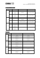
Generally, output processing functions are divided as Fig. A.
Limiter
Crossover
LevelPEQ Delay PEQ Delay
Limiter Level
Crossover
PEQ Delay
From Mixer
Same as above
Left Cluster
Right Cluster
Limiter Level
Limiter Level
Cluster unit
Cross over filtering and Each
driver (HF or LF) setting.
Speaker box unit
PEQ
PEQ
PEQ
PEQ
Delay
Delay
Delay
Delay
Each driver (HF or LF) unit
Fig. A: General output processing functions
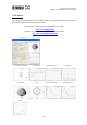
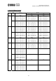
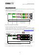
See Fig. B. Cluster EQ and Cluster Delay can be integrated to digital mixer.
Crossover, Polarity, Delay, PEQ, level and Limiter for each driver are integrated to Speaker
processor component (this example, “Speaker Processor 2Way” in DME). And each parameter
(Crossover frequency, etc.) is provided on the Yamaha website (http://www.yamahaproaudio.com/
).
Fig. B: Rearrangement of Output processing function
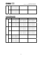
So, by using DME and digital mixer, the processing configuration will be simplified as Fig. C.
Limiter
Crossover
LevelPEQ Delay PEQ Delay
Limiter Level
Crossover
PEQ Delay
Same as above
Left Cluster
Right Cluster
Limiter Level
Limiter Level
PEQ
PEQ
PEQ
PEQ
Delay
Delay
Delay
Delay
Each model’s default
parameters are provided
by Yamaha
Operator may change these parameters
.
Yamaha digital mixers have EQ and delay
on every output channel
These parameters depend on
the installation environment and
are rarely changed after initial
set up.
Digital mixer