
User Manual


ENGLISH
Part Names and Functions
MY16-MD64 Owner’s Manual
5
C
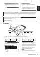
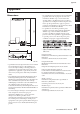
[COAXIAL IN][COAXIAL OUT] Connectors
These are BNC connectors that can be connected via a 75
ohm coaxial cable to other MADI devices for transmission
and reception of the audio and control signals.
NOTE:
Cables up to 100 meters in length can be used.
D
ACTIVE INPUT Indicators
The indicator at the [OPTICAL IN] or [COAXIAL IN]
connector that receives the available signals blinks green.
NOTE:
The indicator does not blink if the settings for the MADI
channel mode and sampling frequency of the received
signals and those for SW1/SW2 differ. Set these
switches before you use the card.
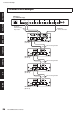
■
Switches
Set these switches as appropriate for your situation and for the device in which the card is installed.
A
MADI Channel Mode (SW1)
NOTE:
The 56-channel mode conforms to AES10-1991. The
64-channel mode conforms to AES10-2003.
B
Sampling Frequency (SW2)
NOTE:
This card supports only Double Speed mode when
running at 88.2/96kHz. (Double Channel mode is not
supported.)
C
Card ID (SW3)
Typically set this switch to the [Emu.] position. If you set
this switch to the [Emu.] position and switch
2
(SW2) to
the [48K] position, the host device will recognize the card
as a Yamaha MY16-AT digital I/O card. If you set this
switch to the [Emu.] position and switch
2
(SW2) to the
[96K] position, the host device will recognize the card as a
Yamaha MY8-AE96 digital I/O card. If you use the card in
a coming host device that supports the Native mode,
setting this switch to the [Nat.] position enables you to
make best use of the MY16-MD64 function.
D
SW101
Leave this switch permanently set to the [OFF] position
during use. Please do not change this setting. Otherwise
the card will not operate properly.
Redundant OPTICAL/COAXIAL inputs
If the card receives a signal available for both the [OPTICAL IN] connector and the [COAXIAL IN] connector, the OPTICAL signal
will take priority. Also, if the OPTICAL signal encounters technical difficulty (such as a disconnection of the fiber optic cable), the
input signal automatically switches to the COAXIAL signal, enabling the card to take advantage of its redundant inputs. However,
the sound is cut off when automatically switched.
Serial communication between Yamaha devices
You can control the internal head amplifiers of a Yamaha digital mixing engine DME24N from a Yamaha digital mixing console LS9
by installing the card in each device.
Firmware version 3.04 or higher is required for the DME24N. You can download the most recent firmware from the following
Yamaha web site.
http://www.yamahaproaudio.com/
SW3SW1
56ch 64ch Emu.
SW2
48K 96K Nat.
123
4
SW101
OFF
Mode Position Position
56 channel
56ch
64 channel
64ch
Mode Position Position
44.1/48 kHz 48K
88.2/96 kHz 96K
Mode Position Position
Emulation Emu.
Native Nat.