
User Manual


8 MY8-SDI-ED Owner’s Manual
Regardless of the [IN 1–4] settings, for those groups that were not selected via the
[OUT 1–4] switch settings, audio signals of those groups that are routed to the
INPUT connector will be embedded as is and output. For example, if neither
Group 2 nor Group 4 were selected via the [OUT 1–4] switch settings, audio
signals of those groups routed to the INPUT connector will be embedded as is
and output.
Note:
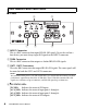
• If only one switch is set to ON, audio will be input/output to/from ports 1–4 , but not to/
from 5–8.
• If all four switches are set to OFF, no audio will be input or output to any ports 1–4 and
5–8.
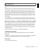
• If you attempt to set more than two GROUP SELECT switches to ON, only the first two
switches (in ascending order) will turn on for both IN and OUT.
For example, if you attempt to set the IN 2, IN 3 and IN 4 switches to ON, Group 2 and
Group 3 audio will be routed to input ports 1–4 and 5–8 of the slot respectively, but audio
will not be input from Group 4.
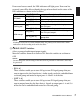
Switch setting IN/OUT 1 IN/OUT 2 IN/OUT 3 IN/OUT 4
Selected group
(Channels)
Group1
(ch1-4)
Group2
(ch5-8)
Group3
(ch9-12)
Group4
(ch13-16)
1–4
5–8
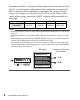
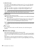
SDI signal
Input ports of the slot
(host device)
Group2: ch5-8
Group3: ch9-12
Group1: ch1-4
Group4: ch13-16