ProVisionaire Design Component Guide
Contents Contents 1. Introduction . . . . . . . . . . . . . . . . . . . . . . . . . . . . . . . . . . . . . . . . . . . . . . . . . . . . . . . . . . . . . . . . . . . . . . . . . 3 2. Audio Components . . . . . . . . . . . . . . . . . . . . . . . . . . . . . . . . . . . . . . . . . . . . . . . . . . . . . . . . . . . . . . . . . . . . 4 2.1. The Difference Between Mono, Stereo, and Multi . . . . . . . . . . . . . . . . . . . . . . . . . . . . . . . . . . . . . . 4 2.2. How to Control Control Signals . . .
Contents 3.4. Input (Normalized Value): Radio Button . . . . . . . . . . . . . . . . . . . . . . . . . . . . . . . . . . . . . . . . . . . . 3.5. Input (Value): Radio Button . . . . . . . . . . . . . . . . . . . . . . . . . . . . . . . . . . . . . . . . . . . . . . . . . . . . . . 3.6. Input (Normalized Value): Fader . . . . . . . . . . . . . . . . . . . . . . . . . . . . . . . . . . . . . . . . . . . . . . . . . . 3.7. Input (Value): Fader . . . . . . . . . . . . . . . . . . . . . . . . . . . . . . . . .
1. Introduction 1. Introduction This document explains how to use the audio components and control components that are supported by the DME7. For other devices such as processors and amplifiers, several of the components used by the DME7 are common with these devices, so you will be able to understand how to use them by reading this document. Information * The illustrations and screens as shown in this guide are for instructional purposes only. * Dante® is registered trademarks of Audinate Pty Ltd.
2. Audio Components 2. Audio Components 2.1. The Difference Between Mono, Stereo, and Multi Here we explain the screen for the components/editors handled by the DME7. When a component is placed on the design sheet, the following screen will initially be displayed. (Example: Fader) These components can control multiple channels (Ch) either individually or collectively by specifying Mono, Stereo, or Multi.
2. Audio Components 2.2. How to Control Control Signals The DME7 uses an area called the Control Layer to connect control component and audio component parameters, and which makes the creation of complex control signal configurations possible. Refer to the ProVisionaire Design User Guide for the procedures. Refer to the description in this manual for each audio component for information about the behavior when the audio parameters are controlled in the Control layer. 2.2.1.
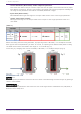
2. Audio Components • Control Parameter (Red outline): Audio component parameter This shows the name of the port used to input the control signal from an external source (Input Port Name), the name of the port that outputs the change notification (Output Port Name), and the range of the parameter that will be controlled (Parameter range). • Input Value (Blue outline): Recommended data type and range for the input value used to control the target parameter.
2. Audio Components 2.3. Acoustic Echo Canceller (AEC) Acoustic Echo Canceller (AEC) is a function that eliminates the acoustic echo that can be a problem during remote conferencing when sound from a speaker is picked up by microphones, or steady-state noise such as produced by air conditioning systems. By providing the other party with clear audio from which such echo and noise have been removed, conversation during the remote conference can be conducted smoothly.
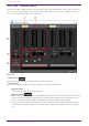
2. Audio Components 2.3.1. “AEC” component editor This specifies AEC-related settings. The left side of the screen is Reference, and the right side of the screen is for settings related to microphones connected to Mic In 1–16. If there are more than five mics, a scroll bar will be displayed at the bottom. Mic. 1–16 ① [ON] button Switches between enabling or disabling AEC for each microphone. ② Level meters These show the input/output levels and information related to acoustic echo.
2. Audio Components ・Speaker volume is loud. ・Mic gain (MIC1, MIC2) is high. ・The mic and speaker are positioned close together. • [ERLE] level meter Shows in real time the amount of echo (dB) removed by the AEC. The more negative the ERLE value becomes, the more echo is removed by the AEC. • [OUT] level meter Shows the output level from the AEC. ③ [GAIN] knob This sets the mic gain. ④ [AEC EFFECT] type This sets the AEC effect. There are 4 options: Soft/Medium/Hard/Custom.
2. Audio Components 2.3.2. Advanced Settings window Mic. 1–16 [LINEAR AEC] knob/[ECHO SUPP] knob These two are echo canceling functions that use different methods. As the numeric value is increased, more echo cancellation is performed, but if it is raised too high, each one will cause a different type of negative effect. Therefore, it is necessary to understand their negative effects and maintain a balance of the two to keep the settings within a necessary and sufficient range.
2. Audio Components Reverberation is not removed when set to 0. Best used with "DEREVERB" set to Off (0) for rooms with almost no reverberation. This can only be set when Custom has been selected for [AEC EFFECT]. ⑤ [REVERB TIME] knob Sets the reverberation time inside a room. Normally, no change from the Default value of 0.6 s is necessary. When using the AEC in a glass room or other location that has more reverberation than a normal conference room, adjust to increase the target REVERB TIME to 0.6–1.0 s.
2. Audio Components 2.3.3. Control Parameter types of the input/output values for each Port Input Value Type Value Range Control Parameter Output Value Input Port Name Paramete Output r Range Port Name Type −∞–10.00 ● Ref Gain Value dB −∞–10.00 ● Ref Gain 0.00–1.00 Value Num 0,1 Value dB Value Range dB −∞–10.00 Num 0,1 −∞–10.00 ● Mic −∞–10.00 ● Mic Value Gain Mic1 Gain Mic1 0.00–1.00 dB −∞–10.
2. Audio Components 2.4. Ambient Noise Compensator (ANC) ANC (Ambient Noise Compensator) is a function that boosts or attenuates the level of the program source according to the level that is being input via an ambient noise detection mic. The ANC function provided by the DME7 is a gap-type ANC that detects silent intervals such as between songs, detects the noise level during those intervals, and varies the level accordingly.
2. Audio Components ① ANC [ON] button Switches the ANC function between enabled and disabled. ② AMIBIENT • Level meter Shows the level of ambient noise. • [THRESHOLD] knob Specifies the average level of ambient noise. If the level of ambient noise exceeds this value, the level of the program source is raised; if the level is lower than this value, the level of the program source is lowered. ③ GAP • [THRESHOLD] knob Specifies the threshold value of the program source.
2. Audio Components • [RESPONSE TIME] knob Specifies the response speed for level compensation. • Level meter Indicates the output level of the program source after compensation. 2.4.2.
2. Audio Components 2.5. Audio Detector Audio Detector is a function that detects audio signals. By registering the detection indicator to the GPI Output, a signal can be output from the unit’s GPI [OUT] connector when an audio signal is detected. 2.5.1. ”Audio Detector” component editor Here you can specify the threshold value of the audio signal, and see whether an input exceeding the threshold value has been detected.
2. Audio Components 2.5.2.
2. Audio Components 2.6. Auto Gain Control (AGC) AGC (Auto Gain Controller) is a function that automatically compensates the gain according to the input level, keeping a constant output level for an incoming signal whose level is changing. For example, differences in how closely and how loudly a person is speaking into a mic can make their amplified voice vary in volume, making it less intelligible. In such cases, the volume will be automatically adjusted within a fixed range.
2. Audio Components If the input is above the Threshold value and below –18 dB, the output is set to –18 dB. If the input is above the Threshold value and above –18 dB, the output level is adjusted by the Ratio value. If the noise gate is on, the volume is adjusted so that input and output are the same level at –60 dB, and then adjusted so that the output is –18 dB when it reaches the Threshold value. If the input is above the Threshold value and below –18 dB, the output is set to –18 dB.
2. Audio Components 2.6.2. Control There are no parameters that can be controlled through the Control layer.
2. Audio Components 2.7. Combiner: Room Combiner, Room Combiner plus Automixer This function is used when audio signals are shared between multiple rooms, or when a single room is partitioned in varying ways. The audio signal outputs are changed according to how the rooms are divided or connected. The DME7 provides two types of combiner: “Room Combiner” and “Room Combiner plus Automixer.” The latter adds Dan Dugan Automixer functionality.
2. Audio Components If you want to reassign the room numbers, click the room numbers consecutively. During editing, if you want to renumber the rooms starting from 1, click the [Restart numbering] button. After you have finished renumbering, click the [Next] button. The screen changes to a screen where you can specify the number of mics placed in the rooms.
2. Audio Components In the dropdown list, select the number of mics used by all rooms, and click or drag the cells of the mics to be assigned to the rooms. After you have finished making assignments, click the [Create] button. “Room Combiner plus Automixer” is placed in the design sheet. “Room Combiner” does not have this screen.
2. Audio Components The inputs are assigned as follows, starting from the top.
2. Audio Components 2.7.1. “Room Combiner” component editor/”Room Combiner plus Automixer” component editor Here you can specify which rooms are combined. ① Rooms This area shows the rooms. When you click a button located between two rooms (the combine button), the rooms are combined. Combined rooms are shown in the same color. When you double-click or rightclick a tile and choose [Open Parameter Window], the combiner parameter setting window appears.
2. Audio Components 2.7.2. Combiner parameter setting window (Room Combiner) Here you can view and edit the parameters of all rooms. When rooms are connected, [ROOM IN] can be adjusted for each room; however, the setting of the lowest-numbered room takes priority for [PAGING]/[BGM]/[ROOM OUT]. ① Index Shows the number and color assigned to the room. Connected rooms are shown in the same color. ② [NAME] boxx Indicates the room name. You can double-click the name and edit it.
2. Audio Components 2.7.3. Combiner parameter setting window (Room Combiner plus Automixer) This mixes [LOCAL IN], [BGM], and [PAGING] with each room’s mic inputs that have been auto-mixed and output by the Dugan Automixer. Here you can view and edit the parameters of all rooms. When rooms are connected, [LOCAL IN] can be adjusted for each room; however, the setting of the lowest-numbered room takes priority for parameters other than [LOCAL IN]. ① Index Shows the number and color assigned to the room.
2. Audio Components 2.7.4. Control (Room Combiner) Parameter types of the input/output values for each Port Input Value Type Control Parameter Output Value Range Input Port Name Paramete Output r Range Port Name Type ● Combine 1+2 OFF:0, ON:1 Value Num 0,1 Value dB Num OFF:0, ON:1 −∞–10.00 ● RoomIn −∞–10.00 ● RoomIn Value Level Level 0.00–1.00 Room1 Room1 dB −∞–10.00 Value Num 0,1 Num OFF:0, ON:1 Value dB −∞–10.00 ● Paging −∞–10.00 ● Paging Value Level Level 0.00–1.
2. Audio Components 2.7.5. Control (Room Combiner plus Automixer) Parameter types of the input/output values for each Port Input Value Type Control Parameter Output Value Range Input Port Name Paramete Output r Range Port Name Type ● Combine 1+2 OFF:0, ON:1 Value Num 0,1 Value dB Num OFF:0, ON:1 −∞–10.00 ● −∞–10.00 ● Value Mics.Leve Mics.Leve 0.00–1.00 l Room1 l Room1 dB −∞–10.00 Value Num 0,1 Num OFF:0, ON:1 Value dB −∞–10.00 ● LocalIn −∞–10.00 ● LocalIn Value Level Level 0.00–1.
2. Audio Components Value Num 0,1 ● override Ch01 OFF:0, ON:1 ● override Ch01 Value Num OFF:0, ON:1 Value Num 0,1,2 ● mode Ch01 0:auto, 1:man, 2:mute ● mode Ch01 Value Num 0:auto, 1:man, 2:mute Value Num 0,1 ● Room override Room1 OFF:0, ON:1 ● Room override Room1 Value Num OFF:0, ON:1 Value Num 0,1 ● Room mute Room1 OFF:0, ON:1 ● Room mute Room1 Value Num OFF:0, ON:1 2.7.6.
2. Audio Components 2.8. DCA DCA is a function that registers the input system channels into 8 groups, and allows for operations such as simultaneous muting, or batch level operation using the Offset knob. If the input system channels all belong to the same group, the levels can be operated with a single Offset knob while still retaining the level differences between the channels. This is useful when grouping mics for drums. 2.8.1.
2. Audio Components : On :Off (mute) If any input signal has been registered to multiple groups, that signal will be muted when any of the groups to which it has been registered are turned off. ④ [Offset] knob The offset value added to the input channels registered to the group. If any input signal has been registered to multiple groups, the offset values from any of the groups to which it has been registered will be added before it is output.
2. Audio Components 2.9. Delay In a sound system that includes multiple speaker units, it may appear to a listener that the voice of the person talking is originating from a nearby speaker unit, rather than from the actual person. In such cases, you can correct the perceived localization by delaying the audio of the nearby speaker unit in proportion to the distance between the speaker unit near the person who is talking and the speaker unit that is far from that person.
2. Audio Components 2.9.2. Control Parameter types of the input/output values for each Port Input Value Type Control Parameter Output Value Range Input Port Name Paramete Output r Range Port Name Type ● On OFF:0, ON:1 Value Num 0,1 Value dB −∞–10.00 ● Delay Time 0.00–1.00 Normalized 34 | ProVisionaire Design Component Guide ● On −∞–10.00 ● Delay Time Range Value Num OFF:0, ON:1 Value dB −∞–10.
2. Audio Components 2.10. Dynamics: Compressor This type of signal processing compresses the dynamic range. Use this to prevent problems that can occur in the sound if the input exceeds a certain level (threshold). When placing this in the design sheet, select either Mono, Stereo or Multi. The illustrations used in the following explanation are for the case of Stereo. The bottom input is for inputting the key-in signal. 2.10.1.
2. Audio Components ① Compressor [ON] button Switches the compressor function between enabled and disabled. ② Compressor curve This shows the effect as a graph. The horizontal axis is the input signal level, and the vertical axis is the output signal level. ③ [GR] meter Indicates the amount of gain reduction. ④ [KEY IN] list box From this list, select the input signal that is used as the key-in signal; that is, the reference signal that causes the compressor to operate. The following choices are provided.
2. Audio Components ⑩ [GAIN] knob Sets the gain of the output signal. ⑪ [OUTPUT]メーター Shows the output signal level. 2.10.2. Control There are no parameters that can be controlled through the Control layer.
2. Audio Components 2.11. Dynamics: Comp260 This is an analog-flavored compressor built using Yamaha’s proprietary VCM (Virtual Circuitry Modeling) technology. It emulates the characteristics of compressors and limiters of the mid-1970s, which are now a standard for live sound reinforcement. This compressor has faithfully modeled the VCA (Voltage Controlled Amplifier) circuit and the RMS (Root Mean Square) detection circuit. Compression curve (Knee) can be set to Hard, Medium, or Soft.
2. Audio Components ① Comp260 [ON] button Switches between enabling or disabling the Comp260 function. ② Compressor curve This shows the effect as a graph. The horizontal axis is the input signal level, and the vertical axis is the output signal level. ③ [GR] meter Indicates the amount of gain reduction. ④ [KEY IN] list box From this list, select the input signal that is used as the key-in signal; that is, the reference signal that causes the compressor to operate. The following choices are provided.
2. Audio Components ⑦ [KNEE] knob Specifies how Comp260 will be applied. With the [HARD] setting, it will operate like a limiter. If the [HARD] setting produces an unnatural impression, raise the value. However, raising the value excessively will increase the amount of compression for the portion below the threshold level. ⑧ [ATTACK] knob Specifies the attack time (the time from when the input signal exceeds the threshold until the maximum Comp260 effect is reached).
2. Audio Components 2.12. Dynamics: De-Esser Detects only high-frequency consonant components such as sibilant sounds (hissing or buzzing sounds) in vocals and compresses that band. When placing this in the design sheet, select either Mono or Stereo. The illustrations used in the following explanation are for the case of Stereo. 2.12.1. ”De-Esser” component editor ① De-Esser [ON] button Switches the De-Esser function between enabled and disabled. ② Dynamics graph This shows the effect as a graph.
2. Audio Components ⑥ [Q] knob Specifies the Q of the filter. When the type is H.SHELF, the Q is not displayd. ⑦ [Freq.] knob Specifies the cutoff frequency of the filter. ⑧ [OUTPUT] meter Shows the output signal level. 2.12.2.
2. Audio Components 2.13. Dynamics: Ducker This function reduces the audio signal level (volume) of the input channel when an audio signal is input to a specific channel. For example if this is used on background music and the key-in source is assigned to a channel with a mic connected, the background music will automatically diminish when an announcement is made into that mic, and automatically return to the original volume when the announcement is over.
2. Audio Components ① Ducker [ON] button Switches the Ducker function between enabled and disabled. ② Ducking curve This shows the effect as a graph. The horizontal axis is the input signal level, and the vertical axis is the output signal level. ③ [GR] meter Indicates the amount of gain reduction. ④ [KEY IN] list box From this list, select the input signal that is used as the key-in signal; that is, the reference signal that causes Ducker to operate. The following choices are provided.
2. Audio Components ⑧ [HOLD] knob Specifies the hold time (the time from when the input signal falls below the THRESHOLD until attenuation begins to be removed). ⑨ [RELEASE] knob Specifies the release time (the time from when the hold time specified by the [HOLD] knob has elapsed until Ducker is no longer applied). The setting is expressed as the time required for the level to change 6 dB. ⑩ [OUT] meter Shows the output signal level. 2.13.2.
2. Audio Components 2.14. Dynamics: Gate This type of signal processing passes the audio signal only while it exceeds a specified volume. Use this to cut low-level noise, such as when there is no input from a mic, or when the input is below a specified level (the threshold value). When placing this in the design sheet, select either Mono, Stereo or Multi. The illustrations used in the following explanation are for the case of Stereo. The bottom input is for inputting the key-in signal. 2.14.1.
2. Audio Components ④ [KEY IN] list box From this list, select the input signal that is used as the key-in signal; that is, the reference signal that causes the gate to operate. The following choices are provided. • [Self] For a monaural channel component, the input signal is used as the trigger source. • [L] For a stereo channel component, the L input signal is used as the trigger source. • [R] For a stereo channel component, the R input signal is used as the trigger source.
2. Audio Components 2.14.2.
2. Audio Components 2.15. Dynamics: Limiter Input signals that exceed the threshold value are compressed ∞:1, preventing signals greater than the threshold value from being output. This is used mainly to keep power amps and speaker systems from being damaged by excessive input. When placing this in the design sheet, select either Mono, Stereo or Multi. The illustrations used in the following explanation are for the case of Stereo. The bottom input is for inputting the key-in signal. 2.15.1.
2. Audio Components ① Limiter [ON] button Switches the limiter function between enabled and disabled. ② Limiter curve This shows the effect as a graph. The horizontal axis is the input signal level, and the vertical axis is the output signal level. ③ [GR] meter Indicates the amount of gain reduction. ④ [KEY IN] list box From this list, select the input signal that is used as the key-in signal; that is, the reference signal that causes the limiter to operate. The following choices are provided.
2. Audio Components ⑦ [RELEASE] knob Specifies the release time (the time from when the input signal falls below the threshold until the limiter effect is no longer applied). ⑧ [OUTPUT] meter Shows the output signal level. 2.15.2. Control Parameter types of the input/output values for each Port Input Value Type Control Parameter Output Value Range Input Port Name Paramete Output r Range Port Name Type ● On OFF:0, ON:1 Value Num 0,1 Value dB - Normalized - Num OFF:0, ON:1 −∞–10.
2. Audio Components 2.16. Dynamics: Paging Ducker This function controls the audio signal level of the program source by the on/off status of the TRIGGER [ON] button. Since the TRIGGER [ON] button and [RANGE] indicator can be registered to GPI or the Remote Control Setup List, they can be controlled from an external device or made to light an external LED. When placing this in the design sheet, select either Mono, Stereo or Multi.
2. Audio Components ① Paging Ducker [ON] button Switches the paging ducker function between enabled and disabled. ② TRIGGER [ON] button If you turn this on, the audio signal level of the program source is lowered to the value specified by the [RANGE] knob. If you turn this off, the audio signal level of the program source returns to its original level. Set this so that it operates in tandem with the talk switch/button of the paging mic.
2. Audio Components 2.17. Dynamics: Program Ducker When the level of the key-in signal exceeds the threshold, the output signal is attenuated (or the attenuated signal is returned to its original level). When placing this in the design sheet, select either Mono, Stereo or Multi. The illustrations used in the following explanation are for the case of Stereo. The bottom input is for inputting the key-in signal. 2.17.1. ”Program Ducker” component editor ① [KEY IN] meter Shows the key-in signal level.
2. Audio Components When the key-in signal is not detected, the output level is attenuated, and when the key-in signal is detected, the output level is returned to the original level. The normal attenuation level is set using RANGE. The operating output level is 0 dB. ⑤ [ATTACK] knob Configures the time it takes to reach the target output level after detecting the key-in signal. ⑥ [RANGE] knob Sets the level of attenuation.
2. Audio Components 2.17.2. Control There are no parameters that can be controlled through the Control layer.
2. Audio Components 2.18. Effect: Ping Pong Delay This is a delay effect that repeats the delay sound alternately left and right at equal intervals. 2.18.1. ”Ping Pong Delay” component editor ① Pink Pong Delay [ON] button Switches the Ping Pong Delay function between enabled and disabled. ② [DELAY] knob Specifies the delay time. This will change in conjunction when the BPM or NOTE is changed. ③ [BPM] knob Specifies the tempo.
2. Audio Components ⑥ [DRY/WET] knob This control enables you to adjust the mix balance of the dry and wet (effect) sounds. When the balance is 0%, only the dry sound is output. When the balance is 100%, only the wet sound is output. ⑦ [HIGH RATIO] knob Sets the amount of the wide-area component of the feedback. ⑧ [HPF] knob Sets the high pass filter’s cutoff frequency. ⑨ [LPF] knob Sets the low pass filter’s cutoff frequency. 2.18.2.
2. Audio Components 2.19. Effect: REV-X REV-X is a reverb algorithm that provides a high-density, richly reverberant sound quality, with smooth attenuation, and spread and depth that work together to enhance the original sound. You can choose one of three programs to suit the acoustic sound field and your intentions: REV-X Hall, REV-X Room, and REV-X Plate. Input and output are stereo, with 1L at the top and 1R below. 2.19.1.
2. Audio Components ④ Initial Delay Duration of time between sound input and the start of reverberation. Higher values delay the start of reverberation. ⑤ Decay Shape of reverberation envelope. Reverberation characteristics are determined by the value. ⑥ Room Size Size of space. Higher values simulate larger spaces. This value is linked with the Reverb Time value. When you change this value, the Reverb Time value changes. ⑦ Diffusion Density and spread of reverberation.
2. Audio Components ⑲ [DRY/WET] knob This control enables you to adjust the mix balance of the dry and wet (effect) sounds. When the balance is 0%, only the dry sound is output. When the balance is 100%, only the wet sound is output. 2.19.2.
2. Audio Components 2.20. EQ: GEQ Here you can make GEQ settings. When placing the GEQ in the design sheet, you can select the number of bands from 7, 15, or 31. The illustrations shown here are for when 31 bands are selected. When placing this in the design sheet, select either Mono, Stereo or Multi and select the number of bands. The illustrations used in the following explanation are for the case of Stereo. 2.20.1. ”GEQ” component editor When Multi is selected, the meter is not displayed.
2. Audio Components ④ GEQ [ON] button Switches the GEQ function between enabled and disabled. ⑤ Bypass buttons Specify whether each band is bypassed. If you click a button to make it light, that band is bypassed. ⑥ Gain faders Adjust the output gain of each band. ⑦ [±15]/[±12]/[±6]/[‒24] buttons Select the range of GEQ gain adjustment. When you click a button, the display of the gain faders and EQ curve will change to the range you select. ⑧ [FLAT] button Moves all gain faders to the 0 position.
2. Audio Components 2.21. EQ: PEQ Here you can make PEQ settings. When placing the PEQ in the design sheet, you can select the number of bands. The illustrations shown here are for when 8 bands are selected. When placing this in the design sheet, select either Mono, Stereo or Multi and select the number of bands. The illustrations used in the following explanation are for the case of Stereo. 2.21.1. “PEQ” component editor ① EQ curve This shows the response as a graph.
2. Audio Components • L.SHELF (Low Shelf) The volume of the entire low-frequency region below the specified frequency will be boosted or cut. Use this for purposes such as bass boost. [6dB/Oct] and [12dB/Oct] specify the amount of attenuation per octave. • H.SHELF (High Shelf) The volume of the entire high-frequency region above the specified frequency will be boosted or cut. Use this for purposes such as high boost. [6dB/Oct] and [12dB/Oct] specify the amount of attenuation per octave.
2. Audio Components 2.22. Fader This adjusts the output level of each channel. When placing this in the design sheet, select either Mono, Stereo or Multi, and specify the number of channels. The illustration used in the following explanation is for the case of eight monaural channels. When Stereo is selected, the inputs and outputs are 1L, 1R, 2L, and 2R from the top. 2.22.1. “Fader” component editor MWhen Multi is selected, the meter is not displayed. Please use the separate Meter component.
2. Audio Components 2.22.2. Control Parameter types of the input/output values for each Port Input Value Type Value Range Output Value Input Port Name Paramete Output r Range Port Name Type −∞–10.00 ● Level Ch1 Value dB −∞–10.00 ● Level Ch1 0.00–1.00 Num 0,1 Normalized Value Control Parameter ● On Ch1 OFF:0, ON:1 ● On Ch1 Value Range dB −∞–10.
2. Audio Components 2.23. Feedback Suppressor: Notch FBS The Feedback Suppressor (subsequently referred to as FBS) is a function that prevents the unpleasant acoustic feedback that occurs when sound from a speaker is picked up by a mic and re-amplified. In addition to being unpleasant, acoustic feedback places a strain on the speakers, and can damage them. To prevent such feedback, place the speakers so that their sound will not be picked up by the mic and amplified.
2. Audio Components ⑥ [CLEAR] button Clears the filter settings. ⑦ [Freq.] Displays the frequencies of the filters that were applied. Up to seven filters will be applied. • The indicator will light when the following occurs. ◦ When a frequency is displayed ◦ When a currently-displayed frequency is rewritten • When using FIXED, calculation will continue repeatedly even after all seven filters have been displayed, for example to combine the frequencies that are closest to each other.
2. Audio Components 2.23.2.
2. Audio Components 2.24. Feedback Suppressor: Pitch Shift FBS The Feedback Suppressor (subsequently referred to as FBS) is a function that prevents the unpleasant acoustic feedback that occurs when sound from a speaker is picked up by a mic and re-amplified. In addition to being unpleasant, acoustic feedback places a strain on the speakers, and can damage them. To prevent such feedback, place the speakers so that their sound will not be picked up by the mic and amplified.
2. Audio Components 2.24.2.
2. Audio Components 2.25. Filter: BPF A filter allows a specific frequency region to pass and attenuates other frequency regions. The DME7 provides three types of filter: BPF (band-pass filter), HPF (high-pass filter), and LPF (lowpass filter). Select either Mono, Stereo or Multi when you place this component in the design sheet. The illustrations used in the following explanation are for the case of Stereo.
2. Audio Components 2.25.1. “BPF” component editor This filter passes the signal in a specified frequency band, and attenuates the signal in other frequency regions. ① BPF [ON] button Enables or disables the BPF. ② [HPF]/[LPF] list box Select the amount of attenuation per octave, and the type of filter. ③ [Freq.] knobs Specify the cutoff frequency of the HPF and LPF. ④ [Gc] knob When [AdjustGc] (Adjustable Gc) is selected in the [HPF]/[LPF] list box, these knobs specify the gain at the cutoff frequency.
2. Audio Components 2.26. Filter: HPF A filter allows a specific frequency region to pass and attenuates other frequency regions. The DME7 provides three types of filter: BPF (band-pass filter), HPF (high-pass filter), and LPF (lowpass filter). Select either Mono, Stereo or Multi when you place this component in the design sheet. The illustrations used in the following explanation are for the case of Stereo.
2. Audio Components 2.26.1. “HPF” component editor This filter passes the signal of the region above the specified frequency, and attenuates the signal in the lower frequency region. ① HPF [ON] button Enables or disables the HPF. ② [HPF] list box Selects the amount of attenuation per octave, and the type of filter. ③ [Freq.] knob Specifies the cutoff frequency. ④ [Gc] knob When [AdjustGc] (Adjustable Gc) is selected in the [HPF] list box, this knob specifies the gain at the cutoff frequency. 2.26.2.
2. Audio Components 2.27. Filter: LPF A filter allows a specific frequency region to pass and attenuates other frequency regions. The DME7 provides three types of filter: BPF (band-pass filter), HPF (high-pass filter), and LPF (lowpass filter). Select either Mono, Stereo or Multi when you place this component in the design sheet. The illustrations used in the following explanation are for the case of Stereo.
2. Audio Components 2.27.1. “LPF” component editor This filter passes the signal of the region below the specified frequency, and attenuates the signal in the upper frequency region. ① LPF [ON] button Enables or disables the LPF. ② [LPF] list box Selects the amount of attenuation per octave, and the type of filter. ③ [Freq.] knob Specifies the cutoff frequency. ④ [Gc] knob When [AdjustGc] (Adjustable Gc) is selected in the [LPF] list box, this knob specifies the gain at the cutoff frequency. 2.27.2.
2. Audio Components 2.28. Input/Output: Dante In This is the input jack of the DME7. The number of Dante Input channels is determined by the number of activated device licenses. 2.28.1. “Dante In” component editor This shows the level of the audio signals that are being input from the Dante ports. 2.28.2. Control There are no parameters that can be controlled through the Control layer.
2. Audio Components 2.29. Input/Output: USB In This is the input jack of the DME7. 2.29.1. “USB In” component editor This shows the level of the audio signals that are being input from the USB ports. 2.29.2. Control There are no parameters that can be controlled through the Control layer.
2. Audio Components 2.30. Input/Output: Dante Out This is the output jack of the DME7. The number of Dante Output channels is determined by the number of activated device licenses. 2.30.1. “Dante Out” component editor Here you can make settings related to Dante output. ① Channel index Indicates the Dante channel number. ② Level meter Indicates the analog output level. ③ [GAIN] knob Adjusts the output gain. ④ [INV] button Switches the polarity of the output signal.
2. Audio Components 2.30.2. Control Parameter types of the input/output values for each Port Input Value Type Value Normalized Range dB Control Parameter Output Value Input Port Name Paramete Output r Range Port Name Type −∞–10.00 ● Gain Out01 Value −∞–10.00 ● Gain Out01 0.00–1.00 82 | ProVisionaire Design Component Guide Range dB −∞–10.
2. Audio Components 2.31. Input/Output: USB Out This is the output jack of the DME7. 2.31.1. “USB Out” component editor Here you can make settings related to USB output. ① Channel index Indicates the USB channel number. ② Level meter Indicates the analog output level. ③ [GAIN] knob Adjusts the output gain. ④ [INV] button Switches the polarity of the output signal. ⑤ Port name Shows or edits the port name. This is linked with the “Label” of the component’s ports.
2. Audio Components 2.31.2. Control Parameter types of the input/output values for each Port Input Value Type Value Normalized Range dB Control Parameter Output Value Input Port Name Paramete Output r Range Port Name Type −∞–10.00 ● Gain Out01 Value −∞–10.00 ● Gain Out01 0.00–1.00 84 | ProVisionaire Design Component Guide Range dB −∞–10.
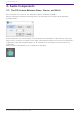
2. Audio Components 2.32. Input/Output: SD Card By using commercially available SD memory cards, the DME7 can play music, sound effects, and other audio files. The DME7 can play MP3 and WAV audio file formats. To play audio files stored on an SD memory card, the SD Card component editor must be set. If you want to output audio from an SD card, place an SD Card component. 2.32.1. ”SD Card” component editor Selects, plays, and adjusts the volume of audio files.
2. Audio Components 2.32.2. “SD Card File Manager” dialog box This dialog box enables you to register a file you wish to play with the SD Card component. The list in this dialog box is also used to play files via the DCP or GPI. This screen can also be opened by clicking on the [Tools] button on the DME7 design sheet then clicking [SD Card File Manager]. [Edit] button Click this button to open the “SD Card File Settings” dialog box. Menu button Click this button to open the following context menu.
2. Audio Components If you selected “Play 1 Song” for “File/Folder” in the “Settings” dialog box, “1 Song” will appear in this column. If you selected “Play all songs in a folder,” “Folder” will appear in this column. • File/Folder Indicates the file name or folder name. • Play Mode Indicates the specified Play Mode. • Go to the top Indicates the setting that was specified in the [Go to the top when playback stops] check box. • Interval Indicates the interval time.
2. Audio Components 2.32.3. “SD Card File Settings” dialog box [Folder/File] Specifies the file to play. • [Play 1 song] / [Play all songs in a folder] option button If you choose [Play 1 song], only the file currently selected in [SD CARD:/] will play. If you select [Play all songs in a folder], all files saved in the folder selected by [SD CARD:/] will play. • [SD CARD:/] This shows the name of the file or folder that will be played. You can change the name, or enter it directly.
2. Audio Components • [Browse] button When you click this, a screen will appear, allowing you to select the file or folder to be played. If you choose [Play 1 song], select a file. If you choose [Play all songs in a folder], select a folder. [Play Mode] • [Normal]/[Repeat]/[Shuffle Repeat] This specifies the play mode for the file or files. If you choose [Normal], the specified file or files in the folder will play once.
2. Audio Components ② [Play] A drop-down list is displayed when clicked, and the files registered in the SD Card File Manager can be selected. ③ [List] button Opens the “SD Card File Manager” dialog. ④ Playback Control 2.32.4.
2. Audio Components 2.33. Meter This displays the signal level of each channel. Specify the number of channels when you place this component in the design sheet. The illustration used in the following explanation is for the case of eight channels. 2.33.1. ”Meter” component editor This displays the output level of each channel. ① Channel index Channel numbers are shown in units of eight channels. ② Meter This displays the signal level of each channel.
2. Audio Components 2.33.2. Control Parameter types of the input/output values for each Port Input Value Type Value Range dB Normalized Value Control Parameter Output Value Input Port Name Type Paramete Output r Range Port Name −∞–10.00 ● Attack −∞–10.00 ● Attack Value Range dB −∞–10.00 0.00–1.00 dB −∞–10.00 ● Release Value dB −∞–10.00 Normalized −∞–10.00 ● Release 0.00–1.00 - - −∞–10.00 ● Meter Ch1 Value dB −∞–10.
2. Audio Components 2.34. Mixer: Delay Matrix, Matrix Mixer The DME7 provides four types of mixers: Delay Matrix, Dugan Automixer, Matrix Mixer, and Summer. When placing this component in the design sheet, select the number of channels. The maximum number of inputs and outputs for the Delay Matrix is 64-in/128-out. The maximum number of inputs for the Dugan Automixer is 64 channels. The maximum number of inputs and outputs for the Matrix Mixer is 256-in/256-out.
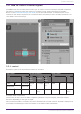
2. Audio Components 2.34.1. “Delay Matrix” component editor / “Matrix Mixer” component editor This mixer places the input channels and output buses in a matrix. In the “Matrix Mixer” component editor you can adjust the group balance for each output bus. In the “Delay Matrix” component editor you can adjust the group balance and delay for each output bus. Here we explain using a screenshot of the “Delay Matrix” component editor.
2. Audio Components ③ Channel matrix Shows the send level and delay for each channel. The vertical axis shows the input channel, and the horizontal axis shows the output channel. A cross-point is displayed when the cursor is placed over this. It changes to selection mode when clicked. Press the up/down arrow keys or hold down the left mouse button and move up or down to change the value. The numeric value can also be entered directly by double clicking. Press the key to move right.
2. Audio Components • [Input Channel(Rows)] ◦ This is the setting for the horizontal axes of the matrix. ◦ On: Turn all of the horizontal axes ON. ◦ Off: Turn all of the horizontal axes OFF. ◦ Nominal/–3 dB/–6 dB/Minimum: Sets the horizontal axis send level to Nominal, –3 dB, –6 dB, or Minimum. ◦ Copy: Copies the horizontal axis settings (both delay time and send level). ◦ Paste: Pastes the copied contents into a different horizontal axis.
2. Audio Components 2.34.2. “One Input to All Outputs” window One input channel and the send levels from the input channel to all output buses are displayed. This window opens when you click the [One Input to All Outputs] window open button of the “Delay Matrix” component editor or the “Matrix Mixer” component editor. Here we explain using a screenshot of the “Delay Matrix - One Input to All Outputs” window. ① Meter Shows the signal level for each output channel.
2. Audio Components ⑥ [INPUT CHANNEL] list box Switches the input channel for which to make settings. ⑦ Input port name Shows or edits the input port name. This is linked with the “Label” of the component’s ports. ⑧ [Tools] Sets the send level from the input channel to [On], [Off], [Nominal], [–3 dB], [–6 dB], or [Minimum]. ⑨ Output port name Shows or edits the output port name. This is linked with the “Label” of the component’s ports. 2.34.3.
2. Audio Components ③ Delay Time knob (“Delay Matrix” only) Specifies the delay time from each input channel to the output bus. You can select the units in the Type list box. ④ Type list box (“Delay Matrix” only) The delay time specified by the Delay Time knob is converted into the units you select. • ms………. Milliseconds • sample…… Number of samples (The range will depend on the sampling frequency setting.) • meter……. Meters/second • feet……..
2. Audio Components 2.35. Mixer: Dugan Automixer In a system used for unscripted speech, the automixer detects the mics that are in use and automatically optimizes the gain distribution, maintaining a consistent system gain between multiple mics without requiring an engineer to be constantly adjusting the faders. The Dugan Automixer provided on the DME7 can automatically adjust the automix gain for up to 64 mics used for speech. In this explanation, we describe using the Dugan Automixer with three mics.
2. Audio Components 2.35.1. “Dugan Automixer” component editor Main control field ① Channel display For input channels 1–8, 9–16, 17–24, 25–32, 33–40, 41–48, 49–56, and 57–64, this area shows each channel’s automix gain (Automix gain) meter and the man (yellow) / auto (green) / mute (red) status. When you select the region of channels 1–8, 9–16, … or 57–64, the channels displayed in the channel control field switch between 1–8, 9–16, … and 57–64.
2. Audio Components ① [level] indicator This lights green when the audio reaches the appropriate level for automixing. ・If the [level] indicator goes dark, raise the input gain. ・If the [level] indicator turns red, lower the input gain. ② Meter The meter provides three display modes: gain (green: automix gain) /input (yellow: input level) /output (blue: output level). The display mode switches each time you press the [meters] button in the main control field.
2. Audio Components • If you turn on the [OVERRIDE] button of the main control field when the [override] button of the channel control field is off, the channel mode changes to “mute.” • When the [OVERRIDE] button of the main control field is turned off, that channel returns to its previous mode. ⑥ Input channel number Indicates the input channel number. ⑦ Port name Shows or edits the port name. This is linked with the “Label” of the component’s ports.
2. Audio Components 2.36. Oscillator The DME7 provides a mono channel oscillator. 2.36.1. “Oscillator” component editor Here you can specify the generated waveform and its level. ① Oscillator [ON] button Specifies whether the specified signal is output. ② [100Hz]/[1kHz]/[10kHz] button These buttons output a sine wave of the corresponding frequency. ③ [VARI] button/[Freq.] knob If this button is on, a sine wave of the frequency specified by the knob is output. ④ [Pink] button Outputs pink noise.
2. Audio Components ⑦ [LPF] knob Indicates the cutoff frequency of the LPF that processes the pink noise. Use the knob to adjust the value. Use the button above the knob to switch the LPF on or off. This knob is displayed if PINK NOISE or BURST NOISE is selected. ⑧ [WIDTH] knob Adjusts the length of noise being output intermittently. This knob is displayed if BURST NOISE is selected. ⑨ [INTERVAL] knob Adjusts the length of silence between noise bursts. This knob is displayed if BURST NOISE is selected.
2. Audio Components 2.37. Polarity This inverts the polarity of the input signal, and outputs the result. 2.37.1. “Polarity” component editor ① [⌀] button If this is on, the polarity of the input signal is inverted, and the result is output. 2.37.2. Control There are no parameters that can be controlled through the Control layer.
2. Audio Components 2.38. Probe Probes have 2 functions. The first is to monitor any output point. Using two probes, each signal can be independently and simultaneously monitored, and the relationship between the two signals can also be checked. When output to Dante, you can listen to audio on a computer using the Dante Virtual Soundcard. In addition, 2 outputs can be input to Smmart to see the correlation.
2. Audio Components Procedure 1. With the device in an online state, turn the probe monitor function ON. The cursor changes to the probe shape. 2. By clicking on any of the output ports for the component, the probe is set as the monitoring point "Monitor1." The monitoring point can be moved by clicking on a different output port. The monitoring point is removed by clicking again on the selected port.
2. Audio Components 2.39. Router This component distributes inputs to output ports. Although one input can be output to multiple channels, multiple inputs cannot be output to a single channel. Select the number of channels (maximum 256In/256Out) when you place this component in the design sheet. The number of Dante Input/Output channels is determined by the number of activated device licenses. In the explanation here, the illustration shows the example of 8 input channels and 16 output channels. 2.39.1.
2. Audio Components 2.39.2.
2. Audio Components 2.40. Source Selector This selects one source from multiple input sources. Source indicates the number of input sources, and Channel indicates the number of channels of those sources. For example, a “4 Source 2 Channel” component selects one 2-channel source from four 2-channel sources.
2. Audio Components 2.40.2. Control Parameter types of the input/output values for each Port Input Value Type Control Parameter Output Value Range Input Port Name Type ● Source 1:1, 2:2 … Paramete Output r Range Port Name Value Num 1, 2… Value dB −∞–10.00 ● Source −∞–10.00 ● Source Value Level Level 0.00–1.00 Normalized 112 | ProVisionaire Design Component Guide ● Source Value Range Num 1:1, 2:2 … dB −∞–10.
2. Audio Components 2.41. Speaker Processor: Standard SPP The speaker processor is a crossover processor for speaker adjustment; it includes an APF (All Pass Filter), Horn EQ, and limiter. When placing this component in the design sheet, select the number of output channels to the speakers that are connected. Select “1” if the connected speakers are used in single amp mode (full range), select “2” for bi-amp mode, select “3” for tri-amp mode, and select “4” for quad-amp mode.
2. Audio Components Pre-installed LIBRARY ① [LIST] button Selects and shows library items. In the libraries that are pre-installed in ProVisionaire Design, the LIMITER’s Threshold value is set to the value that is appropriate when using a power amp with 26 dB voltage gain. As necessary, make appropriate adjustments to the DME7’s LIMITER settings and output level, and to the power amp’s voltage gain and attenuator.
2. Audio Components ⑦ GRAPH VISIBLE button These buttons switch the graph of the corresponding output channel between visible and hidden. These are shown if there are multiple output channels. ⑧ [DELAY] button Shows or hides the DELAY response in the crossover curve that is displayed. ⑨ [EQ] button Shows or hides the PEQ response in the crossover curve that is displayed. ⑩ [OUTPUT] meter Displays the output signal level of each output channel. [EQ] tab ① [PHASE] graph Displays the EQ phase response curve.
2. Audio Components ③ [HPF]/[LPF] list box Select the attenuation per octave and filter type for each output channel. For details on the attenuation slope and filter types, refer to “Filter”. ④ HPF/LPF [Freq.] knobs Specify the cutoff frequency of the HPF and LPF ⑤ [Gc] knob When [AdjustGc] (Adjustable Gc) is selected in the [HPF]/[LPF] list box, this knob specifies the gain at the cutoff frequency. DELAY Here you can make delay settings for each output channel.
2. Audio Components EQ Here you can make PEQ settings for each output channel. ① EQ [ON] button Switches the EQ function between enabled and disabled. ② [BYPASS] button Specifies whether each band is bypassed. If you click a button to make it light, that band is bypassed. ③ Band slide banner Selects the band for which to make EQ settings. ④ [Type] list box Selects the type of filter that is used for each band. The number of knobs below increases or decreases according to the type that you select.
2. Audio Components • Horn EQ A horn speaker is characterized by a high frequency level roll-off. Horn EQ compensates for this tendency. ⑤ Q-B/W [OCT] list box/knob Use the list box to select the type of width for each frequency band, and use the knob to specify the width. For [B/W], the setting is in Octave units. ⑥ Freq.[Hz] knob Adjusts the center frequency of each band. ⑦ Gain[dB] knob Specifies the gain in each band’s frequency region.
2. Audio Components ② Gain Reduction indicator This will light when the threshold value is exceeded. ③ [Threshold] knob Specifies the threshold level at which the Limiter is applied. ④ [Attack] knob Specifies the speed at which the limiter will take effect. ⑤ [Release] knob Specifies the speed at which the limiter will release. ⑥ [GR] meter Indicates the amount of gain reduction. ⑦ [Impedance/Unit] knob Specifies the nominal impedance of the speaker.
2. Audio Components 2.42. Speaker Processor: C-Series SPP (FIR) The speaker processor is a crossover processor for speaker adjustment; it includes an APF (All Pass Filter), Horn EQ, and limiter. When placing this component in the design sheet, select the number of output channels to the speakers that are connected. Select “1” if the connected speakers are used in single amp mode (full range) and select “2” for bi-amp mode. The illustrations used in the following explanation are for the case of bi-amp mode.
2. Audio Components 2.42.2. Control Parameter types of the input/output values for each Port Input Value Type Control Parameter Output Value Range Input Port Name Type ● OFF:0, PeakLimit ON:1 er On Value Num 0,1 Value dB - Paramete Output r Range Port Name Num OFF:0, ON:1 −∞–10.00 ● −∞–10.00 ● Value PeakLimit PeakLimit er 0.00–1.00 er Threshold Threshold dB −∞–10.
3. Control Components 3. Control Components 3.1. Control Methods for Control Components Control components can be divided into three broad types. 3.1.1. Trigger-type control components: Trigger-type components are used primarily to output control signals through the operation of knobs, buttons, etc. and to use those signals to control other components, or to execute desired processes by sending control signals to processing-type components.
3. Control Components controller parameter type (Trigger/Processing). • Input Value (Blue outline): Recommended data types and ranges for Processing process input values. • Output Value (Green outline): Data type and range of the output value of the Processing process results. (Example) NOT (Normalized Value) 3.1.3. Other: Components of types other than the two described above (trigger type and processing type).
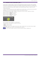
3. Control Components 3.2. Input (Normalized Value): Button Switching the Button’s on/off state causes output of the specified value (normalized value). (For 2 inputs) INPUT On1: Input value to control the channel 1 button (OFF:0, ON:1) On2: Input value to control the channel 2 button (OFF:0, ON:1) OUTPUT On1: Outputs the channel 1 setting value (0.00–1.00) On2: Outputs the channel 2 setting value (0.00–1.00) The button turns off when 0 is input from the input port, and turns on when 1 is input. 3.2.1.
3. Control Components 3.3. Input (Value): Button Switching the button’s on/off state causes output of the specified value. The type of output value (Num or dB) can be selected in the dialog that is displayed when the component is placed. (For 2 inputs) INPUT On1: Input value to control the channel 1 button (OFF:0, ON:1) On2: Input value to control the channel 2 button (OFF:0, ON:1) OUTPUT On1: Outputs the channel 1 setting value (–20,000 to 20,000), (−∞ to 10.
3. Control Components 3.3.2. ”Button” component editor (dB) ① When the button is switched on, the value set in ② is output, and when the button is switched off, the value set in ③ is output. ② −∞ to 10.00 ③ −∞ to 10.00 Parameter types of the input/output values for each Port Operation Output Value Input Port Name Trigger/Proces Output Port sing Name Type ● On1 Trigger: Button ● On1 Value Range dB −∞–10.
3. Control Components 3.4. Input (Normalized Value): Radio Button Only one of multiple buttons can be turned on. All buttons can be turned off. When a button is switched to on, the channel number of the button that turned on and the specified value (normalized value) are output.
3. Control Components Parameter types of the input/output values for each Port Operation Output Value Input Port Name Trigger/Proces Output Port sing Name Type Range ● CH (1,2..) Trigger: Radio Button ● CH (1,2..) Normalized OFF:0, ON:1 - ● Out Value Num 0.00–1.00 ● Sel ● Sel Value Num 1–256 * Input Port: It is also possible to control the ON button by inputting OFF:0 and ON:1 in the Value (Num) data type for CH.
3. Control Components 3.5. Input (Value): Radio Button Only one of multiple buttons can be turned on. All buttons can be turned off. When a button is switched to on, the channel number of the button that turned on and the specified value are output. The type of output value (Num or dB) can be selected in the dialog that is displayed when the component is placed.
3. Control Components 3.5.2. ”Radio Button” component editor (dB) ① When the button is switched on, the value set in ② is output. ② −∞ to 10 dB ③ Displays the channel number for which the button has turned on. If all of them are off, "0" will be displayed. Parameter types of the input/output values for each Port Operation Output Value Input Port Name Trigger/Proces Output Port sing Name Type ● CH (1,2..) Trigger: Radio Button ● CH (1,2..) Value Num OFF:0 ON:1 ● Out Value dB −∞–10.
3. Control Components 3.6. Input (Normalized Value): Fader Continuous values (normalized values) are output by adjusting the controller. (For 2 inputs) INPUT Value 1: Input value to control knob 1 (0.00–1.00) Value 2: Input value to control knob 2 (0.00–1.00) OUTPUT Value 1: Output value when knob 1 is operated (0.00–1.00) Value 2: Output value when knob 2 is operated (0.00–1.00) The knob can also be controlled by an input signal (0.00–1.00). 3.6.1.
3. Control Components 3.7. Input (Value): Fader Continuous values are output by adjusting the controller. The type of output value (Num or dB) can be selected in the dialog that is displayed when the component is placed. (For 2 inputs) INPUT Value1: Input value to control knob 1 (–20,000 to 20,000), (−∞ to 10.00) Value2: Input value to control knob 2 (–20,000 to 20,000), (−∞ to 10.00) OUTPUT Value1: Output value when knob 1 is operated (–20,000 to 20,000), (−∞ to 10.
3. Control Components 3.7.2. ”Fader” component editor (dB) ① Outputs a value of −∞ to 10.00. ② MAX and MIN specify the fader operation range (−∞ to 10.00). Parameter types of the input/output values for each Port Operation Output Value Input Port Name Trigger/Proces Output Port sing Name Type ● Value1 Trigger: Fader Value ● Value1 Range Num -20000–20000 dB ∞–10.00 Num -20000–20000 dB −∞–10.
3. Control Components 3.8. Processing (Normalized Value): Logic This is the basic circuit component. AND, NAND, OR, NOR, XOR, NOT XOR or 1 of N can be selected in the dialog that is displayed when the component is placed. (For 2 inputs) INPUT 1: Input value 1 to Logic (OFF:0, ON:1) 2: Input value 2 to Logic (OFF:0, ON:1) OUTPUT Out: Logic process results (OFF:0, ON:1) 3.8.1. ”Logic” component editor ① Input signals can be checked. ② Output signals (process results) can be checked. 3.8.2.
3. Control Components 3.8.4. ”Logic” component editor (OR) When all of the inputs are 0, then the output is 0. If any 1 of the inputs is 1, then the output is 1. If the input and output are 0, the indicator is off, and if the input and output are 1, the indicator is on. 3.8.5. ”Logic” component editor (NOR) When all of the inputs are 0, then the output is 1. If any 1 of the inputs is 1, then the output is 0.
3. Control Components 3.9. Processing (Normalized Value): NOT This component inverts the input value. INPUT 1: Input value (OFF:0, ON:1) OUTPUT Out1: NOT process results (OFF:0, ON:1) If the input value is 1, then the output is 0. If the input value is 0, then the output is 1. 3.9.1. ”NOT” component editor ① On when the input value is 1, off when the input value is 0. ② On when the output value is 1, off when the output value is 0.
3. Control Components 3.10. Processing (Normalized Value): Flip-Flop This component is used to enable toggle operation. INPUT Set: Trigger input to push the [Set] button* Reset: Trigger input to push the [Reset] button* Toggle: Trigger input to push the [Toggle] button* *: Values that are input from an external source act as simple triggers that are not related to any operation.
3.
3. Control Components 3.11. Processing (Normalized Value): Invert This component calculates the maximum value of the normalized value (1.00) minus the input value. (For 2 inputs) INPUT 1: Channel 1 input value (0.00–1.00) 2: Channel 2 input value (0.00–1.00) OUTPUT Out1: 1.00 minus the channel 1 input value Out2: 1.00 minus the channel 2 input value 3.11.1. ”Invert” component editor ① The input value (0.00–1.00) can be checked. ② 1.00 minus the input value ① is output as the value.
3. Control Components 3.12. Processing (Normalized Value): Compare This component is used to obtain the result of comparing two input values. Greater, Less or Equal can be selected in the dialog that is displayed when the component is placed. INPUT 1: Input value 1 (0.00–1.00) 2: Input value 2 (0.00–1.00) OUTPUT Out: Comparison result (0, 1) 3.12.1. ”Compare” component editor ① Input values can be checked. (0.00–1.00) ② Outputs the result of comparing two input values. 3.12.2.
3. Control Components Parameter types of the input/output values for each Port Input Value Operation Type Range Normalized 0.00–1.
3. Control Components 3.13. Processing (Normalized Value): Difference This component is used to obtain the difference between two input values. INPUT 1: Input value 1 (0.00–1.00) 2: Input value 2 (0.00–1.00) OUTPUT Out: The value of input 1 minus input 2 If the result of subtracting input value 2 from input value 1 is negative (minus), the result is 0.00. 3.13.1. ”Difference” component editor ① The input value (0.00–1.00) can be checked.
3. Control Components 3.14. Processing (Normalized Value): Max/Min This component detects and outputs the largest/smallest value of the values input from multiple ports. (For 2 inputs) INPUT 1: Input value 1 (0.00–1.00) 2: Input value 2 (0.00–1.00) OUTPUT Max: The largest value from multiple input values (0.00–1.00) Min: The smallest value from multiple input values (0.00–1.00) 3.14.1. ”Max/Min” component editor ① The input value (0.00–1.00) can be checked. ② The largest value (0.00 to 1.
3. Control Components 3.15. Processing (Value): Negate This component performs arithmetic operations on input values. Negate, Square, Square Root or Absolute can be selected in the dialog that is displayed when the component is placed. (For 2 inputs) INPUT 1: Channel 1 input value (–20,000 to 20,000), (−∞ to 10.00) 2: Channel 2 input value (–20,000 to 20,000), (−∞ to 10.00) OUTPUT 1: Calculation results for channel 1 input values 2: Calculation results for channel 2 input values 3.15.1.
3. Control Components Parameter types of the input/output values for each Port Input Value Operation Type Value Range Input Port Name Num -20000–20 ● CH 000 (1,2..) dB −∞–10.00 Output Value Trigger/Pr Output Type ocessing Port Name Processing : Negate, Square, Square Root, Absolute ● CH (1,2..
3. Control Components 3.16. Processing (Value): Compare This component is used to obtain the result of comparing two input values. Greater, Less or Equal can be selected in the dialog that is displayed when the component is placed. INPUT 1: Input value 1 (–20,000 to 20,000), (−∞ to 10.00) 2: Input value 2 (–20,000 to 20,000), (−∞ to 10.00) OUTPUT Out: Comparison result (0, 1) 3.16.1. ”Compare” component editor ① Input values can be checked. ② Outputs the result of comparing two input values. 3.16.2.
3. Control Components Parameter types of the input/output values for each Port Input Value Type Value - Operation Range Input Port Name Num -20000–2 ● CH 0000 (1,2..) dB −∞–10.
3. Control Components 3.17. Processing (Value): Multi Compare This component compares the input values from multiple ports and detects the channel number with the largest/smallest input value. Greatest or Smallest can be selected in the dialog that is displayed when the component is placed. (For 2 inputs) INPUT 1: Input value 1 (–20,000 to 20,000), (−∞ to 10.00) 2: Input value 2 (–20,000 to 20,000), (−∞ to 10.00) OUTPUT Out 1: Outputs ON:1 when the channel 1 input value is the largest/smallest value.
3. Control Components Parameter types of the input/output values for each Port Input Value Type Value Operation Range Input Port Name Num -20000–2 ● CH 0000 (1,2..) dB −∞–10.00 Output Value Trigger/P Output rocessing Port Name Type Processin ● CH g : Multi (1,2..
3. Control Components 3.18. Processing (Value): Difference This component is used to obtain the difference between two input values. INPUT 1: Input value 1 (–20,000 to 20,000), (−∞ to 10.00) 2: Input value 2 (–20,000 to 20,000), (−∞ to 10.00) OUTPUT Out: The value of input 1 minus input 2 If the result of subtracting input value 2 from input value 1 is negative (minus), the result is 0.00. 3.18.1. “Difference” component editor ① Input signals can be checked.
3. Control Components 3.19. Processing (Value): Max/Min This component detects and outputs the largest/smallest value of the values input from multiple ports. (For 2 inputs) INPUT 1: Input value 1 (–20,000 to 20,000), (−∞ to 10.00) 2: Input value 2 (–20,000 to 20,000), (−∞ to 10.00) OUTPUT Max: The largest value from multiple input values Min: The smallest value from multiple input values 3.19.1. ”Max/Min” component editor ① The input value (0.00–1.00) can be checked.
3. Control Components 3.20. Processing: Delay This component can delay the input signal before outputting it.
3. Control Components Parameter types of the input/output values for each Port Input Value Type Operation Range Through Value Num OFF:0, ON:1 Output Value Input Port Name Trigger/P Output rocessing Port Name Type ● CH (1,2..) Processin ● CH g: Delay (1,2..) Same value as the Input Value ● ON (1,2..) ● ON (1,2..
3. Control Components 3.21. Processing: External Events Configures the command to send to the network using the input of 0 or 1 to an input port as a trigger. One External event can be set for 1 input port. A maximum of 16 External events can be set within a component. The protocol (TCP, UDP) can be selected in the dialog that is displayed when the component is placed. 3.21.1. ”External Events” component editor ① [IP Address] text box Sets the IP address for the device that will receive the command.
3. Control Components ④ [Port] list box Selects the target for editing. ⑤ [Comment] text box Allows for input of text. For example, it can be used to enter a description of an event to make it easier to identify. ⑥ [Command] button When 0 is selected, the command that will be sent when 0 is input to the input port will be edited in the [Hex] text box. When 1 is selected, the command that will be sent when 1 is input to the input port will be edited in the [Hex] text box.
3. Control Components 3.22. Processing: Suspend This is a control component to temporarily stop the output of the input signal.
3. Control Components 3.23. Processing: Router Assigns an input to an output port. One input can be output to multiple channels, but multiple inputs cannot be output to a single channel. (For 2 inputs) INPUT 1: Input value to channel 1 2: Input value to channel 2 Out1 In1: Switches the output of In1 to Out1 (OFF:0, ON:1) (*) Out1 In2: Switches the output of In2 to Out1 (OFF:0, ON:1) (*) Out1 Sel: Specifies the input signal output to Out1 (0–64) (*) The signal is not output if 0 is specified.
3. Control Components 3.23.1. ”Router” component editor ① This is the router that distributes inputs signals. Clicking on a square toggles the output on or off. Parameter types of the input/output values for each Port Input Value Type Operation Range Through Output Value Input Port Name Trigger/P Output rocessing Port Name Type ● CH (1,2..) Processin ● CH g: Router (1,2..) Input Valueと同じ値 Value Num OFF:0, ON:1 ● OUT (1,2..) (In1,2..) Value Num INPUT CH ● OUT No (1,2..
3. Control Components 3.24. Controller: GPI In Converts signals input from GPI IN into control signals that can be handled by the Control layer. For the input from each GPI In connector (16 connectors), a continuous value (normalized from 0 to 1) is output from each output port. There are two GPI Input setting methods. • Configure the settings in the GPI Input dialog that opens from the [Tools] button on the device sheet.
3. Control Components 3.24.1. ”GPI Input” component editor The input GPI signal is converted to a normalized value (0 to 1) using the specified method, and is then output. Refer to the GPI Input dialog in the ProVisionaire Design User Guide for the rest. Parameter types of the input/output values for each Port Input Value Operation Type - - Output Value Range Input Port Name Trigger/Pr Output Type ocessing Port Name - - Trigger: GPI IN 160 | ProVisionaire Design Component Guide ● CH (1,2..
3. Control Components 3.25. Controller: GPI Out Outputs the GPI Out signal from the GPI Out connector. There are two GPI Output setting methods. • Configure the settings in the GPI Output dialog that opens from the [Tools] button on the device sheet. Try this method if you are using one operation as a trigger and outputting from a single [GPI OUT] connector. • Add the GPI Output component to the Control layer of the device sheet and set it using in the Component Editor.
3. Control Components 3.25.1. ”GPI Output” component editor Refer to the GPI Input dialog in the ProVisionaire Design User Guide for the rest. Parameter types of the input/output values for each Port Input Value Operation Type Value Num Output Value Range Input Port Name Trigger/Pr Output Type ocessing Port Name Range OFF:0, ON:1 ● CH (1,2..
3. Control Components 3.26. Controller: Scheduler Outputs a trigger at the time the event is activated. INPUT Enable 001: Controls the event’s ”Enable” parameter (OFF:0, ON:1). OUTPUT Event 001: Outputs 1 at the time the event activates 3.26.1. “Scheduler” component editor ① [Add] button Opens the “Add Event” dialog. ② [Edit] button Opens the selected event’s edit dialog. See the Add Event dialog for a description of the setting items.
3. Control Components ⑤ [Show Event Tim] check box When this check box is empty (off), the event occurrence time is not displayed. This is to save display space. ⑥ Event Info Displays a summary of the currently selected event. ⑦ [<][>] buttons For Month, this advances/returns the display by one month. For Day, this advances/returns the display by one day. ⑧ [Today] button In Month view, this jumps to the month that includes today. For the Day view, this display today’s schedule.
3. Control Components 3.26.2. “Add Event” dialog box You can add an event here. One-time events or recurring events can be configured. ① [No.] text box Specifies the output terminal of the component issuing the event. This can be changed after setting. ② [Event Name] text box Shows or edits the event name. ③ Event Schedule • [Color] selection button Selects the color for events displayed on the calendar. Using this to color-code events makes them easier to see and differentiate.
3. Control Components If Repeat Event below is checked and the event interval is set to "Hourly", only minutes can be set. To manage time under 1 minute, connect a Delay control component to the component’s output terminal and adjust the time there. ④ Repeat Event • [Repeat Event] check box By selecting this check box you can specify a repeating event.
3. Control Components 3.27. Parameter Set Recalls a snapshot when there is an input on the input port. For information on how to add components to the control layer, refer to "Controlling a Snapshot and ParamSet in the control component" in the user guide.
3. Control Components 3.28. Snapshot Recalls a snapshot triggered by an input. Refer to "Controlling a Snapshot and ParamSet in the control component" in the user guide for information on adding components to the control layer.
© 2023 Yamaha Corporation Published 01/2024 YJHH-B0