
User Manual

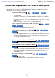
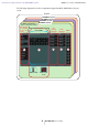
Table Of Contents
- Notice regarding data copyright
- Notice regarding the content of this user guide
- Contents
- Chapter 1. An overview of MTX-MRX Editor
- An audio system control network
- Terms used in this user guide
- Data handled by MTX-MRX Editor
- Connection requirements for an MTX/MRX system
- MTX/MRX system configuration examples
- What are YDIF connections? (Cascade mode and Distribution mode)
- What are Dante connections? (Daisy-chain connection and Star connection)
- Patching
- Workflow
- About the screens
- Moving between screens
- Chapter 2. Menu bar and tool buttons
- Chapter 3. Project screen
- Chapter 4. System screen
- Chapter 5. Online and Synchronization
- Chapter 6. Presets
- Chapter 7. Dialog boxes/Software applications
- “Startup” dialog box
- “Network Setup” dialog box
- “Device Information” dialog box
- “Match Device by IP Address” dialog box
- “MTX Configuration” dialog box
- “Dante Information” dialog box
- “Word Clock” dialog box
- “Clock” dialog box
- “Daylight Saving Time” dialog box
- “Scheduler” dialog box
- “Remote Control” dialog box
- “External Events” dialog box
- “Digital Control Panel” dialog box
- “Wireless DCP” dialog box
- “MCP1” dialog box
- “PIN Setup” dialog box
- “Label” dialog box
- “Re-size Image” dialog box
- “PGM1/PGX1” dialog box
- “PGM1 Label Creator” application
- “GPI” dialog box
- “GPI Calibration” dialog box
- “Security Settings” dialog box
- “Project Information” dialog box
- “Configuration Diagram” dialog box
- “Get Log” dialog box
- “Sampling Rate Converter” dialog box
- “Input Source/Redundant” dialog box
- Appendix

Connection requirements for an MTX/MRX system Chapter 1. An overview of MTX-MRX Editor
MTX-MRX Editor User Guide
7
Connection requirements for an MTX/MRX system
The requirements for an MTX/MRX system are as follows.
A maximum of 80 devices such as MTX/MRX/EXi/EXo/XMV/R series (AD/DA)/Tio1608-D/
MCP1/PGM1 units can belong to one project.
Overall MTX/MRX system (1 in diagram below)
• The XMV/R series (AD/DA)/Tio1608-D is controlled from MTX-MRX Editor via
the MTX/MRX
•
A maximum of 20 devices such as MTX/MRX/EXi/EXo/XMV/R series (AD/DA)/
Tio1608-D units can belong to one MTX/MRX system
• A maximum total of 20 devices such as PGM1/MCP1 units can belong to one MTX/
MRX system
• Only one computer at a time can access the MTX/MRX system
Devices connected to each other via YDIF connection (
2 in dia-
gram below
)
• Maximum total of eight units (maximum of four MTX/MRX units)
• At least one MTX/MRX unit must be included
Control panels connected to the
MTX/MRX
(3 in diagram
below)
• For each MTX/MRX unit, there can be a maximum of eight digital control panels
(DCP) belonging to the MTX/MRX system
• For each MTX/MRX unit, there can be a maximum of eight wireless DCP units
belonging to the MTX/MRX system
• A maximum of four PGM1 units can belong to one MTX/MRX system
XMV connected via analog to the MTX/MRX (4 in diagram
below)
•
A maximum of 20 units for the entire MTX/MRX system, including the XMV units included here
Devices connected to the MTX/MRX via Dante (5 in diagram
below)
• A maximum of 20 units for the entire MTX/MRX system, including the XMV units
included here
• A maximum of eight R series (AD/DA) and Tio1608-D units can belong to one
MTX/MRX system
MCP1 units connected to the MTX/MRX (6 in diagram
below)
• Up to a total of 16 units
• All MTX/MRX units within the MTX/MRX system can be controlled