MRX Designer User Guide This user guide explains “MRX Designer,” which is part of the “MTX-MRX Editor” Windows application and which allows you to make settings for the MRX7-D (subsequently referred to as the MRX). For an explanation of MTX-MRX Editor topics that are not part of MRX Designer, refer to “MTX-MRX Editor User Guide.” In this user guide, < > indicates a key on the computer keyboard. indicates the Shift key.
Contents An overview of MRX Designer ............................................................6 Screen structure..................................................................................7 Basic use of MRX Designer..................................................................9 Menu bar...........................................................................................12 Tool buttons .....................................................................................17 Shortcut keys ...
Contents Components and the component editor ..........................................43 ❏ Editing the parameters ................................................................................ 44 Knobs........................................................................................................................44 Sliders .......................................................................................................................44 Buttons ..............................................
Contents “STEREO IN” editor ................................................................................................86 “YDIF IN” editor .....................................................................................................86 “SLOT IN” editor .....................................................................................................87 “ANALOG OUT” editor ..........................................................................................87 “DANTE OUT” editor ..........
Contents Dialog boxes and applications........................................................119 ❏ “Print” dialog box ......................................................................................119 ❏ “Install Speech Privacy File” dialog box ....................................................120 ❏ “File Transfer” application .........................................................................122 ❏ “PGM1 Label Creator” application ............................................................
An overview of MRX Designer An overview of MRX Designer The MRX is a freely configurable processor that allows you to place components as desired to freely design a system. The MRX can be operated from an external controller such as a DCP, Wireless DCP, or MCP1. Using the PGM1 allows a paging system to be constructed. MRX Designer is dedicated software for configuring the MRX. In MRX Designer, your workflow consists of freely placing Components in Design sheet and then Compile the result.
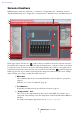
Screen structure Screen structure MRX Designer consists of a “menu bar,” “tool buttons,” “Components area,” “Parameter Sets area,” “Parameter Link Group area,” “design sheet,” “Properties area,” “Parameters area,” and “Bird’s Eye view.” 7 1 2 A 8 3 B 9 0 4 5 6 In the upper right of each area is a “ ” symbol; when you click this, the area becomes an icon and is placed at the left or right side of the screen, allowing the design sheet to occupy more of the screen.
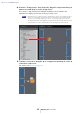
Screen structure 4 “Parameter Sets” area In this screen you can create parameter sets for each system, and store or recall snapshots. From the design sheet, call up the component editor. While holding down , drag the parameter that you want to register and drop it on the parameter set name in the “Parameter Sets” area; the parameter is registered in the parameter set. Snapshots can also be created in this area.
Basic use of MRX Designer Basic use of MRX Designer The basic workflow in MRX Designer is described below. 1. Register the MRX in the “Device Configuration Wizard.” The “Device Configuration Wizard” appears when you click the [Device Config] button, etc. Register other devices as necessary. 2. In the System screen, select MRX7-D. 3. Click the “Open MRX Designer” button. The MRX Designer window opens.
Basic use of MRX Designer 4. From the “Components” area at the left, drag the component that you want to use and drop it on the design sheet. If you drop a component that has multiple candidates such as channels, the candidates are displayed; select the one that you want to use. NOTE • Double-click on a component in the “Components” area to select Stamp mode; in this mode, components are placed successively each time you click the design sheet.
Basic use of MRX Designer 6. Double-click a component or right-click it and choose “Open Component Editor”; the component editor opens, allowing you to operate the parameters. 7. When you have made the necessary settings, click the “Compile” button to check whether there are any problems with the placement and connections of the component. The steps up to this point can be performed beforehand using MRX Designer. To make connections with other equipment, you’ll use the “EXT.
Menu bar Menu bar The commands that can be executed in MTX Editor can be found here, grouped by category. Click here to see a list of commands. Menu [File] Command Summary Dialog box or window that appears [Save] Saves the MTX-MRX Editor project file (overwriting the previous version of the file). “Save File” dialog box The first time you save, the “Save File” dialog box will appear; specify a name for the file and save it.
Menu bar Menu Command Summary Dialog box or window that appears [Undo] Cancels the preceding operation.*1 — [Redo] Re-executes the operation that was canceled by [Undo]. *1 — [Cut] Moves the selected item to the copy buffer. — [Copy] Copies the selected item to the copy buffer. The copied component etc. can be pasted into drawing software such as Paint. — [Paste] Pastes the item from the copy buffer.
Menu bar Menu Command Dialog box or window that appears [Components] — [Parameter Sets] — [Parameter Link Group] [Gang Edit Group] [View] Summary If this item has a check mark, the corresponding area is shown. — — [Properties] — [Parameters] — [Bird’s Eye View] Selects the Bird’s Eye view display type. [Floating] : Shows the Bird’s Eye view in a separate window from MRX Designer. [Docking] : Shows the Bird’s Eye view in the lower right of MRX Designer. [Hide] : Hides the Bird’s Eye view.
Menu bar Menu Command Summary [External Events] Enables you to configure the commands to be transmitted so that you can control peripheral devices via the network to which the Dante connector or NETWORK connector is connected. For details, refer to “MTX-MRX Editor User Guide.” “External Events” dialog box [GPI] Lets you make settings for the GPI connector of the MRX. For details, refer to “MTX-MRX Editor User Guide.” “GPI” dialog box Lets you make settings for a DCP.
Menu bar Menu [Window] [Help] Command Summary Dialog box or window that appears [Close All Editor Windows] Closes all component editor and parameter setting windows. — [Show All Editor Windows] Shows all component editor and parameter setting windows in the foreground. — [Hide All Editor Windows] Hides all component editor and parameter setting windows. — [Show MTXMRX Editor] Shows MTX-MRX Editor in the foreground. — [Shortcut Keys] Shows a list of shortcut keys.
Tool buttons Tool buttons Commands frequently used in MRX Designer, such as “Compile” and “Align Left Side,” are provided as buttons. Button Command Summary [Show MTX-MRX Editor] Shows “MTX-MRX Editor” in the foreground. [Print] Prints the design sheet. [Undo] Cancels the preceding operation.*1 [Redo] Re-executes the operation that was canceled by [Undo]. *1 [Cut] Moves the selected item to the copy buffer. [Copy] Copies the selected item to the copy buffer.
Shortcut keys Shortcut keys Here are the shortcut keys that you can use in MRX Designer. Key combinations Operation < > / +< > Scrolls the design sheet upward. If a component is selected, this moves the selected component upward. < > / +< > Scrolls the design sheet downward. If a component is selected, this moves the selected component downward. < > / +< > Scrolls the design sheet to the left. If a component is selected, this moves the selected component to the left.
Shortcut keys Key combinations Operation + + drag the mouse cursor Selects the input ports and output ports of the components that are completely enclosed by the rectangular area in the design sheet. Double-click a component in the “Components” area Initiates Stamp mode. Stamp mode is a function that places a component on the design sheet each time you click. Exits Stamp mode or editing.
Design sheet Design sheet Here you can place components and connect them. Parameter settings are the main operations that you can perform while online. Operations such as placing and connecting components can only be done while offline. ❑ Placing components Here we explain how to place components on the design sheet. NOTE If any component in the “Components” area is selected, pressing an alphabetical key will select the component of the matching initial letter.
Selecting multiple components, ports, or wires ❑ Selecting multiple components, ports, or wires Here’s how to select multiple components placed in the design sheet, or multiple wires that connect ports of components. • Use the mouse cursor to completely enclose objects Drag the mouse cursor to select the components, component ports, wires, and text that are completely enclosed by the rectangular area in the design sheet.
Selecting multiple components, ports, or wires • Hold down and click objects Hold down and click the target that you want to select. If you hold down and click an object that is already selected, the selection is cleared. This is convenient when you have selected multiple objects by enclosing them, and then want to de-select one of the selected objects.
Connecting ports ❑ Connecting ports Here we explain how to make connections between ports of components by creating a wire between the ports. • Making one connection at a time Drag one output port to the input port of the destination component. • Making multiple connections at a time Select multiple output ports, and drag one of these ports to an input port of the destination component.
Tracing the signal path ❑ Tracing the signal path Here we explain how to view the signal path. To view the signal path, add a check mark to the [Tools] menu →[Trace Signal Path] command. • Click a wire The path of the signal flowing through that wire is shown. • Click a port The path of the signal flowing through that port is shown. If the signal path is connected but no audio signal flows because it is turned OFF or the level is minimized, the signal path is shown as a dashed line.
Duplicating an input port name ❑ Duplicating an input port name If you want to use the signal name as the port name, it is convenient to duplicate the port name. Here we explain how to automatically duplicate the input port name. In general, the input port name is automatically duplicated to the input port of the connectiondestination component, but the following exceptions apply.
About [Unbundle Wires] ❑ About [Unbundle Wires] After you have placed all of the necessary components and have finished creating wires between them, you can select all components and execute [Unbundle Wires] to prevent the wires from overlapping in the display. When you execute [Unbundle Wires], the items in the “Properties” area for the components and the wires connected to the components are set to the following values.
YDIF handling ❑ YDIF handling In an MTX/MRX system that uses YDIF to transmit or receive audio signals, you’ll need to make connections by placing YDIF IN and YDIF OUT components on the MRX. If these connections are not made, the YDIF signal might be disconnected inside the MRX, causing the sound to no longer be output. If you’re not performing signal processing inside the MRX, connect the inputs directly to the outputs as shown in the diagram below.
Duplicating components ❑ Duplicating components Here we explain how to duplicate components together with their parameters. • Right-click a component and choose [Duplicate] A duplicate, overlapping component is created. If multiple components with their wires are selected when you choose [Duplicate], the components are duplicated together with their wires. • Drag and drop a component while holding down A duplicate is created where you drop the component.
“Parameter Sets” area “Parameter Sets” area A set of parameters stored or recalled as a snapshot is called a “parameter set.” You can create such a parameter set, register the desired parameters of the MRX to the parameter set, and store the current values of the parameter set members as a snapshot. One parameter set can store up to 10 different snapshots. A parameter can be registered in more than one parameter set. Parameters can be registered in a parameter set in the following ways.
“Parameter Sets” area 2 3 1 4 5 6 7 8 9 0 A If you place the cursor on the border between Parameter Sets and Snapshot, the cursor changes shape, letting you drag to change the height of Snapshot. 1 [New] button Creates a new parameter set. 2 [Add Device] button Registers an individual device to the parameter set. NOTE Even if you register an entire device, the Link Master settings of the parameter link group are not included.
“Parameter Sets” area 4 [Duplicate] button Duplicates the selected parameter set. If you want to duplicate the snapshots as well, add a check mark to [Duplicate Snapshots Also] in the “Duplicate” dialog box that appears. 5 [+]/[–] buttons Completely expands or completely minimizes the parameter set display. 6 Parameter set name Shows the name of the parameter set. You can double-click the parameter set name and edit it.
“Preset” dialog box ❑ “Preset” dialog box If you register a snapshot in a preset, it can be recalled together with devices such as the MTX, XMV, and DCP. To store all of the parameters of the MRX units included in the MTX/MRX system, store the preset by pressing the [Store] button in the “Preset” dialog box. The parameters are linked to the preset as [All Parameters]. However if you want to change only some of the parameters of the MRX, replace [All Parameter] with a snapshot.
“Preset” dialog box 1 2 3 1 Preset recall method selection buttons Depending on the selection here, preset recall will operate as follows. No Assign : The corresponding preset will not recall the parameters of the MRX. All Parameters : The corresponding preset will control all parameters (including all Link Master settings) of the MRX. Snapshot / Snapshot Group : The corresponding preset will recall a snapshot or multiple snapshots (a snapshot group).
“Preset” dialog box Using a preset to recall only one snapshot Open the [Snapshot] tab. Select the snapshot that you want to recall, and click the [OK] button.
“Preset” dialog box Using a preset to recall multiple snapshots 3 4 2 1 5 6 7 8 Open the [Snapshot Group] tab. 1 [New] button Opens the “New Snapshot Group” dialog box, allowing you to create a new snapshot group. 2 [Edit] button Opens the “Edit Snapshot Group” dialog box, allowing you to edit the selected snapshot group. The procedure is the same as in the “New Snapshot Group” dialog box.
“New Snapshot Group” dialog box “New Snapshot Group” dialog box A snapshot group recalls multiple snapshots in succession. A created snapshot group can be used with a preset, scheduler, GPI, DCP, Wireless DCP, or Remote Control Setup List. In this dialog box you can select a snapshot and register it in the snapshot group or delete it. 1 3 5 2 6 4 7 8 1 “Group Name” Shows the name of the snapshot group. You can select the displayed name and edit it.
“Parameter Link Group” area “Parameter Link Group” area You can create a parameter link group that links multiple parameters such as Level or ON/OFF. The parameters of multiple MRX units within the MTX/MRX system can be registered in a single parameter link group. A single parameter can also be registered in more than one parameter link group. A created parameter link group can be used with a snapshot, scheduler, GPI, DCP, Wireless DCP, or Remote Control Setup List.
Link Master editor ❑ Link Master editor There is a link master for each parameter link group. When you change a link master parameter, the change also affects the parameters that are registered to the parameter link group. Even if you change a parameter that is registered to the parameter link group, the change does not affect the link master parameters. The name of the parameter link group is shown in the title bar and at the bottom of the editor.
“Gang Edit Group” area “Gang Edit Group” area In this area you can create gang edit groups that link multiple components. Components of multiple MRX units within a MTX/MRX system can be registered in a single gang edit group. This lets you simultaneously modify the parameters of similar components within a group. Since this can be done even when offline, you can use it to make final adjustments to (for example) the Speaker Processor while listening to the sound at the actual location.
“Gang Edit Group” area 1 [Active] button Enables/disables the gang edit group function. This applies to the currently selected group. 2 [New] button Creates a new gang edit group. 3 [Delete] button Deletes the selected gang edit group or component. 4 [+]/[?] buttons Completely expands or completely minimizes the gang edit group display. 5 [Parameters] check box Select the check box for parameters that you want to link. The actual procedure is described below. 1. Click the [New] button. 2.
“Properties” area “Properties” area In this area you can view and edit information for the currently-selected component, port, wire, or design sheet. Click the property Form field to make the [...] appear, and click it to select the desired number of channels. This cannot be changed on a component for which [...] is not shown. 1 2 3 1 Display select buttons These buttons select whether user style items are shown by category ( alphabetical order ( ).
“Properties” area 3 Properties This area shows information about the currently-selected component, port, wire, or design sheet. Click an item at the right to edit the information. You can select multiple items of the same type and edit them simultaneously. NOTE • The Component Type and ID cannot be edited. • If multiple items are selected, the information of the last-selected item is shown.
Components and the component editor Components and the component editor Here we explain components, the component editor, and the dialog boxes and windows that are closely related to components. For components that differ in the number of inputs and outputs, the illustration shows the most typical model. When you double-click a component in the design sheet, the component editor opens.
Editing the parameters ❑ Editing the parameters Here we explain how to set the parameters in the component editor. Knobs There are several ways to edit a knob parameter. • Select the knob, hold down the left mouse button, and move the mouse cursor up or down. • Select the knob and turn the mouse wheel. • Select the numeric display area, hold down the left mouse button, and move the mouse cursor up or down. • Select the numeric display area and turn the mouse wheel.
Buttons • Opening a parameter setting window or another component editor Click the button to open a parameter setting window or another component editor. • Displaying a menu Click the button to access a menu.
Acoustic Echo Canceller (AEC) ❑ Acoustic Echo Canceller (AEC) Acoustic Echo Canceller (AEC) is a function that eliminates the acoustic echo that can be a problem during remote conferencing when sound from a speaker is picked up by microphones or reflected from a wall, or steady-state noise such as produced by air conditioning systems. By providing the other party with clear audio from which such echo and noise have been removed, conversation during the remote conference can be conducted smoothly.
Acoustic Echo Canceller (AEC) 2 [NR] button This is an on/off switch for the noise reduction function which removes steady-state noise such as produced by a projector or air conditioner in the local location. We recommend that you leave this on. 3 [THRESHOLD] knob When applying noise reduction, noise that exceeds the Threshold level is attenuated down to the level specified by Threshold. 4 Level meters These show the input/output levels and information related to acoustic echo.
Ambient Noise Compensator (ANC) ❑ Ambient Noise Compensator (ANC) ANC (Ambient Noise Compensator) is a function that boosts or attenuates the level of the program source according to the level that is being input via an ambient noise detection mic. The ANC function provided by the MTX is a gap-type ANC that detects silent intervals such as between songs, detects the noise level during those intervals, and varies the level accordingly.
“Ambient Noise Compensator” editor “Ambient Noise Compensator” editor Here you can make settings related to ANC. 1 2 3 4 Program source input level Gap Threshold Gap Time Gap Time Gap Gap Time Ambient noise level Higher Sense Threshold Program source compensation amount Lower Time Response Time Response Time Max. Gain Time Min. Gain 1 ANC [ON] button Switches the ANC function between enabled and disabled. 2 AMIBIENT • Level meter Shows the level of ambient noise.
“Ambient Noise Compensator” editor 3 GAP • [THRESHOLD] knob Specifies the threshold value of the program source. If the level of the program source remains below the threshold for a specified time, it will be interpreted as a gap. • [TIME] knob Specifies the time required for a gap to be detected. 4 PROGRAM SOURCE GAIN • [MIN GAIN] knob Specifies the minimum value of program source level compensation. • [MAX GAIN] knob Specifies the maximum value of program source level compensation.
Audio Detector ❑ Audio Detector Audio Detector is a function that detects audio signals. By registering the detection indicator to the GPI Output, a signal can be output from the unit's GPI [OUT] connector when an audio signal is detected. “Audio Detector” editor Here you can specify the threshold value of the audio signal, and see whether an input exceeding the threshold value has been detected. 1 2 3 4 1 Detection indicator Lights when an input exceeding the threshold value is detected.
Auto Gain Controller (AGC) ❑ Auto Gain Controller (AGC) AGC (Auto Gain Controller) is a function that automatically compensates the gain according to the input level, keeping a constant output level for an incoming signal whose level is changing. For example, differences in how closely and how loudly a person is speaking into a mic can make their amplified voice vary in volume, making it less intelligible. In such cases, the volume will be automatically adjusted within a fixed range.
“Auto Gain Controller” editor Compensation Level Threshold Ratio 1 -21 2 -27.75 1 1.3 3 -34.5 2 4 -41.
Combiner ❑ Combiner This function is used when audio signals are shared between multiple rooms, or when a single room is partitioned in varying ways. The audio signal outputs are changed according to how the rooms are divided or connected. The MRX provides two types of combiner: “Room Combiner” and “Room Combiner plus Automixer.” The latter adds Dan Dugan Automixer functionality. Up to eight rooms can be registered in the combiner, and you can also specify the shape of the rooms as their actual shape.
Combiner If you want to reassign the room numbers, click the room numbers consecutively. During editing, if you want to renumber the rooms starting from 1, click the [Restart numbering] button. After you have finished renumbering, click the [Next>] button. The screen changes to a screen where you can specify the number of mics placed in the rooms.
Combiner In the dropdown list, select the number of mics used by all rooms, and click or drag the cells of the mics to be assigned to the rooms. After you have finished making assignments, click the [Create] button. “Room Combiner plus Automixer” is placed in the design sheet. “Room Combiner” does not have this screen. The inputs are assigned as follows, starting from the top.
“Room Combiner” editor / “Room Combiner plus Automixer” editor “Room Combiner” editor / “Room Combiner plus Automixer” editor Here you can specify which rooms are combined. 1 2 3 4 5 1 Rooms This area shows the rooms. When you click a button located between two rooms (the combine button), the rooms are combined. Combined rooms are shown in the same color. When you double-click or right-click a tile and choose [Open Parameter Window], the combiner parameter setting window appears.
Combiner parameter setting window (Room Combiner) Combiner parameter setting window (Room Combiner) Here you can view and edit the parameters of all rooms. When rooms are connected, [Room In] can be adjusted for each room; however, the setting of the lowest-numbered room takes priority for [Paging]/[BGM]/[Room Out]. 1 3 4 2 6 5 1 Index Shows the number and color assigned to the room. Connected rooms are shown in the same color. 2 [Name] box Indicates the room name.
Combiner parameter setting window (Room Combiner plus Automixer) Combiner parameter setting window (Room Combiner plus Automixer) This mixes [Local In], [BGM], and [Paging] with each room’s mic inputs that have been auto-mixed and output by the Dugan Automixer. Here you can view and edit the parameters of all rooms. When rooms are connected, [Local In] can be adjusted for each room; however, the setting of the lowest-numbered room takes priority for parameters other than [Local In].
Dugan Automixer window (Room Combiner plus Automixer) Dugan Automixer window (Room Combiner plus Automixer) This customizes the “Dugan Automixer” component for use with Room Combiner plus Automixer. For details, refer to “Dugan Automixer” component editor. Although the “Dugan Automixer” component mixes mics in units of groups, this window does not have a Group parameter because mics are mixed for each room. The name of the room to which the mic was originally assigned is shown above the channel number.
Delay ❑ Delay In a sound system that includes multiple speaker units, it may appear to a listener that the voice of the person talking is originating from a nearby speaker unit, rather than from the actual person. In such cases, you can correct the perceived localization by delaying the audio of the nearby speaker unit in proportion to the distance between the speaker unit near the person who is talking and the speaker unit that is far from that person.
Dynamics ❑ Dynamics The MRX lets you specify four types of component that modify the dynamic range: Compressor, Ducker, Gate, Limiter, and Paging Ducker. The illustrations used in the following explanation are for the case of STEREO. For components other than Paging Ducker, the bottom input is for inputting the key-in signal. For Paging Ducker, the bottom input is for inputting the signal from the paging mic. “Compressor” component editor This type of signal processing compresses the dynamic range.
“Compressor” component editor 2 Compressor curve This shows the effect as a graph. The horizontal axis is the input signal level, and the vertical axis is the output signal level. 3 [GR] meter Indicates the amount of gain reduction. 4 [OUT] meter Shows the output signal level. 5 [KEY IN] list box From this list, select the input signal that is used as the key-in signal; that is, the reference signal that causes the compressor to operate. The following choices are provided.
“Ducker” component editor “Ducker” component editor This function reduces the audio signal level (volume) of the input channel when an audio signal is input to a specific channel. For example if this is used on background music and the key-in source is assigned to a channel with a mic connected, the background music will automatically diminish when an announcement is made into that mic, and automatically return to the original volume when the announcement is over.
“Ducker” component editor 5 [KEY IN] list box From this list, select the input signal that is used as the key-in signal; that is, the reference signal that causes DUCKER to operate. The following choices are provided. • [SELF] For a monaural channel component, the input signal is used as the trigger source. • [L]/[R] For a stereo channel component, the L or R input signal is used as the trigger source. • [LR BOTH] For a stereo channel component, both L/R input signals are used as the trigger source.
“Gate” component editor “Gate” component editor This type of signal processing passes the audio signal only while it exceeds a specified volume. Use this to cut low-level noise, such as when there is no input from a mic, or when the input is below a specified level (the threshold value). 1 5 6 8 7 9 0 3 2 4 1 GATE [ON] button Switches the gate function between enabled and disabled. 2 Gate curve This shows the effect as a graph.
“Gate” component editor 6 [THRESHOLD] knob Specifies the threshold level at which the gate will take effect. 7 [RANGE] knob Specifies the amount of attenuation applied when the gate is active. 8 [ATTACK] knob Specifies the attack time (the time from when the input signal exceeds the threshold until the gate opens). 9 [HOLD] knob Specifies the hold time (the time from when the input signal falls below the threshold until the gate begins to close).
“Limiter” component editor “Limiter” component editor Input signals that exceed the threshold value are compressed ∞:1, preventing signals greater than the threshold value from being output. This is used mainly to keep power amps and speaker systems from being damaged by excessive input.
“Limiter” component editor 5 [KEY IN] list box From this list, select the input signal that is used as the key-in signal; that is, the reference signal that causes the limiter to operate. The following choices are provided. • [SELF] For a monaural channel component, the input signal is used as the trigger source. • [L]/[R] For a stereo channel component, the L or R input signal is used as the trigger source.
“Paging Ducker” component editor “Paging Ducker” component editor This function controls the audio signal level of the program source by the on/off status of the TRIGGER [ON] button. Since the TRIGGER [ON] button and [RANGE] indicator can be registered to GPI or the Remote Control Setup List, they can be controlled from an external device or made to light an external LED. The MRX7-D can provide up to 24 Paging Duckers per unit.
“Paging Ducker” component editor 3 [RANGE] knob/indicator The knob sets the audio signal level of the program source when the TRIGGER [ON] button is on. The indicator is lit when the signal decreases to the level specified by the knob. If you attach an LED to GPI and register the [RANGE] indicator to GPI, you’ll be able to check whether the paging mic is active.
Effect ❑ Effect The MRX provides a mono channel effect. “Effect” component editor 1 2 3 1 EFFECT [ON] button Switches the effect between enabled and disabled. 2 Effect type list box Selects the effect type. You can choose one of the following four types. • Reverb Hall Reverb that simulates an expansive space such as a concert hall. • Reverb Stage Reverb that simulates a broad stage. • Karaoke Echo Mic echo designed for karaoke use. • Vocal Echo Vocal echo designed specifically for stage vocals.
EQ ❑ EQ The MRX provides two types of equalizer: GEQ and PEQ. When placing this in the design sheet, select either MONO or STEREO, and select the number of bands. Set these parameters according to the input/output and the appropriate number of bands. The illustrations used in the following explanation are for the case of STEREO. NOTE Uelecting a component that has a large number of bands will consume more of the MRX’s DSP resources. “GEQ” component editor Here you can make GEQ settings.
“GEQ” component editor 3 Bypass buttons Specify whether each band is bypassed. If you click a button to make it light, that band is bypassed. 4 Gain faders Adjust the output gain of each band. 5 [±15]/[±12]/[±6]/[–24] buttons Select the range of GEQ gain adjustment. When you click a button, the display of the gain faders and EQ curve will change to the range you select. 6 [FLAT] button Moves all gain faders to the 0 position. 7 [INPUT] meter Shows the input signal level.
“PEQ” component editor “PEQ” component editor Here you can make PEQ settings. When placing the PEQ in the design sheet, you can choose from 2, 3, 4, 6, or 8 bands. The illustrations shown here are for when 8 bands are selected. 1 2 3 4 5 7 6 8 1 EQ curve This shows the response as a graph. You can change the settings by dragging the points in the graph. 2 PEQ [ON] button Switches the PEQ function between enabled and disabled.
“PEQ” component editor 4 [B/W-Q] knob Specifies the width of each band’s frequency region. 5 [Freq] knob Adjusts the center frequency of each band. 6 [Gain] knob Specifies the gain in each band’s frequency region. 7 [FLAT] button Moves all [Gain] knobs to the 0 position. 8 [BYPASS] button Specifies whether each band is bypassed. If you click a button to make it light, that band is bypassed.
Fader ❑ Fader This adjusts the output level of each channel. Specify the number of channels when you place the component in the design sheet. Select this according to the number of channels whose level you want to adjust. The illustration used in the following explanation is for the case of eight channels. NOTE A component with a large number of channels occupies more DSP resources of the MRX. “Fader” component editor 1 2 3 4 5 6 1 Channel index Indicates the channel number.
Feedback Suppressor ❑ Feedback Suppressor The Feedback Suppressor (subsequently referred to as FBS) is a function that prevents the unpleasant acoustic feedback that occurs when sound from a speaker is picked up by a mic and re-amplified. In addition to being unpleasant, acoustic feedback places a strain on the speakers, and can damage them. To prevent such feedback, place the speakers so that their sound will not be picked up by the mic and amplified.
Performing FBS detection for the FIXED type 4 [Freq.] Displays the frequencies of the filters that were applied. Up to seven filters will be applied. DYNAMIC This method continually finds the changing feedback points while the MRX unit is in use, and updates the filter settings accordingly. This is effective for wireless mics whose location is not fixed, and which can be used in a variety of positions. 5 DYNAMIC [ON] button Enables or disables the DYNAMIC function.
“Pitch Shift FBS” component editor NOTE If you don’t notice any result, it may be that detection has failed. Click the [CLEAR] button to discard the detection result. If you want to make the settings once again, adjust the position of the mics and speakers, adjust the volume, and try the above procedure once again from step 1.
Filter ❑ Filter A filter allows a specific frequency region to pass and attenuates other frequency regions. The MRX provides three types of filter: BPF (band-pass filter), HPF (high-pass filter), and LPF (low-pass filter). Select either MONO or STEREO when you place this component in the design sheet. The illustrations used in the following explanation are for the case of STEREO. Each component editor has a [HPF] list box or [LPF] list box; click this to access a menu.
“BPF” component editor “BPF” component editor This filter passes the signal in a specified frequency band, and attenuates the signal in other frequency regions. 1 2 3 4 5 1 BPF [ON] button Enables or disables the BPF. 2 [HPF]/[LPF] list box Select the amount of attenuation per octave, and the type of filter. 3 [Freq.] knobs Specify the cutoff frequency of the HPF and LPF.
“HPF” component editor “HPF” component editor This filter passes the signal of the region above the specified frequency, and attenuates the signal in the lower frequency region. 1 2 3 4 1 HPF [ON] button Enables or disables the HPF. 2 [HPF] list box Selects the amount of attenuation per octave, and the type of filter. 3 [Freq.] knob Specifies the cutoff frequency. 4 [Gc] knob When [AdjustGc] (Adjustable Gc) is selected in the [HPF] list box, this knob specifies the gain at the cutoff frequency.
“LPF” component editor “LPF” component editor This filter passes the signal of the region below the specified frequency, and attenuates the signal in the upper frequency region. 1 2 3 4 1 LPF [ON] button Enables or disables the LPF. 2 [LPF] list box Selects the amount of attenuation per octave, and the type of filter. 3 [Freq.] knob Specifies the cutoff frequency. 4 [Gc] knob When [AdjustGc] (Adjustable Gc) is selected in the [LPF] list box, this knob specifies the gain at the cutoff frequency.
Inputs/Outputs ❑ Inputs/Outputs These are the input/output jacks and SD card of the MRX. The inputs consist of ANALOG, STEREO, YDIF and DANTE. DANTE IN and SD CARD do not have a component editor. The outputs consist of ANALOG, YDIF, and DANTE. YDIF OUT does not have a component editor. If a Mini-YGDAI card is specified, SLOT shows the name of the card. If you want to output audio from an SD card, place an SD CARD component. NOTE To place a SLOT, select Mini-YGDAI card.
“STEREO IN” editor 4 [+48V] button Turns the HA phantom power (+48V) on/off. Notice Be sure to leave this button off if you do not need phantom power. When turning phantom power on, you must observe the precautions below in order to prevent noise and possible damage to the unit and to external devices. • Leave this button off if a device that does not support phantom power is connected to the [INPUT] connector. • Do not connect/disconnect a cable to/from the [INPUT] connector while this button is on.
“SLOT IN” editor “SLOT IN” editor This shows the level of the audio signals that are being input to the Mini-YGDAI card. “ANALOG OUT” editor Here you can make settings for the [OUTPUT] jack outputs, and view the levels of the audio signals that are being output. 1 2 3 4 5 1 Channel index Indicates the analog output jack number. 2 Level meter Indicates the analog output level. 3 [GAIN] knob Adjusts the output gain. 4 [INV] button Switches the polarity of the output signal.
“DANTE OUT” editor “DANTE OUT” editor Here you can make settings related to DANTE output. 1 2 3 4 1 Channel index Indicates the DANTE channel number. 2 [GAIN] knob Adjusts the output gain. 3 [INV] button Switches the polarity of the output signal. 4 Port name Shows or edits the port name. This is linked with the “Label” of the component’s ports.
“SLOT OUT” editor “SLOT OUT” editor Here you can make settings for the Mini-YGDAI card outputs, and view the levels of the audio signals that are being output. 1 2 3 4 5 1 Channel index Indicates the output jack number. 2 Level meter Indicates the output level. 3 [GAIN] knob Adjusts the output gain. 4 [INV] button Switches the polarity of the output signal. 5 Port name Shows or edits the port name. This is linked with the “Label” of the component’s ports.
Meter ❑ Meter This displays the signal level of each channel. Specify the number of channels when you place this component in the design sheet. Select this according to the number of channels that you want to display. The illustration used in the following explanation is for the case of eight channels. NOTE A component with a large number of channels occupies more DSP resources of the MRX. “Meter” component editor This displays the output level of each channel.
Mixer ❑ Mixer The MRX provides four types of mixers: Delay Matrix, Dugan Automixer, Matrix Mixer, and Summer. When placing this component in the design sheet, select the number of channels that is appropriate for input and output (and in the case of the Delay Matrix, specify the maximum delay value). The Delay Matrix has a maximum delay of 500 ms, and the maximum number of inputs and outputs is 16-in/16-out. The maximum number of inputs for the Dugan Automixer is 24 channels.
“Dugan Automixer” component editor The Dugan Automixer differs from the functionality of a limiter or an auto level controller. When multiple people are speaking, the engineer can use the faders to adjust individual levels as usual. Even when nobody is speaking, the mic audio level is detected and the gain is distributed automatically, so the faders can be left raised.
“Dugan Automixer” component editor 5 [meters] button Switches the meter display of the channel control field between gain/input/output. NOTE When using [weight] to adjust the relative sensitivity between the input channels, switching the meter display to “gain” lets you use the channel control field to adjust the gain amount, providing better visibility. Channel control field This is color-coded by group. Channels of the same group are mixed.
“Dugan Automixer” component editor ● If the weight setting value is raised on one channel • The automix gain value of that channel increases, and the value of other channels decreases. • Channels with a high weight setting will more easily obtain automix gain in comparison to other channels. ● If the weight setting value is lowered on one channel • The automix gain value of that channel decreases, and the value of other channels increases.
“Delay Matrix” component editor / “Matrix Mixer” component editor “Delay Matrix” component editor / “Matrix Mixer” component editor This mixer places the input channels and output buses in a matrix. In the “Matrix Mixer” component editor you can adjust the group balance for each output bus. In the “Delay Matrix” component editor you can adjust the group balance and delay for each output bus. Here we explain using a screenshot of the “Delay Matrix” component editor.
“Delay Matrix” parameter setting window / “Matrix Mixer” parameter setting window 3 [ON] button Turns all on. 4 [OFF] button Turns all off. 5 [NOMINAL] button Sets the matrix send level to 0 dB. 6 [-3dB] button Sets the matrix send level to –3 dB. 7 [-6dB] button Sets the matrix send level to –6 dB. 8 [MINIMUM] button Sets the matrix send level to –∞ dB.
“Delay Matrix” parameter setting window / “Matrix Mixer” parameter setting window 3 [ON] button Switches the send on/off. 4 Delay Time knob (“Delay Matrix” parameter setting window only) Specifies the delay time. The units are msec. You can select the units in the Type list box. 5 Fader Adjusts the send level from the input channel. 6 Input port name Shows or edits the input port name. This is linked with the “Label” of the component’s ports.
Oscillator ❑ Oscillator The MRX provides a mono channel oscillator. “Oscillator” component editor Here you can specify the generated waveform and its level. 1 2 4 5 7 3 6 1 OSCILLATOR [ON] button Specifies whether the specified signal is output. 2 [100Hz]/[1kHz]/[10kHz] buttons These buttons output a sine wave of the corresponding frequency. 3 [VARI] button / [Freq.] knob If this button is on, a sine wave of the frequency specified by the knob is output.
Paging ❑ Paging This component is for the PGM1 paging station microphone. It adjusts the volume of the program source according to the paging broadcast. For details on how to use this, refer to the MRX setup guide. If using the PGM1, set Program to something other than SD. If using the scheduler’s Paging function, place the “Paging” component even if a PGM1 is not connected. The inputs are as follows, starting from the top.
“Paging” component editor “Paging” component editor Here you can make basic settings for paging broadcast. 1 2 3 4 5 6 1 PAGING [ON] button Turns the paging function on/off. 2 [ZONE Group] button Opens the “Zone Group” window where you can make zone group settings. 3 [Settings] button Opens the “PGM1/PGX1” dialog box. 4 PAGING SOURCE settings area • Indicator This is lit if there is a currently-broadcasting PGM1 or SD. • Input text box Shows the input port name.
“Paging” component editor 6 GAIN setting area Each knob resets to the default value if you click it while holding down the key. In this area, you can make settings related to the line shown in green in the flow depicted below. level PTT : On PTT : Off Program Output 0dB Mic Input SD Input Range Mic/SD Output –∞ time Attack Opening Chime Closing Release Chime • [RANGE] knob Specifies the Program value while the chime is sounding or while the PGM1 is broadcasting.
“Zone Group” window “Zone Group” window Specify a zone group if you want a single zone/message select button of a PGM1/PGX1 to broadcast to multiple zones. 1 2 1 [Clear] button Turns off all grouping. 2 Zone group matrix In this matrix you can make zone group settings. Click an intersection in the matrix to turn it on/off. Zones that are turned on belong to a zone group.
Polarity ❑ Polarity This inverts the polarity of the input signal, and outputs the result. “Polarity” component editor 1 1 [Ø] button If this is on, the polarity of the input signal is inverted, and the result is output. ❑ Revolabs Control This switches channels on/off within this component according to mute button operations of an Executive Elite mic made by revolabs corporation.
“Revolabs Control” editor “Revolabs Control” editor To prevent inconsistencies between the values of the settings, set the parameters of the “Revolabs Control” component so that they are controlled only from the revolabs mic. Also, do not allow the settings to be overwritten by presets or snapshots. 1 2 3 4 1 Channel index Indicates the channel number of the mic. 2 [ON] button Indicates the on/off status of the mic’s mute button.
Router ❑ Router This component distributes inputs to output ports. Although one input can be output to multiple channels, multiple inputs cannot be output to a single channel. In other words, this component can distribute signals, but cannot mix them. Select the number of channels (maximum 64In/64Out) when you place this component in the design sheet. In the explanation here, the illustration shows the example of 8 input channels and 16 output channels.
Source Selector ❑ Source Selector This selects one source from multiple input sources. Source indicates the number of input sources, and Channel indicates the number of channels of those sources. For example, a “4 Source 2 Channel” component selects one 2-channel source from four 2-channel sources.
Speaker Processor ❑ Speaker Processor The speaker processor is a crossover processor for speaker adjustment; it includes an APF (All Pass Filter), Horn EQ, and limiter. When placing this component in the design sheet, select the number of output channels to the speakers that are connected. Select “1” if the connected speakers are used in single amp mode (full range), select “2” for bi-amp mode, select “3” for tri-amp mode, and select “4” for quad-amp mode.
“Speaker Processor” component editor 3 GRAPH VISIBLE buttons These buttons switch the graph of the corresponding output channel between visible and hidden. These are shown if there are multiple output channels. 4 [DELAY] button Shows or hides the DELAY response in the crossover curve that is displayed. 5 [PEQ] button Shows or hides the PEQ response in the crossover curve that is displayed. 6 Pre-installed LIBRARY [LIST] button Selects and shows library items.
“CROSSOVER” parameter setting window E [LIMITER] button Opens a window where you can make limiter settings for each output channel. For details on these settings, refer to “LIMITER” parameter setting window. F [OUTPUT] meter Displays the output signal level of each output channel. “CROSSOVER” parameter setting window Here you can make crossover settings for the output channels. 1 2 3 4 5 6 1 POLARITY [NORMAL]/[INVERTED] buttons Specify whether the polarity of each output channel will be inverted.
“LIMITER” parameter setting window “LIMITER” parameter setting window Here you can make limiter settings for each output channel. The following explanation uses the HIGH band window. 1 5 6 7 2 3 4 1 LIMITER [ON] button Switches the limiter function between enabled and disabled. 2 Limiter curve This shows the effect as a graph. The horizontal axis is the input signal level, and the vertical axis is the output signal level. 3 [GR] meter Indicates the amount of gain reduction.
Speech Privacy 7 [RELEASE] list box Specifies the speed at which the limiter will release. If Manual is selected, a knob is shown, allowing you to specify the setting in msec units. If Fast/Mid/Slow is selected, the following settings will be made automatically according to the crossover’s HPF cutoff frequency in the Speaker Processor settings. • Fast............. 4 wavelengths of the cutoff frequency • Mid............. 8 wavelengths of the cutoff frequency • Slow............
“Speech Privacy” component editor “Speech Privacy” component editor Here you can make settings for the environmental sounds and masking sounds. 1 2 3 4 5 1 Source index This indicates the number of the source to specify. 2 [Environmental Sound] list box Specifies the environmental sound to use. Select this as appropriate for the output environment.
Transmitter/Receiver ❑ Transmitter/Receiver This function wirelessly connects components that are located at a distance from each other on the design sheet. The Transmitter component and Receiver component of the same component label are connected. If there are multiple ports, identically-numbered ports are connected to each other. One Transmitter component can be connected to multiple Receiver components.
Transmitter/Receiver If you hold down the mouse button in the middle of a connection and press , a Transmitter component or Receiver component is created.
User Defined Block ❑ User Defined Block Components and the wires between components can be encapsulated as a User Defined Block. By encapsulating multiple components as a single block, you can make the style sheet look cleaner, or copy blocks to easily create the same functionality for other channels. A protect function is provided for User Defined Block. By protecting it, you can prevent another person from changing the configuration or parameters, or prevent them from looking inside.
User Defined Block There are three User Defined Block protection modes. • Off mode The unprotected state. • View Only mode A protected User Defined Block or a component editor inside the block can be opened, but the configuration and parameters cannot be changed. Components in the User Defined Block are not shown in the “Parameters” area. A lock icon ( ) is shown at the lower left of the component editor in a protected block. • Protect mode A protected User Defined Block cannot be opened.
User Defined Block 4. Choose [Edit] menu [Protect User Defined Block]. The “Protect User Defined Block” dialog box appears. 5. Select the MRX units within the MTX/MRX system that are to be protected. 6. Specify a PIN Code that will remove protection within the MTX/MRX system. Specify the PIN Code as a four-digit number. 7. Click the [OK] button. The protection corresponding to the specified lock mode is applied to the User Defined Blocks of the selected MRX units.
User Defined Block To remove protection, proceed as follows. 1. Choose [Edit] menu [Protect User Defined Block]. The “Unprotect User Defined Block” dialog box appears. 2. Enter the PIN Code that was specified when locking, and click the [OK] button. The “Protect User Defined Block” dialog box appears. 3. Clear the check boxes for the MRX units that you want to unprotect. 4. Click the [OK] button. Protection is removed. The [Lock Mode] setting is maintained.
Dialog boxes and applications Dialog boxes and applications Here we explain dialog boxes and applications that were not explained in “Components and component editors.” ❑ “Print” dialog box Here you can make settings related to printing a design sheet, specify the size of paper shown on the design sheet, and see a print preview. 1 2 3 7 4 5 6 1 [Print] button Click this to open the Windows “Print” dialog box. 2 Printer • [Naming] list box Specifies the printer to use.
“Install Speech Privacy File” dialog box 6 Print Zoom • [None]/[Fit on one page] option buttons Specify either that the printed content will be the region within the paper shown on the design sheet, or that the content will be reduced in size to fit on a single page. 7 Preview area Shows a print preview. ❑ “Install Speech Privacy File” dialog box Here you can install files for the Speech Privacy component into the MRX. Perform these operations before going online with the MTX/MRX system.
“Install Speech Privacy File” dialog box 5 [File] field Indicates the state of the files held in the applicable MRX. “Installed” : The file is installed. Bar : The file is being installed. “Completed” : File installation is completed. 6 [Refresh] button Updates the display. 7 [Install] button Begins installing files into MRX units for which there is a check mark in their [Install] field. 8 [Cancel] button Closes the dialog box without installing the files.
“File Transfer” application ❑ “File Transfer” application This transfers exported files with a .rcsl extension, PDF files, or image files to an iPad in the same network which has ProVisionaire Touch (V1.2 or later) or ProVisionaire Touch Kiosk installed. Before transferring the file, start ProVisionaire Touch or ProVisionaire Touch Kiosk, and make it visible in the screen. If a network adapter is not selected, the [Network Setup] dialog box appears; select a network adapter.
“PGM1 Label Creator” application ❑ “PGM1 Label Creator” application Here you can create a printable label image for the PGM1 or PGX1. For details on the “PGM1 Label Creator” application, refer to “MTX-MRX Editor User Guide.” To print the label, connect a printer to the computer. ❑ “Compile” dialog box Analyzes the placement and wiring of the components in the selected MTX/MRX system to determine whether there are any problems. Here you can also view statistics such as the resource usage.
“Snapshot Group” dialog box ❑ “Snapshot Group” dialog box Here you can create or edit a snapshot group. 2 6 3 4 1 5 7 1 [New] button Opens the “New Snapshot Group” dialog box, allowing you to create a new snapshot group. For details on this dialog box, refer to “New Snapshot Group” dialog box. 2 [Edit] button Opens the “Edit Snapshot Group” dialog box, allowing you to edit the selected snapshot group. The method of operation is the same as for “New Snapshot Group” dialog box.
“Remote Control Setup List” dialog box ❑ “Remote Control Setup List” dialog box The MRX can be controlled from an external device via the Dante [PRIMARY]/[SECONDARY] connectors or the [RS-232C] connector. Here you can register MRX parameters, meters, snapshots, and snapshot groups to be controlled from an external device. Set up the external device as described in “MTX3 / MTX5-D / MRX7-D / XMV Series / EXi8 / EXo8 Remote Controller Protocol Specification.
“Remote Control Setup List” dialog box 4 5 6 7 8 1 2 3 9 0 A B C D E F 1 Editing target Indicates the UNIT ID and MRX device name of the unit that is being edited. 2 List display switching tabs Select the range of items shown in the list, in units of 100. NOTE • Although items can also be registered in the [revolabs] tab, placing a “revolabs control” component will overwrite the items of the “revolabs control” component.
“Remote Control Setup List” dialog box 7 [Cmp ID] field Shows the ID of the component that has the parameter registered in the list. 8 [MIN]/[MAX] fields Show the lower and upper limits or the selection range of the parameter that is registered in the list. In the case of level-type parameters for which a Min/Max value can be specified, clicking this will open a dialog box where you can specify the range. 9 [Clear] button Deletes the selected item from the list.
“Remote Control Setup List” dialog box ■ “Snapshots” dialog box for lists Use this when registering a snapshot or snapshot group in the “Remote Control Setup List” dialog box. Registering a snapshot in the list Open the [Snapshot] tab. Select the snapshot that you want to recall, and click the [OK] button. Registering a snapshot group in the list Open the [Snapshot Group] tab. For details on the procedure, refer to “New Snapshot Group” dialog box.
“Remote Control Setup List” dialog box ■ “Search” dialog box for searching the list Use this when you want to search within the list of the “Remote Control Setup List” dialog box. 1 2 3 4 5 1 [Look In:] list box Selects the location to search. 2 [Search for:] text box / list box A list box appears if you selected [FUNCTION] in the [Look In:] list box; otherwise, a text box appears. Select the item to search, or enter text.
“External Events” dialog box ❑ “External Events” dialog box For details on the “External Events” dialog box, refer to “MTX-MRX Editor User Guide.” ❑ “GPI” dialog box For details on the “GPI” dialog box and the “Settings” dialog box, refer to “MTX-MRX Editor User Guide.” For details on functions, displays, and parameters that are unique to the MRX, refer to List of settings in “Settings” dialog boxes.
“PGM1/PGX1” dialog box ❑ “PGM1/PGX1” dialog box Here you can make assignments for the zone/message select buttons of the PGM1 or PGX1, and make settings for the PTT button. For details on the “PGM1/PGX1” dialog box, refer to “MTX-MRX Editor User Guide.” ❑ “Port Name” dialog box If a port is selected, clicking the button located in the right side of the Label edit area in the “Properties” area makes this appear. Here you can edit all port names of the component that includes the selected port.
List of settings in “Settings” dialog boxes List of settings in “Settings” dialog boxes Here we explain functions, displays, and parameters that are unique to the MRX. For details on items that are shared in common with the MTX series, refer to “MTX-MRX Editor User Guide.” ❑ Digital Control Panel / Wireless DCP / MCP1 Settings for the DCP and Wireless DCP are explained here. If [FUNCTION] is [MRX Parameter] Parameters can be registered in the following ways.
If [FUNCTION] is [MRX Parameter] ■ If the parameter registered to a switch is an Level-type parameter (DCP) ● If the [Control Type] is [Inc/Dec] Use the switch to change the level or send level. ❍ [Inc] If you select this option, pressing the switch each time will raise the level or the send level. ✦[Upper Limit] Specifies the maximum level achieved when you press the switch.
If [FUNCTION] is [MRX Parameter] ● If the [Control Type] is [Knob Assign] (DCP1V4S only) The switch changes what will be controlled by the knob. Choose this if you want the knob to have more than one function. ❍ [Parameter Range] Use [Upper Limit] and [Lower Limit] to specify the range in which the level can be varied. If [Mute Enable] is on, the Mute state (–∞ dB) will be enabled if the level is lowered below the value specified by [Lower Limit].
If [FUNCTION] is [MRX Parameter Sets] (switch only) ❍ [Knob] Here you can make settings for the DCP’s knobs. [Sensitivity] specifies the sensitivity at which the parameter will change when the knob is rotated. If [Acceleration] is on, the parameter will change faster if the knob is rotated more rapidly. If [Fast] is selected as the [Sensitivity], the [Acceleration] setting is dimmed and unavailable.
If [FUNCTION] is [MRX Source Select] (DCP/Wireless DCP) If [FUNCTION] is [MRX Source Select] (DCP/Wireless DCP) The function assigned to the switch or knob/slider will change according to the “Source Selector” component specified beforehand in the “Source Select” tab of the “Digital Control Panel” dialog box or “Wireless DCP” dialog box. If using a knob/slider to adjust level (other than DCP4S-EU/US) The following example uses a switch for source selection, and a knob/slider to adjust the associated level.
If [FUNCTION] is [MRX Source Select] (DCP/Wireless DCP) We will explain the settings for the switch and the knob/slider in this example. Switch settings Select the following parameter type to be operated by the switch, and then make various settings. • Source Select ❍ [PARAMETER1]/[PARAMETER2] [PARAMETER1] shows the component that is specified in the “Source Select” tab. [PARAMETER2] specifies the source that will be turned on. ON can be specified only for one source.
If [FUNCTION] is [MRX Source Select] (DCP/Wireless DCP) If using a switch to adjust the level The following example is for using a switch instead of a knob/slider to control the level.
If [FUNCTION] is [MRX Source Select] (DCP/Wireless DCP) We will explain the switch settings in this example. Switch settings Select the following parameter type to be operated by the switch, and then make various settings. • Source Select • Inc/Dec ❍ [PARAMETER1]/[PARAMETER2] [PARAMETER1] shows the component that is specified in the “Source Select” tab. In the case of Source Select, [PARAMETER2] specifies the source that will be turned on. ON can be specified only for one source.
If [FUNCTION] is [MRX Source Select] (MCP1) If [FUNCTION] is [MRX Source Select] (MCP1) The function assigned to the switch will change according to the “Source Selector” component specified beforehand in the “Source Select” tab of the “MCP1” dialog box. If the source select function is assigned to a switch Tap the switch to change sources. Switch settings Select the following parameter type to be operated by the switch, and then make various settings.
GPI Input/GPI Output ❑ GPI Input/GPI Output For details on these settings, refer to “MTX-MRX Editor User Guide.” If [FUNCTION] is [MRX Parameter] Parameters can be registered in the following ways. Registration source Registration method Component editor / Link Master editor / Parameter setting window While holding down , drag and drop a parameter onto the [PARAMETER] field. “Parameters” area*1 Drag and drop a parameter onto the [PARAMETER] field.
Context menus Context menus In some areas, a context menu appears when you right-click. A context menu does not appear for Snapshot in the “Parameter Sets” area, the “Properties” area, or the Bird’s Eye view. ❑ Components When you right-click a component, the following context menu appears (not all items are shown for all components). Menu Content Open Component Editor Opens the component editor.
User Defined Block ❑ User Defined Block When you right-click a User Defined Block, the following context menu appears; menu items may be present or absent depending on whether the block is open or closed. Menu Content Open User Defined Block Opens or closes the User Defined Block. Cut Moves the User Defined Block to the copy buffer. Copy Copies the User Defined Block. Paste Duplicates the item from the copy buffer into the design sheet.
Component editor / Parameter setting window ❑ Component editor / Parameter setting window When you right-click a component editor or a parameter setting window, the following context menu appears. The upper four items appear if you right-click on a location other than a parameter. Menu Content Large Scale View Sets MRX Designer's component editor and MTX-MRX Editor to a vertical and horizontal display magnification of 200%.
Wire ❑ Wire The following context menu appears when you right-click a wire. Menu Content Delete Deletes the wire. Bring to Front Moves the selected wire to the front. Send to Back Moves the selected wire to the back. Add a Transmitter & Receiver Connects the selected wire using a Transmitter component and Receiver component. ❑ Design sheet The following context menu appears when you right-click a design sheet that contains no components.
“Parameter Link Group” area ❑ “Parameter Link Group” area The following context menu appears when you right-click a parameter link group, device, component, or parameter in the “Parameter Link Group” area. Menu Content Open Link Master Opens the Link Master editor for the parameter link group. Find If you execute this for a component, the corresponding component in the design sheet is selected.
“Parameters” area ❑ “Parameters” area The following context menu appears when you right-click a component or parameter in the “Parameters” area. Menu Content Find If you execute this for a component, the corresponding component in the design sheet is selected. If you execute this for a parameter, the component editor that includes the corresponding parameter will open with that parameter selected.
Troubleshooting Troubleshooting Problem A compile error occurs. Possible cause Action Processing exceeded 100%. Either delete unnecessary components, or minimize the unconnected input ports. Memory exceeded 100%. Reduce the maximum delay value for Delay. If it still exceeds 100%, delete Delay, Speaker Processor, or Speech Privacy components. Connections failed.