
User Manual


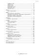
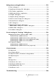

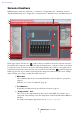


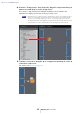
Table Of Contents
- Contents
- An overview of MRX Designer
- Screen structure
- Basic use of MRX Designer
- Menu bar
- Tool buttons
- Shortcut keys
- Design sheet
- “Parameter Sets” area
- “Parameter Link Group” area
- “Gang Edit Group” area
- “Properties” area
- Components and the component editor
- Editing the parameters
- Acoustic Echo Canceller (AEC)
- Ambient Noise Compensator (ANC)
- Audio Detector
- Auto Gain Controller (AGC)
- Combiner
- Delay
- Dynamics
- Effect
- EQ
- Fader
- Feedback Suppressor
- Filter
- Inputs/Outputs
- Meter
- Mixer
- Oscillator
- Paging
- Polarity
- Revolabs Control
- Router
- Source Selector
- Speaker Processor
- Speech Privacy
- Text
- Transmitter/Receiver
- User Defined Block
- Dialog boxes and applications
- “Print” dialog box
- “Install Speech Privacy File” dialog box
- “File Transfer” application
- “PGM1 Label Creator” application
- “Compile” dialog box
- “Snapshot Group” dialog box
- “Remote Control Setup List” dialog box
- “External Events” dialog box
- “GPI” dialog box
- “Digital Control Panel” dialog box / “Wireless DCP” dialog box / “MCP1” dialog box
- “PGM1/PGX1” dialog box
- “Port Name” dialog box
- List of settings in “Settings” dialog boxes
- Context menus
- Troubleshooting

Basic use of MRX Designer
MRX Designer User Guide
10
4. From the “Components” area at the left, drag the component that you
want to use and drop it on the design sheet.
If you drop a component that has multiple candidates such as channels, the
candidates are displayed; select the one that you want to use.
• Double-click on a component in the “Components” area to select Stamp mode; in
this mode, components are placed successively each time you click the design
sheet. To cancel Stamp mode, press <Esc> or click any component in the list.
• The input/output jacks of the MRX are not placed in the default state. Place the ports
that you want to use from “Input/Output” in the “Component” area at the left.
5. To make a connection, drag the of a component and drop it on the
of another component.
For details, refer to Connecting ports.
NOTE