
User Manual
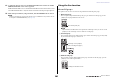
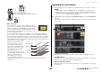
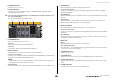
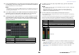
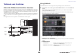
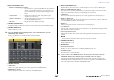
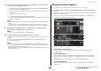
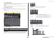
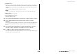
Table Of Contents
- How to Use This Reference Manual
- Contents
- Function Tree
- SELECTED CHANNEL section
- Centralogic section
- Input and output patching
- Input channels
- Signal flow for input channels
- Specifying the channel name, icon and channel color
- Making HA (Head Amp) settings
- Sending a signal from an input channel to the STEREO/MONO buses
- Sending a signal from an input channel to a MIX/ MATRIX bus
- Correcting delay between channels (Input Delay)
- Channel library operations
- Output channels
- EQ and Dynamics
- Grouping and linking
- Scene memory
- About scene memories
- Using scene memories
- Editing scene memories
- Using the Global Paste function
- Using the Focus function
- Using the Recall Safe function
- Using the Fade function
- Outputting a control signal to an external device in tandem with scene recall (GPI OUT)
- Playing back an audio file that links to a scene recall
- Using Preview mode
- Monitor and Cue functions
- Talkback and Oscillator
- Meters
- Graphic EQ, effects, and Premium Rack
- I/O device and external head amp
- MIDI
- User settings (Security)
- Recorder
- Help function
- Other functions
- About the SETUP screen
- Word clock and slot settings
- Using cascade connections
- Basic settings for MIX buses and MATRIX buses
- Switching the entire phantom power supply on/ off
- Specifying the brightness of the touch screen, LEDs, channel name displays, and lamps
- Setting the date and time of the internal clock
- Setting the network address
- Initializing the unit to factory default settings
- Adjusting the detection point of the touch screen (Calibration function)
- Adjusting the faders (Calibration function)
- Fine-tuning the input and output gain (Calibration function)
- Adjusting the channel color (Calibration function)
- Adjusting the brightness of the channel name display
- Adjusting the contrast of the channel name display
- Dante audio network settings
- Using GPI (General Purpose Interface)
- Appendices
- EQ Library List
- DYNAMICS Library List
- Dynamics Parameters
- Effect Type List
- Effects Parameters
- Premium Rack Processor Parameters
- Effects and tempo synchronization
- Parameters that can be assigned to control changes
- NRPN parameter assignments
- Mixing parameter operation applicability
- Functions that can be assigned to USER DEFINED keys
- Functions that can be assigned to USER DEFINED knobs
- Functions that can be assigned to the assignable encoders
- MIDI Data Format
- Warning/Error Messages
- Electrical characteristics
- Mixer Basic Parameters
- M IDI Implementation Chart
- Index

Talkback and Oscillator
Reference Manual
108
4. If you want to use an input jack other than the TALKBACK jack as supplementary
input for talkback, follow the steps below.
4-1. Press the INPUT TO TALKBACK patch button in the INPUT TO TALKBACK field to
open the PORT SELECT popup window.
4-2. Press the button for the input that you want to use for talkback to turn the button
indicator on.
You can select only one input at a time.
4-3. Press the CLOSE button to close the popup window.
Use the INPUT TO TALKBACK field GAIN knob and level meter to adjust the input level
of the connected mic.
NOTE
The PAD will be switched on or off internally when the HA gain is adjusted between +17 dB and
+18 dB.
Keep in mind that noise may be generated when using phantom power if there is a difference
between the Hot and Cold output impedance of an external device connected to the INPUT jack.
5. Press a button in the ASSIGN field to specify the bus(es) to which the talkback
signal will be sent (multiple selections are allowed).
NOTE
You can press the CLEAR ALL button to defeat all selections.
6. To enable talkback, press the TALKBACK ON button to turn it on.
The TALKBACK ON button will alternately turn on or off each time you press the button (Latch
operation).
While talkback is on, signals from the TALKBACK jack and the selected INPUT jack will be
output to the destination buses.
NOTE
• You can also assign talkback on/off or an ASSIGN change to a USER DEFINED key. In this case,
you can select either a Latch operation or an Unlatch operation (the function will be enabled only
while you continue holding down the key) (see page 169).
• When talkback is on, you can use the talkback dimmer to lower the monitor levels other than the
talkback signal (see page 99).
Using the Oscillator function
You can send a sine wave or pink noise from the internal oscillator to the desired bus.
1. In the Function Access Area, press the MONITOR button to access the MONITOR
screen.
In the MONITOR screen, the OSCILLATOR field lets you check the current oscillator settings,
and turn the oscillator on or off.
If you want to view or edit the oscillator settings in greater detail, use the OSCILLATOR popup
window described in step 2 and subsequent steps.
1 OSCILLATOR popup display button
Enables you to access the OSCILLATOR popup window, in which you can make detailed
oscillator settings.
2 OSCILLATOR LEVEL field
This adjusts the level of the oscillator. A meter beside the LEVEL knob indicates the output level
of the oscillator. If OSCILLATOR MODE is set to SINE WAVE, the frequency of the oscillator is
shown.
Press the LEVEL knob to adjust the oscillator level using the multifunction knob.
3 OSCILLATOR MODE field
Indicates the currently-selected oscillator mode. Pressing the MODE button repeatedly will
switch modes.
1
3
2
5
4