
User Manual
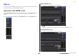
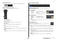
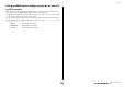
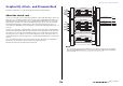
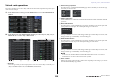
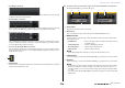
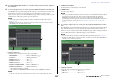
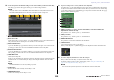
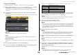
Table Of Contents
- How to Use This Reference Manual
- Contents
- Function Tree
- SELECTED CHANNEL section
- Centralogic section
- Input and output patching
- Input channels
- Signal flow for input channels
- Specifying the channel name, icon and channel color
- Making HA (Head Amp) settings
- Sending a signal from an input channel to the STEREO/MONO buses
- Sending a signal from an input channel to a MIX/ MATRIX bus
- Correcting delay between channels (Input Delay)
- Channel library operations
- Output channels
- EQ and Dynamics
- Grouping and linking
- Scene memory
- About scene memories
- Using scene memories
- Editing scene memories
- Using the Global Paste function
- Using the Focus function
- Using the Recall Safe function
- Using the Fade function
- Outputting a control signal to an external device in tandem with scene recall (GPI OUT)
- Playing back an audio file that links to a scene recall
- Using Preview mode
- Monitor and Cue functions
- Talkback and Oscillator
- Meters
- Graphic EQ, effects, and Premium Rack
- I/O device and external head amp
- MIDI
- User settings (Security)
- Recorder
- Help function
- Other functions
- About the SETUP screen
- Word clock and slot settings
- Using cascade connections
- Basic settings for MIX buses and MATRIX buses
- Switching the entire phantom power supply on/ off
- Specifying the brightness of the touch screen, LEDs, channel name displays, and lamps
- Setting the date and time of the internal clock
- Setting the network address
- Initializing the unit to factory default settings
- Adjusting the detection point of the touch screen (Calibration function)
- Adjusting the faders (Calibration function)
- Fine-tuning the input and output gain (Calibration function)
- Adjusting the channel color (Calibration function)
- Adjusting the brightness of the channel name display
- Adjusting the contrast of the channel name display
- Dante audio network settings
- Using GPI (General Purpose Interface)
- Appendices
- EQ Library List
- DYNAMICS Library List
- Dynamics Parameters
- Effect Type List
- Effects Parameters
- Premium Rack Processor Parameters
- Effects and tempo synchronization
- Parameters that can be assigned to control changes
- NRPN parameter assignments
- Mixing parameter operation applicability
- Functions that can be assigned to USER DEFINED keys
- Functions that can be assigned to USER DEFINED knobs
- Functions that can be assigned to the assignable encoders
- MIDI Data Format
- Warning/Error Messages
- Electrical characteristics
- Mixer Basic Parameters
- M IDI Implementation Chart
- Index

Meters
Reference Manual
112
INPUT/OUTPUT tabs
Use these tabs to switch between the INPUT METER screen and OUTPUT METER screen.
Fader level and meter display
This area displays the meter, fader, and level value for each channel.
1 Channel number
Indicates the channel number.
2 Σ clipping indicator
Lights to indicate that a signal is clipping at some point in the channel.
3 OVER indicator
This indicator will light if the signal clips at the METERING POINT.
4 Meter
This meter indicates the input or output level of the channel.
5 Fader
The channel level is indicated by the fader position and by a numeric value (in dB) that appears
immediately below the fader.
NOTE
Press any part of the meter area to assign the corresponding fader bank to the Centralogic
section.
Centralogic fader display
This area displays the level of the faders currently set in the Centralogic section.
METERING POINT field
Select one of the following as the metering point at which the level will be detected.
■ For INPUT METER
• PRE HPF.................... Immediately before the HPF
• PRE FADER .............. Pre-fader (immediately before INPUT
DELAY)
• POST ON................... Immediately after the [ON] key
■ For OUTPUT METER
• PRE EQ ...................... Immediately before the EQ
• PRE FADER .............. Immediately before the fader
• POST ON................... Immediately after the [ON] key
NOTE
On the CL3 or CL1 console, the metering point for output channels will also affect the optional
meter bridge (MBCL).
PEAK HOLD button
Turn on this button to hold the peak level indication on each meter. Turn off this
button to clear the peak hold indication.
2. If necessary, press a button in the METERING POINT field to switch the metering
point.
The metering point for the level meters can be set independently for input channels and output
channels.
3. If you want the peak levels of the level meter to be held, press the PEAK HOLD
button to turn it on.
PEAK HOLD button on/off operations will affect both input channels and output channels as well
as the MBCL meter bridge. When you turn this button off, the peak level indications that had
been held will be cleared.
NOTE
You can also assign the PEAK HOLD button on/off function to a USER DEFINED key
(see page 169).
1
4
5
2
3