
User Manual
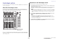
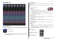
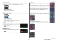
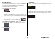
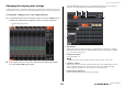
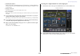
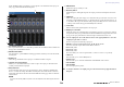
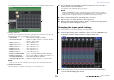
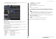
Table Of Contents
- How to Use This Reference Manual
- Contents
- Function Tree
- SELECTED CHANNEL section
- Centralogic section
- Input and output patching
- Input channels
- Signal flow for input channels
- Specifying the channel name, icon and channel color
- Making HA (Head Amp) settings
- Sending a signal from an input channel to the STEREO/MONO buses
- Sending a signal from an input channel to a MIX/ MATRIX bus
- Correcting delay between channels (Input Delay)
- Channel library operations
- Output channels
- EQ and Dynamics
- Grouping and linking
- Scene memory
- About scene memories
- Using scene memories
- Editing scene memories
- Using the Global Paste function
- Using the Focus function
- Using the Recall Safe function
- Using the Fade function
- Outputting a control signal to an external device in tandem with scene recall (GPI OUT)
- Playing back an audio file that links to a scene recall
- Using Preview mode
- Monitor and Cue functions
- Talkback and Oscillator
- Meters
- Graphic EQ, effects, and Premium Rack
- I/O device and external head amp
- MIDI
- User settings (Security)
- Recorder
- Help function
- Other functions
- About the SETUP screen
- Word clock and slot settings
- Using cascade connections
- Basic settings for MIX buses and MATRIX buses
- Switching the entire phantom power supply on/ off
- Specifying the brightness of the touch screen, LEDs, channel name displays, and lamps
- Setting the date and time of the internal clock
- Setting the network address
- Initializing the unit to factory default settings
- Adjusting the detection point of the touch screen (Calibration function)
- Adjusting the faders (Calibration function)
- Fine-tuning the input and output gain (Calibration function)
- Adjusting the channel color (Calibration function)
- Adjusting the brightness of the channel name display
- Adjusting the contrast of the channel name display
- Dante audio network settings
- Using GPI (General Purpose Interface)
- Appendices
- EQ Library List
- DYNAMICS Library List
- Dynamics Parameters
- Effect Type List
- Effects Parameters
- Premium Rack Processor Parameters
- Effects and tempo synchronization
- Parameters that can be assigned to control changes
- NRPN parameter assignments
- Mixing parameter operation applicability
- Functions that can be assigned to USER DEFINED keys
- Functions that can be assigned to USER DEFINED knobs
- Functions that can be assigned to the assignable encoders
- MIDI Data Format
- Warning/Error Messages
- Electrical characteristics
- Mixer Basic Parameters
- M IDI Implementation Chart
- Index

Centralogic section
Reference Manual
12
OVERVIEW screen
■ CHANNEL NAME field
This field appears at the top and bottom of the screen and displays the channel number, name, and icon
for the currently-selected eight channels. The name of the currently-selected channel is highlighted.
NOTE
If you have retained the channels assigned to the faders in the Centralogic section by pressing
and holding down a Bank Select key, the channel names shown at the top and bottom of the
OVERVIEW screen may differ.
■ GAIN/PATCH field
This field enables you to make HA (head amp) analog or digital gain settings and view the operational
status of the head amp.
The view and the function of the controllers in this field vary depending on the type of the selected
channel.
If the head amp is patched:
1 GAIN knob
Sets the analog gain of the head amp.
• Press this field to assign the GAIN knob to the corresponding
knob in the Centralogic section, which enables you to adjust the gain. If the Gain
Compensation function is turned on, an indicator appears, showing the level of the signal
output to the audio network.
• If the GAIN knob has been assigned to a knob in the Centralogic section, press the knob to open
the GAIN/PATCH 8ch popup window.
2 OVER indicator
Lights when the signal at the input port or from the rack output exceeds the full scale level. This
indicator is available only if an input channel is selected.
3 +48V indicator
Indicates the phantom power (+48V) on or off status for the head amp. This indicator is not
displayed unless the head amp is patched to the channel.
4 Ø (Phase) indicator
Indicates the input phase setting for the head amp. This indicator is available only if an input
channel is selected.
NOTE
• If the slot is not connected to the head amp, the patch and the type of the MY card will be
displayed.
• If GAIN KNOB FUNCTION is set to DIGITAL GAIN in the PREFERENCE screen, the digital GAIN
knob will appear instead of knob
1, and indicator 3 will not be displayed.
If the Gain Compensation function is turned on, an indicator appears, showing the level of the
signal output to the audio network.
If the slot is patched:
The slot name will appear.
If the rack is connected:
The patch and module name will appear.
If the output is connected:
Only the patch will appear.
: Selected channel
: Unselected channel
1
4
3
2