
User Manual
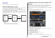
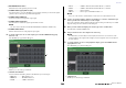
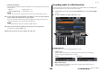
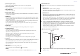
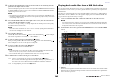
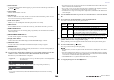
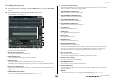
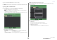
Table Of Contents
- How to Use This Reference Manual
- Contents
- Function Tree
- SELECTED CHANNEL section
- Centralogic section
- Input and output patching
- Input channels
- Signal flow for input channels
- Specifying the channel name, icon and channel color
- Making HA (Head Amp) settings
- Sending a signal from an input channel to the STEREO/MONO buses
- Sending a signal from an input channel to a MIX/ MATRIX bus
- Correcting delay between channels (Input Delay)
- Channel library operations
- Output channels
- EQ and Dynamics
- Grouping and linking
- Scene memory
- About scene memories
- Using scene memories
- Editing scene memories
- Using the Global Paste function
- Using the Focus function
- Using the Recall Safe function
- Using the Fade function
- Outputting a control signal to an external device in tandem with scene recall (GPI OUT)
- Playing back an audio file that links to a scene recall
- Using Preview mode
- Monitor and Cue functions
- Talkback and Oscillator
- Meters
- Graphic EQ, effects, and Premium Rack
- I/O device and external head amp
- MIDI
- User settings (Security)
- Recorder
- Help function
- Other functions
- About the SETUP screen
- Word clock and slot settings
- Using cascade connections
- Basic settings for MIX buses and MATRIX buses
- Switching the entire phantom power supply on/ off
- Specifying the brightness of the touch screen, LEDs, channel name displays, and lamps
- Setting the date and time of the internal clock
- Setting the network address
- Initializing the unit to factory default settings
- Adjusting the detection point of the touch screen (Calibration function)
- Adjusting the faders (Calibration function)
- Fine-tuning the input and output gain (Calibration function)
- Adjusting the channel color (Calibration function)
- Adjusting the brightness of the channel name display
- Adjusting the contrast of the channel name display
- Dante audio network settings
- Using GPI (General Purpose Interface)
- Appendices
- EQ Library List
- DYNAMICS Library List
- Dynamics Parameters
- Effect Type List
- Effects Parameters
- Premium Rack Processor Parameters
- Effects and tempo synchronization
- Parameters that can be assigned to control changes
- NRPN parameter assignments
- Mixing parameter operation applicability
- Functions that can be assigned to USER DEFINED keys
- Functions that can be assigned to USER DEFINED knobs
- Functions that can be assigned to the assignable encoders
- MIDI Data Format
- Warning/Error Messages
- Electrical characteristics
- Mixer Basic Parameters
- M IDI Implementation Chart
- Index

Recorder
Reference Manual
181
Recorder
This chapter explains the functionality and operation of the recorder.
About the USB memory recorder
The CL series console features a USB memory recorder function that lets you easily record internal
signals to a USB flash drive, or play back audio files recorded on a USB flash drive.
As the file format for recording, the CL series console supports MP3 (MPEG-1 Audio Layer-3). For
playback, it supports MP3 as well as WMA (Windows Media Audio) and AAC (MPEG-4 AAC) files.
However, DRM (Digital Rights Management) is not supported.
By using the USB memory recorder, the output from the STEREO bus or a MIX bus can be recorded to
a USB flash drive, or background music or sound effects saved on a USB flash drive can be played back
via an assigned input channel.
■ Signal flow for the USB memory recorder
* CL3: INPUT1-64, CL1: INPUT1-48
NOTE
• Recording and playback cannot be done simultaneously.
• The signal being recorded cannot be input to an INPUT channel.
Assigning channels to the input and output of the
recorder
Follow the steps below to patch the desired channels to the input and output of the USB memory
recorder. You can patch any desired output channel or the direct output of an INPUT channel to the
recorder input, and you can patch the recorder output to any desired input channel.
1. In the Function Access Area, press the RECORDER button to access the RECORDER
screen.
2. Press the USB tab in the upper right of the screen.
On this screen you can assign signals to the input and output of the USB memory recorder, and
perform recording and playback operations.
1 RECORDER INPUT popup buttons (L/R)
Press these buttons to open the CH SELECT popup window, in which you can select the signals
patched to the recorder’s L/R input channels.
2 RECORDER INPUT GAIN knob
Sets the level of the signal input to the recorder.
3 RECORDER INPUT CUE button
Press this button to audition the signal input to the recorder.
NOTE
You cannot turn on this button and the PLAYBACK OUTPUT CUE button simultaneously.
MIX1-24
MATRIX1-8
STEREO L/R
MONO
INPUT1-72*
DIRECT OUT
RECORDER
INPUT
PLAYBACK
OUT
INPUT1-72*
ST IN 1L1R-8L8R
L
R
L
R
USB memory
recorder
1 2 3 4 8765