
User Manual
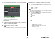
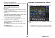
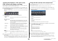
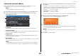
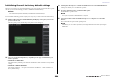
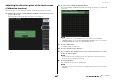
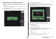
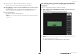
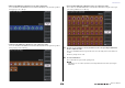
Table Of Contents
- How to Use This Reference Manual
- Contents
- Function Tree
- SELECTED CHANNEL section
- Centralogic section
- Input and output patching
- Input channels
- Signal flow for input channels
- Specifying the channel name, icon and channel color
- Making HA (Head Amp) settings
- Sending a signal from an input channel to the STEREO/MONO buses
- Sending a signal from an input channel to a MIX/ MATRIX bus
- Correcting delay between channels (Input Delay)
- Channel library operations
- Output channels
- EQ and Dynamics
- Grouping and linking
- Scene memory
- About scene memories
- Using scene memories
- Editing scene memories
- Using the Global Paste function
- Using the Focus function
- Using the Recall Safe function
- Using the Fade function
- Outputting a control signal to an external device in tandem with scene recall (GPI OUT)
- Playing back an audio file that links to a scene recall
- Using Preview mode
- Monitor and Cue functions
- Talkback and Oscillator
- Meters
- Graphic EQ, effects, and Premium Rack
- I/O device and external head amp
- MIDI
- User settings (Security)
- Recorder
- Help function
- Other functions
- About the SETUP screen
- Word clock and slot settings
- Using cascade connections
- Basic settings for MIX buses and MATRIX buses
- Switching the entire phantom power supply on/ off
- Specifying the brightness of the touch screen, LEDs, channel name displays, and lamps
- Setting the date and time of the internal clock
- Setting the network address
- Initializing the unit to factory default settings
- Adjusting the detection point of the touch screen (Calibration function)
- Adjusting the faders (Calibration function)
- Fine-tuning the input and output gain (Calibration function)
- Adjusting the channel color (Calibration function)
- Adjusting the brightness of the channel name display
- Adjusting the contrast of the channel name display
- Dante audio network settings
- Using GPI (General Purpose Interface)
- Appendices
- EQ Library List
- DYNAMICS Library List
- Dynamics Parameters
- Effect Type List
- Effects Parameters
- Premium Rack Processor Parameters
- Effects and tempo synchronization
- Parameters that can be assigned to control changes
- NRPN parameter assignments
- Mixing parameter operation applicability
- Functions that can be assigned to USER DEFINED keys
- Functions that can be assigned to USER DEFINED knobs
- Functions that can be assigned to the assignable encoders
- MIDI Data Format
- Warning/Error Messages
- Electrical characteristics
- Mixer Basic Parameters
- M IDI Implementation Chart
- Index

Other functions
Reference Manual
202
Operations on the cascade master CL unit
1. In the Function Access Area, press the SETUP button to access the SETUP screen.
2. In the SYSTEM SETUP field located in the center of the SETUP screen, press the
CASCADE button to open the CASCADE popup window.
3. Press the CASCADE IN PATCH tab to access the CASCADE IN PATCH page.
4. Press the port select popup button for the bus to which you want to assign a port.
The PORT SELECT popup window will appear.
5. Use the category select list and port select buttons to select the desired slot and
input ports, and then press the CLOSE button.
The port will be assigned to the selected bus.
6. Repeat steps 4 and 5 to assign ports to other buses.
If desired, you can assign two or more buses to the same input port.
7. If you want to link specific parameters or events between two CL series consoles,
proceed as follows.
7–1. Use the CASCADE COMM PORT field to select the port that will transmit and
receive control signals for cascade link.
The items you can select are the same as in the CASCADE OUT PATCH popup window
(see page 200).
NOTE
Control signals for the cascade link and MIDI messages cannot share the same port. If you select
a port that is already specified for transmission/reception of MIDI messages, a dialog box will ask
whether it is OK to cancel the existing settings.
7–2. Use the CASCADE LINK MODE buttons to select the item that you want to link.
The items you can select are the same as in the CASCADE OUT PATCH popup window
(see page 200).
8. To close the CASCADE popup window, press the CLOSE button.
In this state, the bus signals of the cascade slave will be sent via the slot to the buses of the cascade
master, and the combined signals of both buses will be output from the cascade master. If the
Cascade Link function is enabled, the specified operations or parameter changes performed on
either CL series console will be followed by the other CL console.
Basic settings for MIX buses and MATRIX buses
This section explains how to change the basic settings for MIX buses and MATRIX buses, such as
switching between stereo and monaural, and selecting the send point from which the signal of an input
channel will be sent.
The settings you make in the following procedure will be saved as part of the scene.
1. In the Function Access Area, press the SETUP button to access the SETUP screen.
2. In the center right of the SETUP screen, press the BUS SETUP button to open the
BUS SETUP popup window.
In the BUS SETUP popup window you can make various settings for MIX buses and MATRIX
buses.
1 SIGNAL TYPE switch buttons
Select how signals are processed for every adjacent pair of buses. Select either STEREO (stereo
signal) or MONOx2 (monaural signal x 2).
2 Bus type/send point select buttons (MIX bus only)
For every adjacent pair of buses, you can select the bus type and (for vari-type) the send point.
These buttons correspond to the following parameters.
Button Bus type Pre-fader send point
VARI [PRE EQ] VARI Immediately before the EQ
VARI [PRE FADER] VARI Immediately before the fader
FIXED FIXED ---
1 42
1 43
MIX 1–16 page MIX BUS 17–24/MATRIX BUS page