
User Manual
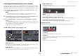
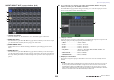
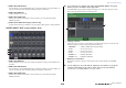
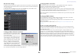
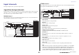
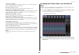
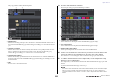
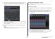
Table Of Contents
- How to Use This Reference Manual
- Contents
- Function Tree
- SELECTED CHANNEL section
- Centralogic section
- Input and output patching
- Input channels
- Signal flow for input channels
- Specifying the channel name, icon and channel color
- Making HA (Head Amp) settings
- Sending a signal from an input channel to the STEREO/MONO buses
- Sending a signal from an input channel to a MIX/ MATRIX bus
- Correcting delay between channels (Input Delay)
- Channel library operations
- Output channels
- EQ and Dynamics
- Grouping and linking
- Scene memory
- About scene memories
- Using scene memories
- Editing scene memories
- Using the Global Paste function
- Using the Focus function
- Using the Recall Safe function
- Using the Fade function
- Outputting a control signal to an external device in tandem with scene recall (GPI OUT)
- Playing back an audio file that links to a scene recall
- Using Preview mode
- Monitor and Cue functions
- Talkback and Oscillator
- Meters
- Graphic EQ, effects, and Premium Rack
- I/O device and external head amp
- MIDI
- User settings (Security)
- Recorder
- Help function
- Other functions
- About the SETUP screen
- Word clock and slot settings
- Using cascade connections
- Basic settings for MIX buses and MATRIX buses
- Switching the entire phantom power supply on/ off
- Specifying the brightness of the touch screen, LEDs, channel name displays, and lamps
- Setting the date and time of the internal clock
- Setting the network address
- Initializing the unit to factory default settings
- Adjusting the detection point of the touch screen (Calibration function)
- Adjusting the faders (Calibration function)
- Fine-tuning the input and output gain (Calibration function)
- Adjusting the channel color (Calibration function)
- Adjusting the brightness of the channel name display
- Adjusting the contrast of the channel name display
- Dante audio network settings
- Using GPI (General Purpose Interface)
- Appendices
- EQ Library List
- DYNAMICS Library List
- Dynamics Parameters
- Effect Type List
- Effects Parameters
- Premium Rack Processor Parameters
- Effects and tempo synchronization
- Parameters that can be assigned to control changes
- NRPN parameter assignments
- Mixing parameter operation applicability
- Functions that can be assigned to USER DEFINED keys
- Functions that can be assigned to USER DEFINED knobs
- Functions that can be assigned to the assignable encoders
- MIDI Data Format
- Warning/Error Messages
- Electrical characteristics
- Mixer Basic Parameters
- M IDI Implementation Chart
- Index

Input and output patching
Reference Manual
21
Inserting an external device into a channel
If desired, you can insert an effect processor or other external device into the signal path of an INPUT,
MIX, MATRIX, STEREO, or MONO channel. When doing so, the type of input/output port used for
the insertion and the location of the insert-out/in points can be specified individually for each channel.
1. As desired, connect your external equipment to an OMNI IN/OUT jack or to an
I/O card installed in slots 1–3.
NOTE
If you install a digital I/O card in a slot and digitally connect an external device, you must
synchronize the word clock of the CL console and the external device (see page 198).
2. Use the Bank Select keys in the Centralogic section to access the OVERVIEW screen
for the channel to which you want to assign the input source.
3. Press the INSERT/DIRECT OUT field to access the INSERT/DIRECT OUT popup
window.
In the INSERT/DIRECT OUT popup window, you can view or change the type of input/output
port used for insertion and the location at which insertion will occur. There are two variations of
this popup window; one-channel and eight-channel.
Each window view includes the following items.
INSERT/DIRECT OUT popup window (1ch)
1 INSERT OUT button
Press this button to open the PORT SELECT popup window, in which you can select an output
port. The name of the currently-selected port appears on the button.
2 INSERT IN button
Press this button to open the PORT SELECT popup window, in which you can select an input
port. The name of the currently-selected port appears on the button.
3 INSERT ON/OFF button
Switches the insert on or off.
To change the currently-selected insert point, press one of the three blocks that does not contain
any buttons.
NOTE
You can set the I/O ports to function as an insert for each block.
4 APPLY TO ALL INPUT button (input channels only)
Specifies whether the insert position/Direct Out position will be applied to all input channels.
5 APPLY TO ALL OUTPUT button (output channels only)
Specifies whether the insert position settings will be applied to all output channels.
■ INSERT IN HA field
This field will appear if you have selected an input port (that features a head amp) as the insert-in.
6 +48V button
Switches head amp phantom power (+48V) on or off.
7 A.GAIN knob
Indicates the analog gain setting for the head amp. Press this knob so that you will be able to use
the multifunction knob to adjust the gain.
8 HA meter
Displays the level of the HA input signal.
1
2
3
4 5
6 7 8