
User Manual
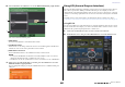
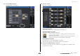
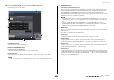
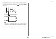
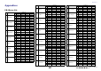
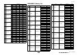
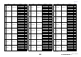
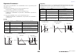
Table Of Contents
- How to Use This Reference Manual
- Contents
- Function Tree
- SELECTED CHANNEL section
- Centralogic section
- Input and output patching
- Input channels
- Signal flow for input channels
- Specifying the channel name, icon and channel color
- Making HA (Head Amp) settings
- Sending a signal from an input channel to the STEREO/MONO buses
- Sending a signal from an input channel to a MIX/ MATRIX bus
- Correcting delay between channels (Input Delay)
- Channel library operations
- Output channels
- EQ and Dynamics
- Grouping and linking
- Scene memory
- About scene memories
- Using scene memories
- Editing scene memories
- Using the Global Paste function
- Using the Focus function
- Using the Recall Safe function
- Using the Fade function
- Outputting a control signal to an external device in tandem with scene recall (GPI OUT)
- Playing back an audio file that links to a scene recall
- Using Preview mode
- Monitor and Cue functions
- Talkback and Oscillator
- Meters
- Graphic EQ, effects, and Premium Rack
- I/O device and external head amp
- MIDI
- User settings (Security)
- Recorder
- Help function
- Other functions
- About the SETUP screen
- Word clock and slot settings
- Using cascade connections
- Basic settings for MIX buses and MATRIX buses
- Switching the entire phantom power supply on/ off
- Specifying the brightness of the touch screen, LEDs, channel name displays, and lamps
- Setting the date and time of the internal clock
- Setting the network address
- Initializing the unit to factory default settings
- Adjusting the detection point of the touch screen (Calibration function)
- Adjusting the faders (Calibration function)
- Fine-tuning the input and output gain (Calibration function)
- Adjusting the channel color (Calibration function)
- Adjusting the brightness of the channel name display
- Adjusting the contrast of the channel name display
- Dante audio network settings
- Using GPI (General Purpose Interface)
- Appendices
- EQ Library List
- DYNAMICS Library List
- Dynamics Parameters
- Effect Type List
- Effects Parameters
- Premium Rack Processor Parameters
- Effects and tempo synchronization
- Parameters that can be assigned to control changes
- NRPN parameter assignments
- Mixing parameter operation applicability
- Functions that can be assigned to USER DEFINED keys
- Functions that can be assigned to USER DEFINED knobs
- Functions that can be assigned to the assignable encoders
- MIDI Data Format
- Warning/Error Messages
- Electrical characteristics
- Mixer Basic Parameters
- M IDI Implementation Chart
- Index

Appendices
Reference Manual
230
Dynamics Parameters
Input channels provide DYNAMICS section 1 and DYNAMICS section 2. Output channels provide
DYNAMICS section 1.
An input channel’s DYNAMICS section 1 provides the following four types:
GATE, DUCKING, COMPRESSOR, and EXPANDER.
An input channel’s DYNAMICS section 2 provides the following four types:
COMPRESSOR, COMPANDER-H (Compander Hard), COMPANDER-S (Compander Soft),
and DE-ESSER.
An output channel’s DYNAMICS section 1 provides the following four types:
COMPRESSOR, EXPANDER, COMPANDER-H (Compander Hard), and COMPANDER-S
(Compander Soft).
■ GATE
A gate attenuates signals below a set THRESHOLD level by a specified amount (RANGE).
■ DUCKING
Ducking is commonly used for voice-over applications in which the background music level is reduced
automatically when an announcer speaks. When the KEY IN source signal level exceeds the specified
THRESHOLD, the output level is attenuated by a specified amount (RANGE).
Parameter Range Description
THRESHOLD (dB) –72 to 0 (73 points)
This determines the level at which the gate effect is
applied.
RANGE (dB) –∞, –69 to 0 (71 points)
This determines the amount of attenuation when the
gate closes.
ATTACK (ms) 0–120 (121 points)
This determines how fast the gate opens when the
signal exceeds the threshold level.
HOLD (ms)
44.1kHz: 0.02 ms – 2.13 sec
48kHz: 0.02 ms – 1.96 sec (160 points)
This determines how long the gate stays open once
the trigger signal has fallen below the threshold.
DECAY (ms)
44.1kHz: 6 ms – 46.0 sec
48kHz: 5 ms – 42.3 sec (160 points)
This determines how fast the gate closes once the
hold time has expired. The value is expressed as the
duration required for the level to change by 6 dB.
Input Level Time Time
Output Level
Input Level
Output Level
• I/O Characteristics • Time Series Analysis
RANGE
THRESHOLD
THRESHOLD
RANGE
Input Signal Output Signal
ATTACK DECAY
HOLD
Parameter Range Description
THRESHOLD (dB) –54 to 0 (55 points)
This determines the level of trigger signal (KEY IN)
required to activate ducking.
RANGE (dB) –70 to 0 (71 points)
This determines the amount of attenuation when
ducking is activated.
ATTACK (ms) 0–120 (121 points)
This determines how soon the signal is ducked once
the ducker has been triggered.
HOLD (ms)
44.1kHz: 0.02 ms – 2.13 sec
48kHz: 0.02 ms – 1.96 sec (160 points)
This determines how long ducking remains active
once the trigger signal has fallen below the
THRESHOLD level.
DECAY (ms)
44.1kHz: 6 ms – 46.0 sec
48kHz: 5 ms – 42.3 sec (160 points)
This determines how soon the ducker returns to its
normal gain once the trigger signal level drops below
the threshold. The value is expressed as the duration
required for the level to change by 6 dB.
Input Level Time Time
Output Level
Input Level
Output Level
RANGE
THRESHOLD
THRESHOLD
RANGE
ATTACK DECAY
HOLD
• I/O Characteristics • Time Series Analysis
Input Signal Output Signal