
User Manual
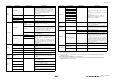
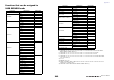
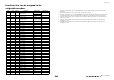
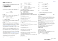
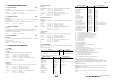
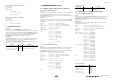
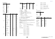
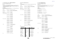
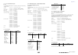
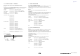
Table Of Contents
- How to Use This Reference Manual
- Contents
- Function Tree
- SELECTED CHANNEL section
- Centralogic section
- Input and output patching
- Input channels
- Signal flow for input channels
- Specifying the channel name, icon and channel color
- Making HA (Head Amp) settings
- Sending a signal from an input channel to the STEREO/MONO buses
- Sending a signal from an input channel to a MIX/ MATRIX bus
- Correcting delay between channels (Input Delay)
- Channel library operations
- Output channels
- EQ and Dynamics
- Grouping and linking
- Scene memory
- About scene memories
- Using scene memories
- Editing scene memories
- Using the Global Paste function
- Using the Focus function
- Using the Recall Safe function
- Using the Fade function
- Outputting a control signal to an external device in tandem with scene recall (GPI OUT)
- Playing back an audio file that links to a scene recall
- Using Preview mode
- Monitor and Cue functions
- Talkback and Oscillator
- Meters
- Graphic EQ, effects, and Premium Rack
- I/O device and external head amp
- MIDI
- User settings (Security)
- Recorder
- Help function
- Other functions
- About the SETUP screen
- Word clock and slot settings
- Using cascade connections
- Basic settings for MIX buses and MATRIX buses
- Switching the entire phantom power supply on/ off
- Specifying the brightness of the touch screen, LEDs, channel name displays, and lamps
- Setting the date and time of the internal clock
- Setting the network address
- Initializing the unit to factory default settings
- Adjusting the detection point of the touch screen (Calibration function)
- Adjusting the faders (Calibration function)
- Fine-tuning the input and output gain (Calibration function)
- Adjusting the channel color (Calibration function)
- Adjusting the brightness of the channel name display
- Adjusting the contrast of the channel name display
- Dante audio network settings
- Using GPI (General Purpose Interface)
- Appendices
- EQ Library List
- DYNAMICS Library List
- Dynamics Parameters
- Effect Type List
- Effects Parameters
- Premium Rack Processor Parameters
- Effects and tempo synchronization
- Parameters that can be assigned to control changes
- NRPN parameter assignments
- Mixing parameter operation applicability
- Functions that can be assigned to USER DEFINED keys
- Functions that can be assigned to USER DEFINED knobs
- Functions that can be assigned to the assignable encoders
- MIDI Data Format
- Warning/Error Messages
- Electrical characteristics
- Mixer Basic Parameters
- M IDI Implementation Chart
- Index

Appendices
Reference Manual
264
MIDI Data Format
This section explains the format of the data that the CL series is able
to understand, send, and receive.
1 CHANNEL MESSAGE
1.1 NOTE OFF (8n)
Reception
These messages are echoed to MIDI OUT if [OTHER COMMAND ECHO] is ON.
They are received if [Rx CH] matches, and used to control effects.
1.2 NOTE ON (9n)
Reception
These messages are echoed to MIDI OUT if [OTHER COMMAND ECHO] is ON.
They are received if [Rx CH] matches, and used to control effects.
1.3 CONTROL CHANGE (Bn)
Two types of CONTROL CHANGE can be transmitted and received; [NRPN] (Non-
Registered Parameter Numbers) and freely-assigned [TABLE] (1CH x 110) messages.
Select either [TABLE] or [NRPN].
Reception
These messages are echoed to MIDI OUT if [CONTROL CHANGE ECHO] is ON.
If [TABLE] is selected, these messages are received when [CONTROL CHANGE Rx] is
ON and [Rx CH] matches, and will control parameters according to the settings of the
[CONTROL CHANGE EVENT LIST]. For the parameters that can be assigned, refer
to “Parameters that can be assigned to control changes” on page 248.
If [NRPN] is selected, these messages are received when [CONTROL CHANGE Rx] is
ON and the [Rx CH] matches; the four messages NRPN control number (62h, 63h) and
DATA ENTRY control number (06h, 26h) are used to control the specified parameter.
Transmission
If [TABLE] is selected, and if [CONTROL CHANGE Tx] is ON when you operate a
parameter that is assigned in the [CONTROL CHANGE EVENT LIST], these
messages will be transmitted on the [Tx CH] channel. For the parameters that can be
assigned, refer to “Parameters that can be assigned to control changes” on page 248.
If [NRPN] is selected, and if [CONTROL CHANGE Tx] is ON when you operate a
specified parameter, the four messages NRPN control number (62h, 63h) and DATA
ENTRY control number (06h, 26h) are transmitted on the [Tx CH] channel. For the
parameters that can be assigned, refer to “Parameters that can be assigned to control
changes” on page 248.
CONTROL CHANGE messages are not used for transmission to CL Editor because
there is no guarantee that the contents of the assignment tables will match.
(PARAMETER CHANGE messages are always used.)
CONTROL CHANGE numbers 0 and 32 are for selecting banks.
If [TABLE] is selected
Equation for converting a Control Value to parameter data
paramSteps = paramMax – paramMin + 1;
add = paramWidth / paramSteps;
mod = paramWidth – add * paramSteps;
curValue = paramSteps * add + mod / 2;
(1) If the assigned parameter has fewer than 128 steps
paramWidth = 128; rxValue = Control value;
(2) If the assigned parameter has 128 or more but less than 16,384 steps
paramWidth = 16384;
(2-1) When High and Low data is received
rxValue = Control value(High) * 128 + Control value(Low);
(2-2) When only Low data is received
rxValue = (curValue & 16256) + Control value(Low);
(2-3) When only High data is received
rxValue = Control value(High) * 128 + (curValue & 127);
(3) If the assigned parameter has 16,384 or more but less than 2,097,152
steps
paramWidth = 2097152;
(3-1) When High, Middle, and Low data is received
rxValue = Control value(High) * 16384 + Control value(Middle) * 128 + Control value(Low);
(3-2) When only Low data is received
rxValue = (curValue & 2097024) + Control value(Low);
(3-3) When only Middle data is received
rxValue = (curValue & 2080895) + Control value(Middle) * 128;
(3-4) When only High data is received
rxValue = (curValue & 16383) + Control value(High) * 16384;
(3-5) When only Middle and Low data is received
rxValue = (curValue & 2080768) + Control value(Middle) * 128 + Control value(Low);
(3-6) When only High and Low data is received
rxValue = (curValue & 16256) + Control value(High) * 16384 + Control value(Low);
(3-7) When only High and Middle data is received
rxValue = (curValue & 127) + Control value(High) * 16384 + Control value(Middle) * 128;
if ( rxValue > paramWidth)
rxValue = paramWidth;
param = ( rxValue–mod / 2) / add;
If [NRPN] is selected
1.4 PROGRAM CHANGE (Cn)
Reception
If [PROGRAM CHANGE ECHO] is ON, bank select messages will also be echoed
from MIDI OUT.
If SINGLE CH is selected, these messages are received if [PROGRAM CHANGE Rx] is
ON and the [Rx CH] matches. However if [OMNI] is ON, these messages are received
regardless of the channel. When these messages are received, scene memory, effect
librarya nd premium rack library are recalled according to the settings of the
[PROGRAM CHANGE EVENT LIST].
Transmission
If [PROGRAM CHANGE Tx] is ON, these messages are transmitted according to the
[PROGRAM CHANGE Table] settings when scene memory, effect library and
premium rack library are recalled.
If SINGLE CH is selected, these messages are transmitted on the [Tx CH] channel.
If the recalled scene memory, effect library and premium rack library has been assigned
to more than one PROGRAM NUMBER, the lowest-numbered PROGRAM NUMBER
for each MIDI channel will be transmitted.
PROGRAM CHANGE messages are not used for transmission to CL Editor because
there is no guarantee that the contents of the assignment tables will match.
(PARAMETER CHANGE messages are always used.)
You can choose either MULTI MIDI CH or SINGLE CH.
If SINGLE is selected
You can choose the Rx CH, OMNI CH, and Tx CH.
You can choose whether a bank select message will be added.
A bank of up to 16 can be specified.
If MULTI is selected
The Rx and Tx channels will be the same.
The assignment table will use the settings for each MIDI channel. Bank select messages
will not be added.
You can make settings for up to sixteen MIDI channels.
STATUS 1000nnnn 8n
Note off message
DATA 0nnnnnnn nn
Note number
0vvvvvvv vv
Velocity (ignored)
STATUS 1001nnnn 9n
Note on message
DATA 0nnnnnnn nn
Note number
0vvvvvvv vv
Velocity (1-127:on, 0:off)
STATUS 1011nnnn Bn
Control change
DATA 00
Control number (00)
0vvvvvvv vv
Control Value (0-127)
STATUS 1011nnnn Bn
Control change
DATA 20
Control number (32)
0vvvvvvv vv
Control Value (0-127)
STATUS 1011nnnn Bn
Control change
DATA 0nnnnnnn nn
Control number (1-5, 7-31, 33-37, 38-95,
102-119) *
0vvvvvvv vv
Control Value (0-127)
* Numbers 0, 32, and 96–101 cannot be used.
* Control number 6, 38 can be used.
STATUS 1011nnnn Bn
Control change
DATA 01100010 62
NRPN LSB
0vvvvvvv vv
Parameter number LSB
STATUS 1011nnnn Bn
Control change *
DATA 01100011 63
NRPN MSB
0vvvvvvv vv
Parameter number MSB
STATUS 1011nnnn Bn
Control change *
DATA 00000110 06
Data entry MSB
0vvvvvvv vv
Parameter data MSB
STATUS 1011nnnn Bn
Control change *
DATA 00100110 26
Data entry LSB
0vvvvvvv vv
Parameter data LSB
* The STATUS byte of the second and subsequent messages need not
be added during transmission. Reception must occur correctly
whether or not the status byte is omitted.
STATUS 1100nnnn Cn
Program change
DATA 0nnnnnnn nn
Program number (0-127)