
User Manual
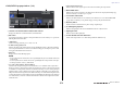
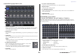
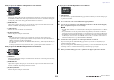
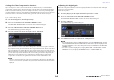
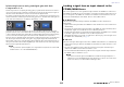
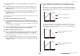
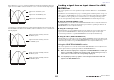
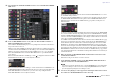
Table Of Contents
- How to Use This Reference Manual
- Contents
- Function Tree
- SELECTED CHANNEL section
- Centralogic section
- Input and output patching
- Input channels
- Signal flow for input channels
- Specifying the channel name, icon and channel color
- Making HA (Head Amp) settings
- Sending a signal from an input channel to the STEREO/MONO buses
- Sending a signal from an input channel to a MIX/ MATRIX bus
- Correcting delay between channels (Input Delay)
- Channel library operations
- Output channels
- EQ and Dynamics
- Grouping and linking
- Scene memory
- About scene memories
- Using scene memories
- Editing scene memories
- Using the Global Paste function
- Using the Focus function
- Using the Recall Safe function
- Using the Fade function
- Outputting a control signal to an external device in tandem with scene recall (GPI OUT)
- Playing back an audio file that links to a scene recall
- Using Preview mode
- Monitor and Cue functions
- Talkback and Oscillator
- Meters
- Graphic EQ, effects, and Premium Rack
- I/O device and external head amp
- MIDI
- User settings (Security)
- Recorder
- Help function
- Other functions
- About the SETUP screen
- Word clock and slot settings
- Using cascade connections
- Basic settings for MIX buses and MATRIX buses
- Switching the entire phantom power supply on/ off
- Specifying the brightness of the touch screen, LEDs, channel name displays, and lamps
- Setting the date and time of the internal clock
- Setting the network address
- Initializing the unit to factory default settings
- Adjusting the detection point of the touch screen (Calibration function)
- Adjusting the faders (Calibration function)
- Fine-tuning the input and output gain (Calibration function)
- Adjusting the channel color (Calibration function)
- Adjusting the brightness of the channel name display
- Adjusting the contrast of the channel name display
- Dante audio network settings
- Using GPI (General Purpose Interface)
- Appendices
- EQ Library List
- DYNAMICS Library List
- Dynamics Parameters
- Effect Type List
- Effects Parameters
- Premium Rack Processor Parameters
- Effects and tempo synchronization
- Parameters that can be assigned to control changes
- NRPN parameter assignments
- Mixing parameter operation applicability
- Functions that can be assigned to USER DEFINED keys
- Functions that can be assigned to USER DEFINED knobs
- Functions that can be assigned to the assignable encoders
- MIDI Data Format
- Warning/Error Messages
- Electrical characteristics
- Mixer Basic Parameters
- M IDI Implementation Chart
- Index

Input channels
Reference Manual
39
If the CSR knob is set to 100%, operating the INPUT TO ST PAN knob will change the level of
signals sent to the STEREO (L/R) bus and MONO (C) bus, as shown in the following diagram.
Operating the TO ST BALANCE knob of an ST IN channel will change the level of signals sent
from the STEREO L/R channels to the STEREO (L/R) bus and MONO (C) bus, as shown in the
following diagram.
Sending a signal from an input channel to a MIX/
MATRIX bus
This section explains how to send a signal from an input channel to MIX buses 1–24 and MATRIX
buses 1–8.
The MIX buses are used mainly for the purpose of sending signals to foldback speakers on stage, or to
effect processors. The MATRIX buses are used to produce a mix that is independent of the STEREO
bus or MIX buses, and is typically sent to a master recorder or to a backstage monitoring system.
You can send a signal from an input channel to a MIX/MATRIX bus in the following three ways.
■ Using the SELECTED CHANNEL section
With this method, you use the knobs in the SELECTED CHANNEL section to adjust the send levels to
the MIX/MATRIX buses. When using this method, signals sent from a specific input channel to all
MIX/MATRIX buses can be adjusted collectively.
■ Using the Centralogic section
With this method, you use the multifunction knobs in the Centralogic section to adjust the level of
signals sent to the MIX/MATRIX buses. When using this method, the signals sent from eight
consecutive input channels to a specific MIX/MATRIX bus can be adjusted simultaneously.
■ Using the faders (SENDS ON FADER mode)
With this method, you switch the CL series unit to SENDS ON FADER mode, and use the faders on the
top panel to adjust the level of signals sent to the MIX/MATRIX buses. When using this method, signals
sent from all input channels to a specific MIX/MATRIX bus can be adjusted simultaneously.
Using the SELECTED CHANNEL section
This section explains how to use the knobs in the SELECTED CHANNEL section to adjust the send
levels of signals sent from a specific input channel to all MIX/MATRIX buses.
1. Make sure that an output port is assigned to each MIX/MATRIX bus to which you
want to send signals, and that your monitor system, external effect processor, or
other device is connected to the corresponding output port.
2. Use the [SEL] keys on the top panel to select the input channels that will send
signals to the MIX/MATRIX buses.
CLR
PAN k n o b
Signal sent to the MONO (C) bus
Signal sent to the STEREO (L) bus
Signal sent to the STEREO (R) bus
Signal level
CLR
TO ST BALANCE knob
Signal sent from the ST IN (L) channel to
the MONO (C) bus
Signal sent from the ST IN (L) channel to
the STEREO (L) bus
Signal level
CLR
TO ST BALANCE knob
Signal sent from the ST IN (R) channel to
the MONO (C) bus
Signal sent from the ST IN (R) channel to
the STEREO (R) bus
Signal level