
User Manual
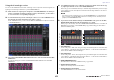

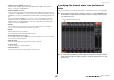
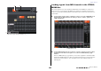
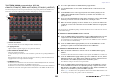
Table Of Contents
- How to Use This Reference Manual
- Contents
- Function Tree
- SELECTED CHANNEL section
- Centralogic section
- Input and output patching
- Input channels
- Signal flow for input channels
- Specifying the channel name, icon and channel color
- Making HA (Head Amp) settings
- Sending a signal from an input channel to the STEREO/MONO buses
- Sending a signal from an input channel to a MIX/ MATRIX bus
- Correcting delay between channels (Input Delay)
- Channel library operations
- Output channels
- EQ and Dynamics
- Grouping and linking
- Scene memory
- About scene memories
- Using scene memories
- Editing scene memories
- Using the Global Paste function
- Using the Focus function
- Using the Recall Safe function
- Using the Fade function
- Outputting a control signal to an external device in tandem with scene recall (GPI OUT)
- Playing back an audio file that links to a scene recall
- Using Preview mode
- Monitor and Cue functions
- Talkback and Oscillator
- Meters
- Graphic EQ, effects, and Premium Rack
- I/O device and external head amp
- MIDI
- User settings (Security)
- Recorder
- Help function
- Other functions
- About the SETUP screen
- Word clock and slot settings
- Using cascade connections
- Basic settings for MIX buses and MATRIX buses
- Switching the entire phantom power supply on/ off
- Specifying the brightness of the touch screen, LEDs, channel name displays, and lamps
- Setting the date and time of the internal clock
- Setting the network address
- Initializing the unit to factory default settings
- Adjusting the detection point of the touch screen (Calibration function)
- Adjusting the faders (Calibration function)
- Fine-tuning the input and output gain (Calibration function)
- Adjusting the channel color (Calibration function)
- Adjusting the brightness of the channel name display
- Adjusting the contrast of the channel name display
- Dante audio network settings
- Using GPI (General Purpose Interface)
- Appendices
- EQ Library List
- DYNAMICS Library List
- Dynamics Parameters
- Effect Type List
- Effects Parameters
- Premium Rack Processor Parameters
- Effects and tempo synchronization
- Parameters that can be assigned to control changes
- NRPN parameter assignments
- Mixing parameter operation applicability
- Functions that can be assigned to USER DEFINED keys
- Functions that can be assigned to USER DEFINED knobs
- Functions that can be assigned to the assignable encoders
- MIDI Data Format
- Warning/Error Messages
- Electrical characteristics
- Mixer Basic Parameters
- M IDI Implementation Chart
- Index

Output channels
Reference Manual
50
TO STEREO/MONO popup window (CH1-48,
CH49-72/ST IN(CL5), CH49-64/ST IN(CL3), ST IN(CL1), OUTPUT)
This window displays the status of signals sent from the corresponding channel to the STEREO bus/
MONO bus. You can also adjust the pan or balance setting in groups of eight selected channels.
1 Channel select button
Selects the channel. You can select multiple channels simultaneously.
2 Σ clipping indicator
Lights to indicate a signal is clipping at some point in the channel.
3 TO ST PAN/TO ST BALANCE knob
Adjusts the panning and balance.
To adjust the value, press the knob to select it, and then operate the corresponding multifunction
knob.
If the signal level reaches the overload point at any meter detection point in that channel, the Σ
clipping indicator to the right of the knob will light.
4 ST/MONO indicator
If a channel is set to ST/MONO mode, these indicators will individually indicate the on/off status
of signals sent from the channel to the STEREO bus/MONO bus.
If a channel is set to LCR mode, the LCR indicator is displayed in this location. The LCR indicator
indicates the on/off status of all signals sent from that channel to the STEREO bus/MONO bus.
3. Access the eight-channel TO STEREO/MONO popup window.
4. Use the MODE button to select either ST/MONO mode or LCR mode for each
channel.
5. In the MASTER section on the top panel, make sure that the [ON] key for the
STEREO channel/MONO channel is turned on, and then raise the fader to an
appropriate level.
6. Press one of the Output Bank Select Keys in the Centralogic section so that the MIX
channels you want to control are recalled to the Centralogic section.
7. Make sure that the [ON] keys for those channels are on, and use the fader in the
Centralogic section to raise the master level of the MIX channel to an appropriate
position.
The subsequent steps will differ depending on whether ST/MONO mode or LCR mode was selected
for the channel in step 4.
■ Channels for which ST/MONO mode is selected
8. In the TO STEREO/MONO popup window, use the STEREO/MONO button to turn
a signal sent from the MIX channel to the STEREO bus/MONO bus on or off.
For a channel that is set to ST/MONO mode, signals sent to the STEREO bus and to the MONO
bus can be switched on/off individually.
9. In the TO STEREO/MONO popup window, use the TO ST PAN knob to set the
panning of a signal sent from the MIX channel to the STEREO bus.
■ Channels for which LCR mode is selected
8. Make sure that the LCR button is turned on in the TO STEREO/MONO popup
window.
Channels for which the LCR button is off will not send a signal to the STEREO bus or MONO bus.
9. In the TO STEREO/MONO popup window, press the CSR knob to select it, and use
multifunction knobs 1–8 to adjust the level difference between signals sent from
that channel to the STEREO (L/R) bus and to the MONO (C) bus.
The CSR knob settings are the same as for input channels.
10. In the TO STEREO/MONO popup window, press the TO ST PAN knob to select it,
and use multifunction knobs 1–8 to adjust the panning of signals sent from the
MIX channel to the STEREO (L/R) bus and MONO (C) bus, and the level balance of
signals sent to the MONO (C) bus and STEREO (L/R) bus.
Refer to page 38 for details on how the signal level sent from an LCR mode MIX channel to each
bus will change according to the operation of the TO ST PAN knob.
1
2
3
4