
User Manual
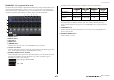
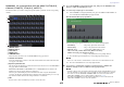

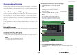
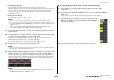
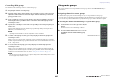

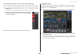

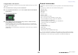
Table Of Contents
- How to Use This Reference Manual
- Contents
- Function Tree
- SELECTED CHANNEL section
- Centralogic section
- Input and output patching
- Input channels
- Signal flow for input channels
- Specifying the channel name, icon and channel color
- Making HA (Head Amp) settings
- Sending a signal from an input channel to the STEREO/MONO buses
- Sending a signal from an input channel to a MIX/ MATRIX bus
- Correcting delay between channels (Input Delay)
- Channel library operations
- Output channels
- EQ and Dynamics
- Grouping and linking
- Scene memory
- About scene memories
- Using scene memories
- Editing scene memories
- Using the Global Paste function
- Using the Focus function
- Using the Recall Safe function
- Using the Fade function
- Outputting a control signal to an external device in tandem with scene recall (GPI OUT)
- Playing back an audio file that links to a scene recall
- Using Preview mode
- Monitor and Cue functions
- Talkback and Oscillator
- Meters
- Graphic EQ, effects, and Premium Rack
- I/O device and external head amp
- MIDI
- User settings (Security)
- Recorder
- Help function
- Other functions
- About the SETUP screen
- Word clock and slot settings
- Using cascade connections
- Basic settings for MIX buses and MATRIX buses
- Switching the entire phantom power supply on/ off
- Specifying the brightness of the touch screen, LEDs, channel name displays, and lamps
- Setting the date and time of the internal clock
- Setting the network address
- Initializing the unit to factory default settings
- Adjusting the detection point of the touch screen (Calibration function)
- Adjusting the faders (Calibration function)
- Fine-tuning the input and output gain (Calibration function)
- Adjusting the channel color (Calibration function)
- Adjusting the brightness of the channel name display
- Adjusting the contrast of the channel name display
- Dante audio network settings
- Using GPI (General Purpose Interface)
- Appendices
- EQ Library List
- DYNAMICS Library List
- Dynamics Parameters
- Effect Type List
- Effects Parameters
- Premium Rack Processor Parameters
- Effects and tempo synchronization
- Parameters that can be assigned to control changes
- NRPN parameter assignments
- Mixing parameter operation applicability
- Functions that can be assigned to USER DEFINED keys
- Functions that can be assigned to USER DEFINED knobs
- Functions that can be assigned to the assignable encoders
- MIDI Data Format
- Warning/Error Messages
- Electrical characteristics
- Mixer Basic Parameters
- M IDI Implementation Chart
- Index

Grouping and linking
Reference Manual
65
3 DCA group assign field
This area displays the channels assigned to the currently-selected DCA group.
While this window is displayed, press the [SEL] key for the channel that you want to assign to the
DCA group. The on-screen fader for that channel will turn yellow and the channel will be
assigned to the DCA group. Press the same [SEL] key once again if you want to remove the
channel from the group.
4 DCA group select button
Selects the DCA group that you want to assign.
NOTE
• In the case of the CL3/CL1, faders that do not exist on those models will not be shown.
• If the [DCA 1–8] key or [DCA 9–16] key has been selected in the Centralogic section, you can
access the DCA/MUTE GROUP ASSIGN MODE popup window by pressing the [SEL] key twice
in rapid succession.
In this case, the DCA/MUTE GROUP ASSIGN MODE popup window will appear with the
corresponding DCA GROUP 1–16 button selected for that DCA group.
3. Use the DCA GROUP 1–16 buttons to select the DCA group to which you want to
assign channels.
4. Use the [SEL] keys of the input channels to select the input channels that you want
to assign to the group (multiple selections are allowed).
The [SEL] keys of the assigned channels will light, and the corresponding channels will be
highlighted in yellow in the DCA group assign field of the window.
To cancel an assignment, press a lit [SEL] key once again to make it go dark.
5. Assign channels to other DCA groups in the same way.
NOTE
You can assign a single channel to more than one DCA group. In this case, the value will be the
sum of the levels of all assigned DCA group faders.
6. When you finish making assignments, press the CLOSE button to close the popup
window, and press the × symbol in the Function Access Area (CH JOB display).
You will return to the previous screen. The DCA/MUTE GROUP field of the OVERVIEW screen
indicates the DCA group(s) to which each channel is assigned. Numbers that are lit yellow in the
upper and middle rows of this field indicate the DCA groups to which that channel belongs.
NOTE
You can also access the DCA/MUTE GROUP ASSIGN MODE popup window by pressing the
DCA/MUTE GROUP field in the OVERVIEW screen.
■ Selecting the DCA groups to which a specific channel will belong
1. Press a [SEL] key to select the input channel for which you want to make
assignments.
2. Press a knob in the SELECTED CHANNEL section to access the SELECTED CHANNEL
VIEW screen.
On this screen you can view all mix parameters for the currently-selected channel.
3. Use the DCA group select buttons to select the DCA group(s) to
which the currently-selected channel will be assigned (multiple
selections are allowed).
4. Select the DCA group(s) for other channels in the same way.